

PowerMate™
Portable
Owner's
•
&
~
I
~
·
~
· ftiEC .
Guide

PowerMate™ Portable
Owner's
Guide
LIABILITY
NEC
Information
accordance with the
Inc.
product specification. Product performance
configuration, software, the application, customer data,
control
compatible
tion
by
DISCLAIMER
Systems,
terms
of
the
system,
with the standards
customers
of
Inc.
of
the applicable
among
the product
other factors.
for
(NECIS)
which
may
vary.
products are warranted
NEC
Information
is
affected
they
While
are
NECIS
advertised,
Systems,
by
system
and
operator
products are
implementa-
in
e
~
Therefore, the suitability
determined
This
manual
however, the information
that
time.
functions, features,
oo~.
NEC
Information
NECIS
the property
approval
APC
IV
MS-DOS
PowerMate
Silentwriter
Spinwriter
by
the customer
is
as
complete
NEC
Information
or
specifications
Systems,
customers
from
is
a trademark
is
a registered trademark
is
is
and
and
employees.
of
NECIS
NECIS.
a trademark
a trademark
Pinwriter are registered trademarks
and
of
First Printing -
of
a product
and
and
in
this manual
Systems,
Inc.
shall not
NEC
Corporation.
of
NEC
of
NEC
for a specific
is
not warranted
factual
as
possible
may
Inc.
reserves the right
of
its products at
has prepared this document
The
information contained herein
be
reproduced without prior written
of
Microsoft
Corporation.
Corporation.
November
Corporation.
application
by
at the
have
been updated
of
NEC
1987
NECIS.
time
any
Corporation.
of
to
change
time,
for
must
be
printing;
since
the
without
use
by
is
e
NEC
Information
1414
Boxborough,
Printed
Copyright
Massachusetts
1987
Systems,
MA
in
U.S.A.
Inc.
Ave.
01719

FEDERAL
RADIO
This
a
Class B computing
J
of
Part
COMMUNICATIONS
FREQUENCY
unit
has
been type-tested
15
of
tection against
FCC
such
COMMISSION
INTERFERENCE
and
device
Rules,
in
accordance
which
interference
are
in
STATEMENT
found
to
with
designed
comply
the
specifications
to
provide
with the limits
reasonable
a residential installation.
for
for
Subpart
pro-
Manufacturer'S Instructions
to
Prevent Radio Frequency Interference
Manufacturer's Instructions
The
user
must
this
observe
device:
1.
Operate the equipment
turer's instructions
2.
Plug
the unit into a properly
power
3.
Always
the
following
for
cord
supplied
operate the unit with the factory-installed
unit.
4.
Make
no
modification
meeting the
5.
Maintain the equipment
6.
Use
a shielded
compliance
specified
and
of
this unit
and
User's Responsibility
precautions
in
strict accordance with the
the
model.
grounded
with the unit,
to
the equipment which
limits
of
in
a satisfactory state
properly
to
the
in
wall
unmodified.
the
Rules.
grounded
specified
installing
limits
outlet
I/O
and
cover
would
of
cable
of
the
operating
manufac-
and
use
affect
repair.
to
Rules.
the
on
the
its
ensure

User's Responsibility
The
user
is
ultimately responsible
harmful radio-frequency
this equipment
(which
is
can
encouraged
measures.
exclusively
1.
Change
2.
Change
3.
Change
4.
Change
If
these attempts are unsuccessful, install
devices:
.
1.
Line
2.
Line
3.
Electro-magnetic shielding
does
be
determined
to
try
All
of
these responsibilities
at the expense
in
in
in
in
isolation transformers
filters
emissions
cause
by
to
correct the interference
orientation
orientation
location
equipment power
for
from
interference
turning the equipment
of
the
user.
of
the
of
the equipment.
of
equipment.
correcting
problems
equipment under
to
radio
by
and any
receiving
others not mentioned are
device
source.
one
or
that arise
his
control. If _
or
television reception
off
and
on),
the
one
of
the
following
antenna.
all
of
the
following
from
user
_
If
necessary, the
user
should
radio/television technician
the
following
to
be
problems. " This
Office,
booklet
helpful:
"How
booklet
Washington,
The
be
upon
harmful
interest
ference
prepared
to
D.C.
operator
required
finding
interference
to
problem
consult the dealer,
for
additional
by
the Federal
Identify
is
available
20402,
and
from
Stock
NOTE
of a computing
to
stop
operating
that the
and
stop
operation until the inter-
has
been
NEC,
suggestions.
Communications
Resolve
the
No.
Radio-TV
U.
S.
004-000-00345-4.
device
his
device
it
is
in
is
causing
the
corrected.
or
an
experienced
The
user
Interference
Government
may
device
public
may
find
Commisson
Printing
Contents
Page
System
Setting
Connecting
Features
Your
Microdiskettes
Moving
PowerMate
Options.
Components
Up. . . . . . . . . . . . . . . . . . . . . . . . . . . . . . . . . . . . . . . . . . . . . 4
Peripheral
and
Controls
Monochrome
System
Keyboard.
First Program. . . . . . . . . . . . . . . . . . . . . . . . . . . . . . . . . . . . . .
Inserting
Write
Precautions
Display. . . . . . . . . . . . . . . . . . . . . . . . . . . . . . . . . . . . . . . . . . .
Keyboard.
Boards
Drives. . . . . . . . . . . . . . . . . . . . . . . . . . . . . . . . . . . . . . . . . . . .
Accessories. . . . . . . . . . . . . . . . . . . . . . . . . . . . . . . . . . . . . . . .
NEC
Unit. . . . . . . . . . . . . . . . . . . . . . . . . . . . . . . . . . . . . . .
Protection
Your
Computer. . . . . . . . . . . . . . . . . . . . . . . . . . . . . . . . . . .
Portable Care. . . . . . . . . . . . . . . . . . . . . . . . . . . . . . . . .
. . . . . . . . . . . . . . . . . . . . . . . . . . . . . . . . . . . . . . . . . . . . . . .
and
Printers
. . . . . . . . . . . . . . . . . . . . . . . . . . . . . . . . . . . . . 2
Options
Display
. . . . . . . . . . . . . . . . . . . . . . . . . . . . . . . . . . . . . . . . .
and
Microdiskette
and
Removing a Microdiskette.
...................................
.......................................
. . . . . . . . . . . . . . . . . . . . . . . . . . . . . . . . . . . . . . . . .
Chips
..................................
for
the
. . . . . . . . . . . . . . . . . . . . . . . . . . . .
. . . . . . . . . . . . . . . . . . . . . . . . . . . . . . . .
Care. . . . . . . . . . . . . . . . . . . . . .
. . . . . . . . . . . . . . .
PowerMate
Portable . . . . . . . . . . . . . .
11
15
16
19
21
23
24
25
26
27
29
30
30
30
31
32
33
34
If
You
Have
a Problem. . . . . . . . . . . . . . . . . . . . . . . . . . . . . . . . . . .
System
Specifications
Glossary. . . . . . . . . . . . . . . . . . . . . . . . . . . . . . . . . . . . . . . . . . . . . . .
Index
Board
Checking
. . . . . . . . . . . . . . . . . . . . . . . . . . . . . . . . . . . . . . . . . . . . . . . . .
Switch Settings ...................
Switch
..........................................
Settings
...........................
v
.........
35
.
38
.
39
47
51
55
Tables
Page
Solving
Diskette
Switch
Switch
Colors
Colors
Problems . . . . . . . . . . . . . . . . . . . . . . . . . . . . . . . . . . . . . . . . . . . .
Drive
Designation . . . . . . . . . . . . . . . . . . . . . . . . . . . . . . . . . . . .
Settings
Settings
Displayed
Displayed
for
for
When
When
AGB
AGB
as
Primary Controller
as
Secondary Controller Board. . . . . . . . . . . .
Switch
Switch
2-4
2-4
is
is
On
Off
Board .....
. . . . . . . . . . . . . . . . . . . . . . . .
. . . . . . . . . . . . . . . . . . . . . . . .
........
36
41
43
43
45
45
vi

The
NEC
APC
IVT.
PowerMate"
is
an
Portable
advanced
highperformance, transportable, personal
computer
functionality based
microprocessor.
PowerMate
adjustable
display
(LCD)
keyboard,
of
standard
Its
light weight and
make
it perfect
to
store.
continues the
quality
and
(PC).
In
addition, the
Portable
monochrome
, a
93-key
and
640
memory
for
The
PowerMate
NEC
reliability.
It
offers
on
an
80286
includes
liquid
detachable
kilobytes
.
compact
travel
and
Portable
tradition
an
cry
(KB)
size
of
full
stal
easy
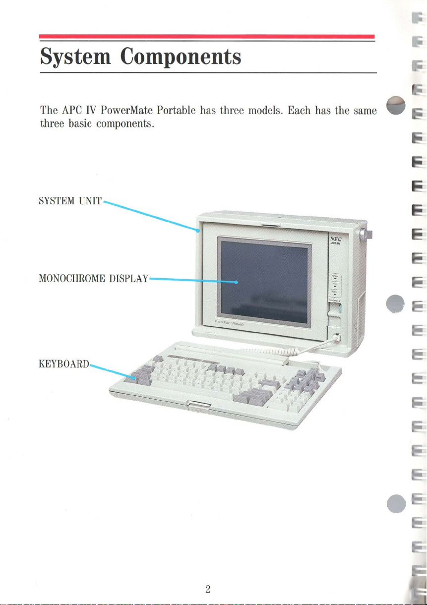
System Components
The
APC
IV
PowerMate Portable has three models. Each has the same
three basic components.
MONOCHROME
KEYBOARD
DISPLAY
---_
!--I
2
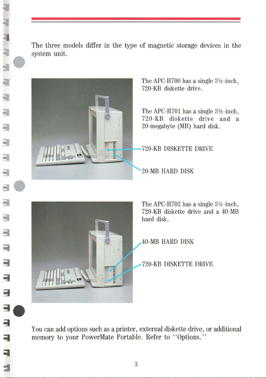
The
three
system
models
unit.
differ
in
the
type
of
magnetic storage
The
APC-H700
720-KB
The
720-KB diskette drive and a
20-megabyte
The
720-KB
hard
diskette
APC-H701
O-KB
DISKETTE
APC-H702
diskette
disk.
(MB)
devices
has a
single
drive
has a
single
hard
DRIVE
has a single
drive
.
disk.
and a
in
the
31/2-inch,
3l!z-inch,
3l!2-inch,
40-MB
You
can
memory
add
to
options
your
such
as a printer, external diskette
PowerMate
Portable.
3
-MB
720-KB
Refer
HARD
DISK
DISKETTE
to
"Options."
DRIVE
drive,
or
additional

Setting
Up
Setting
to
the
follow
If
these suggestions.
up
your
PowerMate
the
system
power
installation instructions.
you
plan
•
•
•
unit, positioning the ke
cord.
It's
to
keep
Set
up
where there
ventilation
Keep
the
surroundings, direct sunlight,
or
moisture.
Be
sure
such
as
fields.
simple
the
PowerMate
holes
PowerMate
to
keep
electric
Portable
to
do.
is
on
the
the
PowerMate
motors
consists
yboard
And
all
NEC
Portable
plenty
back
Portable
or
transformers, that
in
one
of
circulation.
of
the sys
away
excessiv
Portable
of
connecting the
and
display,
options
spot
tem
from
e dust, vibration,
away
and
come
for a while,
Avoid
unit.
excessively
from
gen
erate
keyboard
installing
with easy-to-
consider
blocking
any
the
warm
shock,
devices,
magnetic
e
e
~
4
e
E
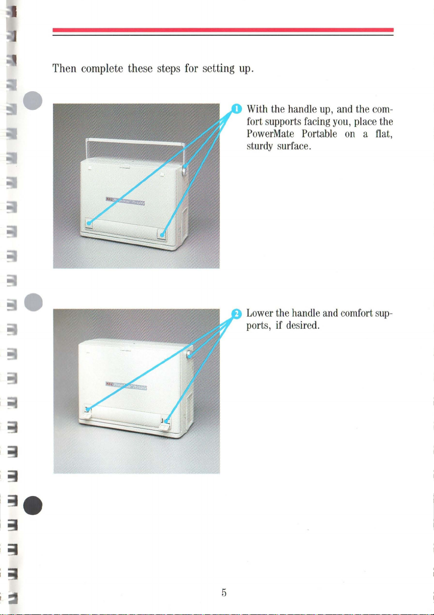
Then complete these steps for setting up.
With
fort supports
PowerMate
sturdy
Lower
ports, if desired.
the handle
facing
Portable
surface.
the handle
up,
and
and
you,
the
com-
place the
on a flat,
comfort
sup-
I
~
5
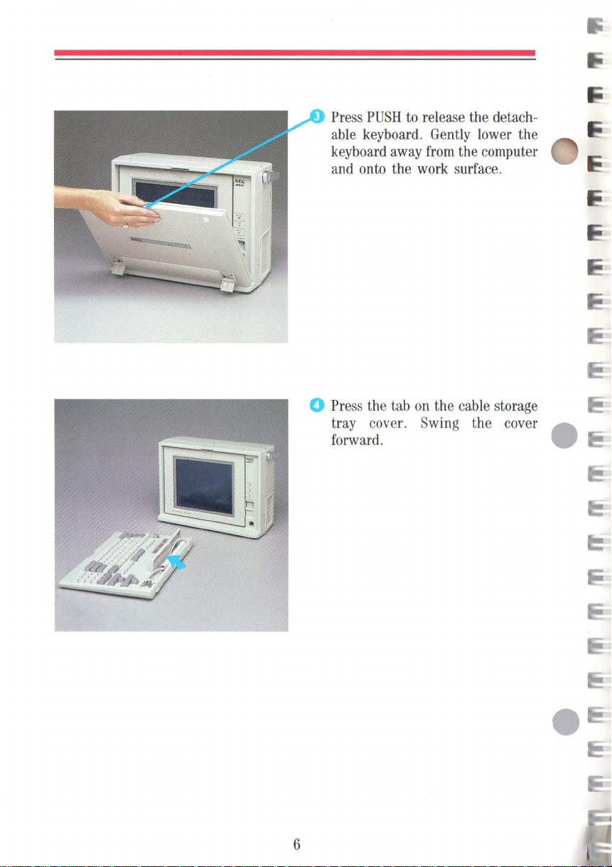
Press
PUSH
to
release the detach-
able
keyboard.
keyboard
and
onto
o
Press
the
tray cover.
forward. •
away
the
tab
work
on
Swing
Gently lower
from
the computer
surface.
the
cable
the cover A
storage
the
6

Lift
the cord out of the tray and
insert the connector, tab side up,
into the keyboard port next
display. The connector
inserted when
into position.
If
your keyboard has a protective
adhesive strip covering the status
lamps, remove it.
you
hear it
to
the
is
fully
"click"
7
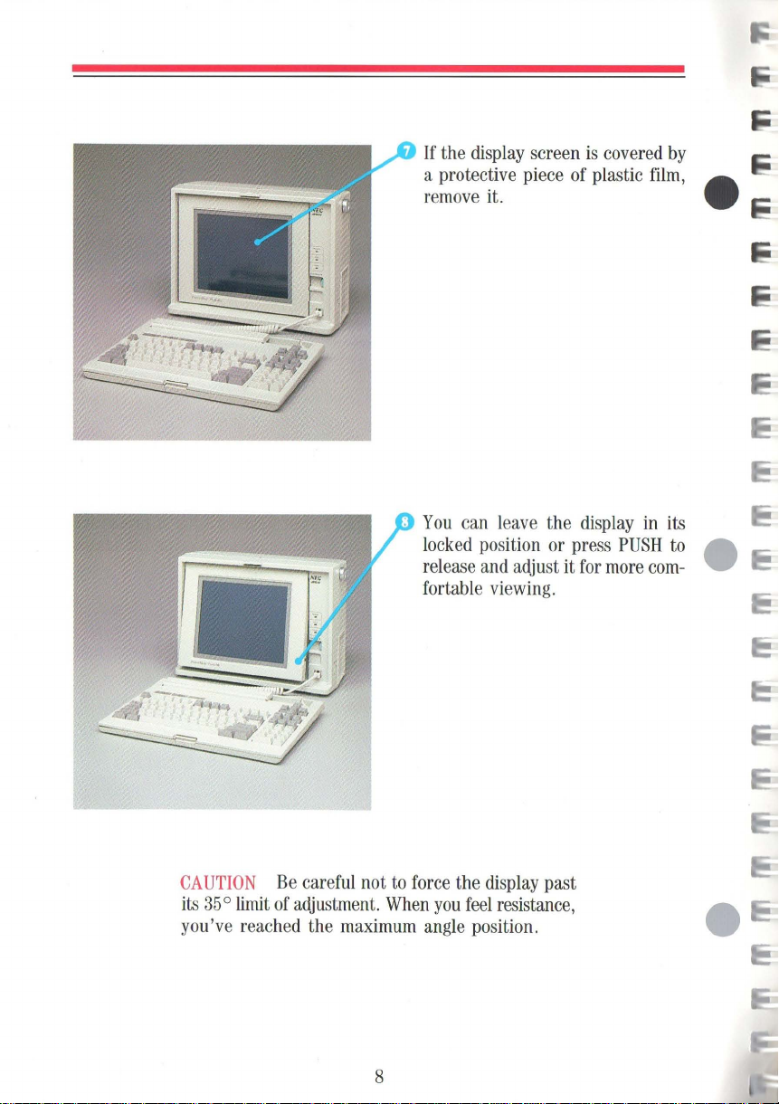
If
the
display
screen
is
covered
a protective piece of plastic
remove
You
locked
release
fortable
it. •
can
leave
the
display
position or press
and
adjust it
for
PUSH
more
viewing.
film,
in
com-
by
its
to
...
...
•
CAUTION
its
35°
limit
you've reac
Be
careful not
of
adjustment.
hed
the
to
When
maximum
8
force
you
angle
the
display
feel
position.
past
resistance,

I
.....
O_ J
--:
.p
/
---------tri\t
Check
supply
The
States
Be
in
Plug
unit.
that the
switch
correct setting
and
sure that the power switch
the 0
(off)
the
power
115/230-V
is
set correctly.
Canada
position.
cord
for
is
into
115
the
the
power
United
V .
is
system
(9
Plug
the other
cord
into a properly
outlet.
end
NOTE
approved,
safety,
do
of
the
power
grounded
The
PowerMate
three-pronged safety
not
alter the
cord.
9
Portable
cord.
comes
To
ensure
with
an
your
If
you
have
peripheral options
to
install, set
come
with the
them
section.
For
information
with the board.
up
options.
on
option
now.
Follow
board
such
as
Be
sure
the
steps
installation,
a printer,
to
read
for
modem,
the setup instructions that _
proper connection
see
the
or
diskette
in
the next •
instructions that
drive
come
After setting
up
any
desired
options,
go
to
"Your First Program."
10
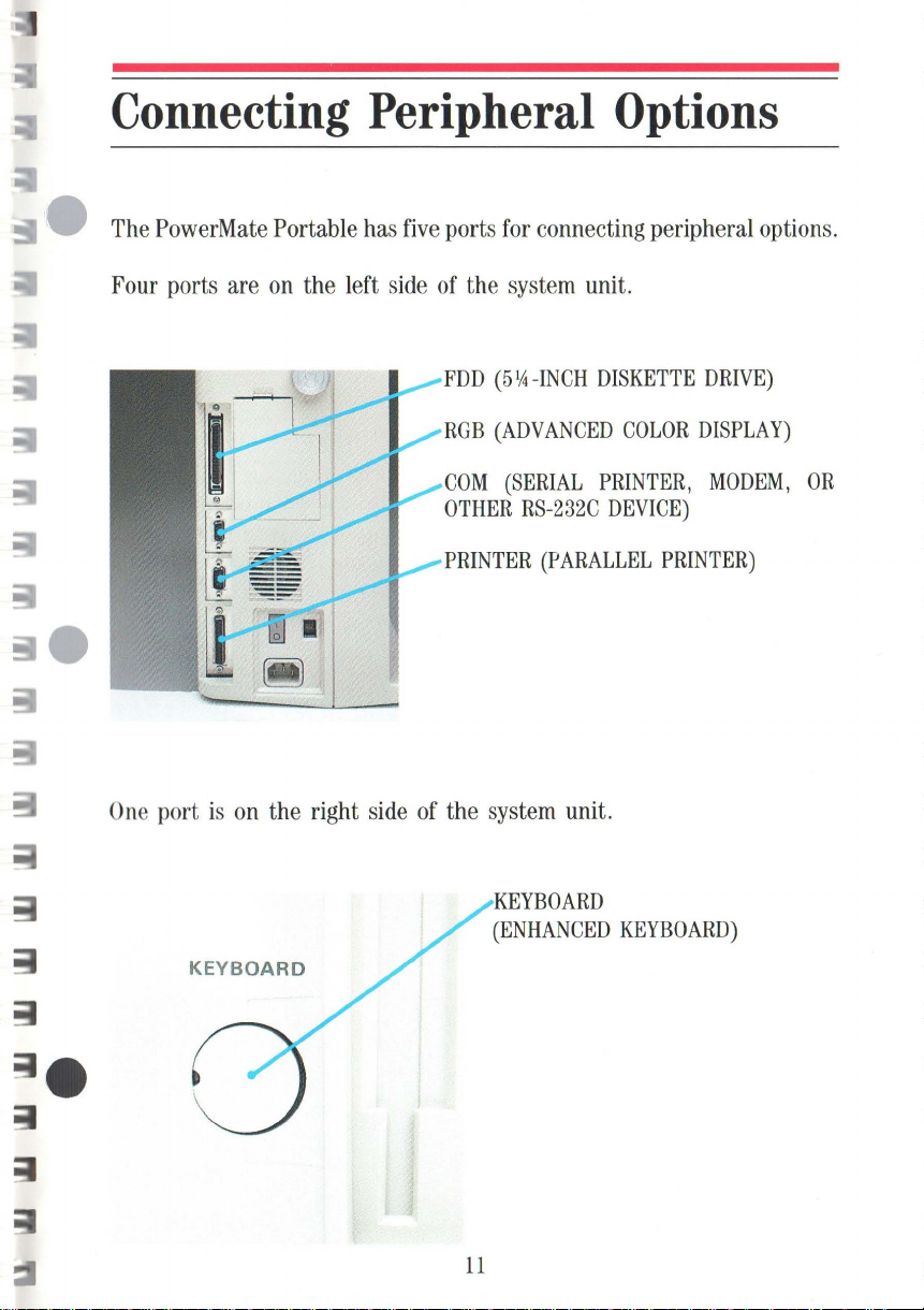
Connecting Peripheral Options
The PowerMate Portable has five ports for connecting peripheral options.
Four ports are on the left side of the system unit.
FDD
(51A
ROB
(ADVANCED
COM
(SERIAL
OTHER
-INCH
RS-232C
DISKETTE
COLOR
PRINTER,
DEVICE)
DRIVE)
DISPLAY)
MODEM,
OR
One
port
is
KEYBOARD
PRINTER
on
the right side of the system unit.
KEYBOARD
(ENHANCED
(PARALLEL
KEYBOARD)
PRINTER)
11
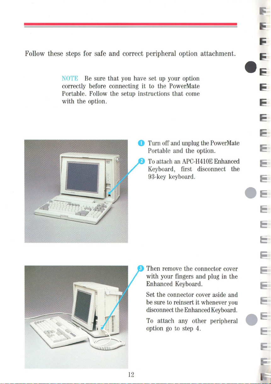
Follow these steps for safe and correct peripheral option attachment.
NOTE
correctly
Portable.
with the
Be
sure
before
Follow
option.
that
you
have
set
up
your
connecting it
the setup instructions that
to
o
Turn
Portable
To
Keyboard,
93-key
the
PowerMate
off
attach
keyboard.
and
and
an
option
come
unplug
APC-H410E
first disconnect the
the
the
PowerMate
option.
Enhanced
12
Then
remove
with
your
Enhanced
Set
the connector
be
sure
to
disconnect
To
attach
option
go
the connector
fingers
Keyboard.
reinsert it
the
to
and
cover
Enhanced
any
other peripheral
step
4.
plug
in
aside
whenever
Keyboard.
cover
the
and
you
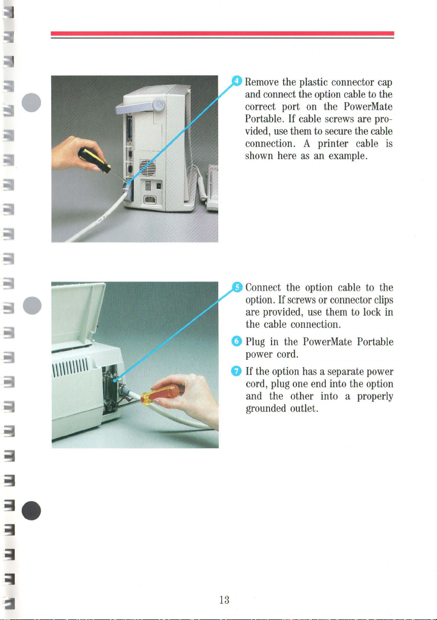
Remove the plastic connector cap
to
and connect the option cable
on
correct port
Portable.
vided, use them
connection. A printer cable
shown here as an example.
If
the PowerMate
cable screws are pro-
to
secure the cable
the
is
Connect the option cable
option. If screws or connector clips
are provided, use them
the cable connection.
to
lock in
to
the
o Plug in the PowerMate Portable
power cord.
a
If
the option has a separate power
cord, plug one end into the option
and the other into a properly
grounded outlet.
13

14

Features and Controls
MONOCHROME
The
PowerMate
POWER
Indicates power
DISK
Indicates
performing a read
operation.
DISPLAY
Portable features a high-resolution,
LAMP
BUSY
LAMP
when
(Green)
on.
(Red)
the hard
or
write
disk
is
blue
backlit,
display.
NOTE
changed
speed,
press the -(minus)
Clock
The 8-or
by
keyboard input.
hold
down
speed
is
also
lO-MHz
Indicates when the
operating at
CONTRAST
Turn
brightness .
lO-MHz
the
key
software selectable.
Ctrl
on
LAMP
to
adjust the
clock
speed
To
switch the
and
Alt
keys
the numeric
10
MHz.
DIAL
display
can
and
system
be
clock
keypad.
is
.....;.
______
DISPLAY
Push
positioning.
KEYBOARD
Connector
keyboard.
15
RELEASE
to
unlock
the
display
CONNECTOR
for
the
93-key
for

SYSTEM
UNIT
o
r1
~
j~
SWITCH
See
Settings. "
DISKETTE
Press
the
DISKETTE
31h-inCh
DISKETTE
Indicates when a
reading
HARD
20-MB
APC-H701
in
RESET
Insert the point
press
erasing
system
COVER
"System
RELEASE
to
release a diskette
drive.
DRIVE
720-KB
DRIVE
or
writing
DISK
DRIVE
hard disk
or 40-
model
APC-H702.
BUTTON
to
perform
any
programs
memory
Board
diskette
driv
in
MB
of a pen
a "cold
.
Switch
BUSY
to a di
model
hard
BUTTON
from
drive.
LAMP
e is
skette.
disk
and
boot,"
in
the
KEYBOARD
Connector
enhanced
16
CONNECTOR
for
an optional
lOl-key
keyboard.

OPTION
Remove
optional
Modem
option
FDD
drive
RGB
display
COM
SLOT
this
APC-H750
Board
slot
(optional 51,4-inch
connector)
(optional
connector)
(optional
connector)
COVER
cover
is
3.
advanced
RS-232C
when
Internal
installed
an
in
diskette
color
PRINTER
(optional parallel
printer connector)
POWER
Press 1 to
Press 0 to
115/230
Selectable
SWITCH
turn
on
turn
off
V
POWER
115-V
supply.
ACINPUT
power.
power.
SUPPLY
or
230-V
~_---
SWITCH
power
I
17

TOP
OPTION
Covers
option
Slots 1 and
up
to
two
51
2-KB
Memory
option
boards.
cated slot
H750
Internal
Remove
this
installation.
ABLE
Use
this handle
PowerMate
place
to
another.
down
easily
storage.
SLOT
COVER
slots
1,
2 are available
optional
APC-H450
Boards
Slot 3 is a dedi-
for
the optional
Modem
cover
for
HANDLE
to
carry the
Portable
for
from
It
swings
compact
2,
and
or
other
APC-
Board.
board
one
PC
for
3.
_
.,
18

KEYBOARD
The
PowerMate
1 applications
is
described
Portable features a detachable,
program.
For
specific
information,
below.
93-key
see
the
keyboard.
guide
that
Often
comes
keyboard
with
your
usage
depends
software.
upon
General
your
software
keyboard
usage
NOTE
When
repeats itself until
Most
of
the
you
hold
down a key,
CABLE
P"tects
the
SLIDE
(under
Face the keyboard
switch
the original
Caps
STATUS
Indicate the status
Lock, Num
Scroll
STORAGE
the keyboard cable when ,... - -
PC
is
in
transit. _
SWITCH
cable
storage tray
to
the right
position
Lock
keys.
LAMPS
(Numeric)
Lock
keys.
keys
you
rel
TRAY
and
when
of
of
the
Lock,
hav
e a repeat function.
the character
ease
the
key
~__..,
cover)
slide
this
you
swap
the
Ctrl
and
Caps
(Capital)
and
the
or
function
.
.....
Use
these
keys
for
controlling the
- _' :
______
r.--::--=--=-~~~-::--::-
Use
...-;;;;0i0I
these
keys
like
___
~
~~~~
typewriter
keys.
~L""'L
~"!I
4 5 •
\
~ \ ~
direction
also
operative
NUMERIC
Use
numeric
the Shift
To
the cursor, press the
Lock
To
Num
of
the cursor.
function
these
use
lamp
return
Lock
when
(Num
KEYPAD/CURSOR
keys
keypad
keys
these
keys
goes
to
numeri
key.
These
the
keypad
Lock
lamp
like a numeric
mode
(Num
work
in
reverse.
to
control the direction
Num Lock
off).
c k
eypad mode,
keys
is
is
lit).
CON
keypad. In
Lock
key
TROL
lamp
(Num
press
KEYS
the
on),
of
the
CTRL
and
CAPS
LOCK
Key
caps
are interchangeable
software application
NOTE
Ctrl
the
to
When
and
Caps
slide
switch, located
the right.
you
Lock
program
swap
the original
keys,
face the key board
inside
for
specific
needs.
the
position
cable
Use
these
particular software.
of
the
and
mov
storage tray,
keys
for
functions
e
specific
to
your
COMFORT SUPPORTS
Open
these
the
angle
of
your
needs
.
inged
supports
the keyboard
to
to
adjust
suit
.e:::,
.AJ
~
.,
~
. :~
~======
r'
~
..,
~
o
....
19

20

Your
First
Program
After setting
for use. The
necessary software to boot-up and ready the system. Follow these steps
to get starte
up
the PowerMate Portable, you must prepare the system
MS-DOSTM
d.
System Diskette
that
Turn
on
The
POWER
lamp
light.
The
power
Adjust
the
desired
Insert
ette,
label
diskette
Be
sure
the
drive
button
is
fully
is
supplied contains the
power.
lamp
and
the
on
screen appears.
the contrast
screen brightness.
the
MS-DOS
side
drive.
to
insert the diskette into
fully.
pops
inserted.
out
dial
facing
The
diskette
when
System
left,
the diskette
10-MHz
to
achieve
into
release
Disk-
the
Press
F1
to
load
the
memory. The
of
front
The
drive
while
the
loading
One
or
two
program
The program's Entry menu
appears, indicating
of
the
booting
busy
the
drive
will
makes a clicking
program loads.
takes about
beeps
indicate that
is
loaded.
routine.
21
program
lamp
light.
10
the
completion
into
on
the
sound
Program
seconds.
the

If
anything does not work as described, see
boot-up,
how to run the program. _
go
to your
MS-DOS
jor
the APe
"If
You
Have a Problem." After
IV
Series Guide for instructions
on
...
When
steps
you
to
are
shut
NOTE
must
System
finished
down
Whenever
run
the
Diskette.
running the
the
you
install
System
Setup
System
PowerMate
or
remove
program
on
Setup
an
option,
the
MS-DOS
program,
you
complete
Portable.
Press the diskette release button to
eject the diskette from the drive.
e Turn power off.
these
CAUTION
diskette
remove
from
the diskette
To
the
avoid
drive
diskette
when
before
22
damage,
the
turning power
busy
never
lamp
is
off.
remove
on.
Always
a

Microdiskettes
The
PowerMate
Each
microdiskette
face
is
protected
the diskette
read/write area
Each
double-sided
360
pages
store information.
is
of
Portable
is
from
fingerprints
ejected
of
the diskette.
microdiskette stores
text.
You
Refer
and
uses
housed
from
the drive, the shutter
must
to
the
formatting instructions.
Microdiskette
NEC
31f2-inch
in
a hard plastic jacket.
and
format blank diskettes
MS-DOS
dust
up
for
by
to
double-sided
an
automatic shutter.
slides
720
KB,
the
APe IV Series
microdiskettes.
The
diskette
over
the
equivalent
to
prepare
Guide
Care
sur-
When
exposed
to
about
them
to
for
Front
of
Microdiskette
AUTOMATIC
WRITE
SHUTTER
JACKET
PROTECT
SLIDER
TAB
'"-_--
,--_-
--~
_~'
AUTOMATIC
LABEL
.....,.,
-----~~~
Back
of
Microdiskette
SHUTTER
!lII
23

INSERTING
To
correctly insert and remove a microdiskette, follow these guidelines. e
AND
REMOVING A MICRODISKETTE
Hold
it, label
drive.
Be
into the drive
release button
micro
Never
turning
software instructions
Press
remove
the microdiskette
side
facing left, into the
sure
to
insert the microdiskette
fully. The
pops
diskette
insert a microdiskette
the diskette
is
fully
on
power,
release
the diskette.
and
insert
diskette
out when the
inserted.
before
even
if
your
say
to
do
so.
button
to
24
Always
before turning power
Never
button when the
remove a micro
press the diskette release
busy
diskette
off.
lamp
is
on.

WRITE
You
PROTECTION
can
write protect
your
micro
accidentally overwrite information.
diskette
to
ensure that
you
do
not
When
on
it until
a diskette
you
is
write protected,
remove
the write protection.
you
cannot store (write) information
To
write protect a
diskette,
uncover
Write
slide
the square
Protected
31fz-inch
the write protect
hole.
micro-
tab
to
25
Write
Enabled
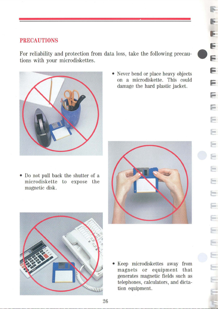
PRECAUTIONS
For reliability and protection from data loss, take the following precau- e
tions with your microdiskettes.
• Never bend or place heavy objects
on a microdiskette. This could
damage the hard plastic jacket.
•
Do
not pull back the shutter of a
diskette
micro
magnetic disk.
to expose
the
• Keep micro diskettes away from
magnets
generates magnetic fields such as
telephones, calculators, and dictation equipment.
or
equipment
26
that

Moving
Light
tabl
fr
om
e. Foll
weight a
one location
nd compact
ow these
Your
size
simple
to
steps when preparing
another.
Computer
make
it
easy
to
move
to
o
Be
sure
to
turning power
turned
memory
Each
own
'
'"''''4!~
Press the diskette release button
eject the microdiskette.
off,
(RAM)
application program has its
instructions
your
PowerMate
move
your
computer
save
your
files
off.
When
data in random
is
lost.
for
saving
Por-
before
power
access
files.
is
to
o At the
RETRACT
retract the heads of the hard
o Turn power
o
Unplug
outlet and
Store the power
pl
ace.
A>
prompt, key-in
and press
off.
the power cord
from
the unit.
cord
ENTER
disk.
from
the
in
a safe
to
o Disconnect and store any
peripheral options.
Disconnect the keyboard
in
the cable
Push in the
position.
the cable storage tray.
display
and
to lock
store
it
in
27

Lift the keyboard and fold the
comfort supports inward. Lower
the tabs into the holes in front of
the display.
I Press the bottom of the keyboard
to lock it in position.
e
~
~
_-";:..:1'
28
Lift the handle and
go!

PowerMate Portable Care
For
safety
always
Mate
Portable
Periodically clean the outside
unit with a
born
stains with a cloth
dampened
Never
use
on
any
Portable.
before
soft
cloth.
with a
strong cleaners
part
of
unplug
Remove
mild
the
the
Power-
cleaning it.
of
the
stub-
slightly
detergent.
or
solvents
PowerMate
29

Options
The following paragraphs describe
NEC
options for the PowerMate Por-
table. Installation instructions come with each option.
DISPLAY
Advanced Color Display
APC-H431
The
Advanced
Color
Display
Advanced
cally
adjusts
cies
from
compatibility with many color
graphics boards.
This
high-resolution
used
with the
well
as
H444
Advanced
the
APC-H440
or the
APC-H441
Board.
Color
to
15.75
PowerMate
systems
display
KHz
containing the
Graphics
Color
KEYBOARD
Display
board
to
35
display
Portable
Board
Graphics
Advanced
automati-
frequen-
KHz
for
can
be
as
APC-
Plus,
Board,
Graphics
Enhanced
Keyboard
Enhanced Keyboard
APC-H410E
This
industry-standard, enhanced
10
I-key keyboard
the
PowerMate
models
sonal
386.
30
in
the
computers, and the
is
compatible with
Portable,
APC
IV
all
series
of
PowerMate
other
per-

BOARDS
AND
CHIPS
512-KB 16-Bit Memory Expansion
Board
APC-H450
~
~e
:!J
512-KB
Expansion
Internal
16-Bit
Board
Modem
Memory
Board
Increases the
512
KB
and
for
installing
Memory
has
a total
Up
to
two
installed
512-KB Memory Expansion Kit
APC-H451
This
IS-chip kit
APC-H450
80287 Math Coprocessor
APC-H552
Adds
an
thus increasing the
table's
crunching"
plex
Internal
APC-H750
This
full-duplex transmission at
bits per
slot
processing
scientific
intelligent
second
in
the
system
has
sockets
up
to
Expansion
memory
memory
in
the
PowerMate
adds
Memory
additional microprocessor,
applications
and
Modem Board
modem
(bps)
PowerMate
memory
on
the
three
APC-H451
Kits.
The
capacity
Expansion
PowerMate
speed
mathematical
of 2 MB.
boards can
Portable.
512
KB
for'
'number
such
as
board
permits
300/1200
via a dedicated
Portable.
board
board
to
Board.
Por-
com-
tasks.
by
be
the
31

DRIVES
5%-inch 1.2-MB External Diskette
Drive
APC-H723
a 5
1
A
-inch
drive
1.2-MB
to
the
external
PowerMate
Adds
diskette
Portable.
5%-inch 360-KB External Diskette
Drive
APC-H724
a 5
1
A -inch
drive
360-KB
to
the
external
PowerMate
Adds
diskette
Portable.
3%-inch 720-KB Diskette Drive Kit
APC-H720
Adds a second
nal
diskette
31/2-inch
drive
to
720-KB
the
PowerMate
inter-
Portable.
3%-inch 20-MB Hard Disk Kit
APC-H721
Adds a 31fz-inch
to
the
PowerMate
20-MB
Portable.
hard
disk
drive
3%-inch 40-MB Hard Disk Kit
APC-H722
Adds a 31f2-inch
to
the
PowerMate
40-MB
Portable.
hard
32
disk
drive

ACCESSORIES
Carrying
Case
APC-H760
This carrying case is designed
specifically for transporting the
PowerMate Portable comfortably.
Printer
Cable
APC-H490
RS-232C
Cable
APC-H491
Printer Cable
33

NEC
PRINTERS
NEC
makes
table.
These
Pinwriter™
printers.
FOR
several
printers that are
include the
multimode
THE
POWERMATE
following
dot
matrix printers,
PORTABLE
compatible
Spinwriter®
and
with
your
PowerMate
letter-quality printers,
SilentwriterTM
LC-800
IEJ· •••
Por-
page
e
I::
I::
Silentwriter
8850
Spinwriter
Pinwriter
P7
LC-800
3550
Spin
Pin
writer
Pinwriter
writer
P6
P9XL
34

If
You
The PowerMate Portable has a built-in checking program that automatically
tests its components when you turn
the system, intermittent beeping occurs.
you turn on power, turn power off and call your
If
you
encounter a problem with the PowerMate Portable and beeping
not occur, the problem
First check the items in the following checklist.
[.13'
[.13'
[.13'
[.13'
[.13'
Have a Problem
on
power.
If
is
usually a simple one
The power switch
All
cables and power cords are tightly connected.
The power cord is plugged into a working outlet. Test the outlet
by
plugging in a lamp or other electrical device.
The
115
/230-V power supply switch is set correctly.
The display contrast dial is adjusted properly.
is
on.
If
there
is
a problem in
this happens repeatedly when
NEC
dealer.
does
that
you
can solve yourself.
[.13'
If
these items
If
you still
dealer.
Any option
Mate Portable and is set
do
can't
that
you have installed
not help, see the following "Solving Problems" table.
determine the problem, call your PowerMate Portable
up
35
is
correctly.
designed for the Power-

SOLVING
PROBLEMS
Problems and Symptoms
A diskette
•
POWER
• Diskette drive busy lamp doesn't
come on when you insert the
diskette.
• Power-on screen appears
display.
won't
lamp
is
load.
on.
on
the
The screen stays dark.
•
POWER
•
All
• The display contrast dial
correctly.
lamp
is
on.
cable connections are tight.
is
adjusted
The display's power-on self-test
on
remains
the screen.
Corrective Actions
Check
that
the diskette
correctly.
If
so, try a different diskette. If this
loads, the problem
Call your software dealer.
If this won't load, call your PowerMate
Portable dealer.
Call your hardware dealer.
Press
Fl.
If
displayed, load a different diskette.
Press
Fl.
have a software problem. Call your
software dealer.
If the power-on screen
displayed, call your PowerMate
Portable dealer.
is
the power-on screen
If
the diskette loads, you
is
inserted
in
your software.
is
is
still
still
A distorted image appears
display screen.
on
the
Adjust the display contrast dial.
doesn't help , turn the unit off for a
few seconds and then turn it back on.
If the problem persists, call your hardware dealer.
36
If
that

SOLVING
PROBLEMS
(CONT'D)
Problems and Symptoms
Keyboard
seems'
Graphics characters or
'dead."
"garbage"
appear on the screen when
the keyboard.
Constant screen movement.
you
use
Corrective Actions
Be sure
is tight.
If
dealer.
Run a different program. If this runs
properly, you have a software problem.
Portable
Magnetic field
display.
close by, or other device with a motor
generating a magnetic field (for example, a fan), move the display or device
away from the affected display.
that
the keyboard connection
so, call your PowerMate Portable
If
it doesn't, call your PowerMate
dealer.
is
affecting your
If
you have another display
37

System Board Switch Settings
These
are the
for
the
PowerMate
ches
are located under the switch
cover
on
unit.
SW4
factory
Portable.
the outside
switch settings e
of
the
The
system
~
I;
swit-
38
EGA
eGA
SW3
SW2
SWI

CHECKING
The
following
If
you
need
SWITCH
pages
to
change
these guidelines.
SETTINGS
describe
any
the switch setting functions.
settings
for
your
particular application,
follow
WARNING
ing
any
•
To
change the
•
Use
a pointed instrument
any
of
the other settings.
is
ting
to
Always
switch setting.
toggle
the left.
turn power
switch setting,
such
as
The
ON
off
simply
the
tip
setting
before chang-
flip
the switch
of a ballpoint
is
to
the right.
pen
The
up
or
to
change
OFF
down.
set-
39

40

Switch 4
DISPLAY
SW4-8
ON:
Color
OFF:
Monochrome
TYPE
display
display
•
•
:.1
:.
1
•
•
SW4-1
On
Off
On
Off
DISKETTE
SW4-2
On
On
Off
Off
SW4-8
SW4-7
SW4-6
SW4-5
SW4-4
SW4-3
SW4-2
SW4-1
TOGGLE
DRIVE
__
--
SWITCH
DESIGNATION
Diskette Drive Designation
Drive
A - First internal
Drive
B -
Second
Driv
e B - First internal
Drive
A -
Second
Drive
A - First internal
Drive
B - External
Drive
B - First internal
Drive
A - External
internal
internal
1
(5
,<\
-inch)
1
(5
,<\
-inch)
,J
'M
DISKETTE
SW4-7
ON:
OFF:
DISKETTE
SW4-6
ON:
OFF:
SERIAL
SW4-5
ON:
OFF:
SERIAL
SW4
ON:
OFF:
PARALLEL
SW4-3
ON:
OFF: Disables
TOGGLE
DISPLAY
NOTE
when
the built-in
(AGB).
PowerMate
UP:
DOWN:
DRIVE
Second
First
(3FO
DRIVE
Enables
Disables
PORT
Enables
Disables
PORT
-4
Enables
Disables
PORT
Enables
SWITCH -OPTIONAL
TYPE
This
an
optional
The
setting
Portable
APC
Display
similar enhanced
Other
display
CONTROLLER
(370
hex -377
hex -3F7
CONTROLLER
diskette
diskette
CHANNEL 2 (COM)
serial port channel 2
serial port channel 2
CHANNEL 1 (COM)
serial port channel 1
serial port
parallel port
parallel port
SELECT
switch setting
display
Advanced
has
display.
IV
Advanced
(APC-H431)
color
or
41
hex)
hex)
drive
controller
drive
controller
channell
only
is
connected
Graphics
no
effect
Color
or
color
monochrome
I/O
valid
valid
applies
to
Board
on
the
other
display
ADDRESS

42

Switch
3
SWITCH
SETTINGS
FOR
AGB
AS
SECONDARY
DISPLAY
CONTROLLER
BOARD
SWITCH
SW3-1
On
Off
On On
Off
On
Off
SETTINGS
FOR
AGB
AS
PRIMARY
Switches
SW3-2 SW3-3 SW3-4
Off Off
Off
On
Off
Off
Off
On
On
On
On
On
On
Off
Off
Off
Off
SW3-4
SW3-3
SW3-2
SW3-1
DISPLAY
Advanced Color/
Graphics Monochrome Graphics
Board Board Board
Color
Display
40x25
Color
Display
80
x 25
Enhanced
Display
Emulation
Mode
Enhanced
Display
High
Resolution
Mode
Monochrome
Monochrome
CONTROLLER
Configuration
Secondary
Se
condary
Secondary
Secondary
BOARD
-
-
-
-
Se
condary
40x25
Se
condary
80x25
Switches
SW3-1
On
Off
On
Off
On
Off
Nom
of
the built-in
color/graphics
board
c
These
will
SW3-2
On
On
Off
Off
On
On
switch
board
function
install a second
AGB.
AGB
SW3-3
On
On
On
On
Off
Off
settings
If
an
is
also
as
described
in the
Advanced Color/
Graphics Monochrome Graphics
SW3-4
On
On
On
On
On
On
NOTE
of
the built-in
controller board.
monochrome
install a
determine
optional
Board Board Board
Color
Display
40x25
Color
Display
80
x 25
Enhanced
Display
Emulation
Mode
Enhanced
Display
High
Resolution
Mode
Monochrome
Monochrome
These
switch
AGB
when it
The
or
color/graphics board.
second
the
AGB
function
monochrome
installed, the secondary
here.
You
cannot
PowerMate
Portable.
Configuration
Primary
Primary
Primary
Primary
-
-
settings
determine
is
acting
primary
in
the
PowerMate
or
-
-
-
-
Primary
40x25
Primary
80x25
the
as a secondary
board
must
You
Portable.
function
be
cannot
a
~
I
43

Switch 2
The
PowerMate
and
white.
It
does
to
be
used
with software that
detennine
on
The
to
display. All
most
To
indicate
the
For
on a blue
ON.
If
you
colors
the
which
the
LCD.
factory
select a
background
example,
These
background
settings
colors
software applications.
background
that
your
if
background,
settings indicate that white
forget
to
will
not
Portable
not
display
colors
for
display
color
color
you
have
set
your
be
visible
.
has
a liquid crystal
colors
or
shades
does
display
will
or
will
not
be
"translated"
switches
color
choice
and
the other
a software application that
set
background
on
2-1
on a black
other than
is
not
foreground color(s)
switch
the
2-1
LCD.
through
background.
black,
displayed.
to
OFF
is
color
to
They
display
of
gray.
colors.
2-4
allow
set switches
This will
and
displayed
"not
displayed
will
appear
(LCD)
However,
Switches
for
black
all
colors,
These
settings
create
that
you
displays
switches
and
blue
to
be
that
displays
the
LCD
is
designed
2-1
through
and
white
except
accommodate
2-1
through
a contrast
select
white characters
2-2
is
," other
the
for
through
not
displayed.
foreground
same
between
display.
color
black
2-4
display
black,
2-4
to
2-4
to
as
e
44

Switch 2
SW2-8
SW2-7
SW2-6
SW2-5
S
W2-4
SW2-3
SW2-2
SW2-1
400-LINE
(EGA
SVV2-8
ON:
OFF:
EMULATION
(EGA
SVV2-7
ON:
OFF:
'FOR CON
~
MONITOR
PLUS
FUNCTIONS)
200
lin
e (normal)
400
line
mode
ENABLE/DISABLE
PLUS FUNC
Disable
Enable
CO
LOR
GRAPHICS
DISPLAY
NORMAL/REVERSE
SVV2-6
ON:
Selects
(bl
OFF
: Selects reverse display
D
ATA
SVV2-5
ON:
OFF:
TIO
TROLLER
(MDA),
normal
ack
text on white
SAM
PLI
At
rising
At
falling edge of
SELECT
mode
NS)'
BOARDS
(CGA),
AND
HERCULES
DISPLAY
display
NG
TIMING
edge
SUCH
AS
MONOCHROME
.
SELE
CT
background)
of DOC
LK
DOCLK
DISPLAY
SVV2-4
ON:
Colors Displayed
Black
Blue
Red
Magenta
Green
Cya
Yellow
VVhite
OFF:
CONDITION
Refu
to
n
Refer
the table
to
"Colors
COLORS
Displayed
DISPLAYED
VVhen
WHEN
Switches
(0
=
Switch
SWITCH
2-1, 2-2, 2
On,
0,0,0 0,0,1 1,0,0 1,0,1 0,1 ,0 0,1,1
the
Yes
Yes Yes
Yes
Yes
Yes
Yes
Ye
Yes
table'
No
Yes Yes
Yes Yes
Yes Yes
Yes Yes
s
Ye
s
Yes
'Co
lors Displayed
No
No No No
Yes Yes
Yes
No
No
Yes
Yes
Yes Yes Yes
Yes Yes Yes
VVhen
Switch 2-4
1 =
No
No
No
Yes
Ye
2-4
2-4
s
Is
Off)
On."
IS
-3
No
No
No
No
No
Yes
Is
ON
1,1,0 1,1,1
No
No No
No
No
No
No
Yes
Yes Yes
Off."
No
No
No
No
No
No
RGB
DATA SELECT
SVV2
-1
ON:
Factory
OFF:
See switch 2-4
RGB
DATA
SVV2-2
ON:
Factory
OFF:
See switch
RGB
DATA
SVV2-3
ON: See switch 2-
OFF:
Factory
setting.
SELECT
setting.
2-4.
SELECT
setting.
---..I
See
.
-------'
See switch
------
4.
See switch
switch 2-4.
2-4.
2-4.
...
Colors Displayed
Black
Blue
Red
Magenta
Green
Cya
n
Yll!low
VVhite
l....-
.
COLORS
DISPLAYED
WHEN
Switches
(0
SWITCH
2-1,
=
On,
0,0,0 0,0,1 1,0,0 1,0,1 0,1,0
Yes
No
No No
No No No
No
No
No No No No No No
No
No
Yes
No
No No No No
No No
No
No No
Yes
No
No
No
Yes
No
No
45
2-4
2-2, 2-3
1 =
No
No
No
No
Yes
No
IS
Off)
OFF
0,1,1
No
No
No
No
No
Yes
No
1,1,0 1,1,1
No No
No No
No
No No
No No
No
Yes
No
No
No
No
Yes

I
CHANGE
NOTICE
DATE:
CHANGE
AFFECTED
AFFECTED
Save
to
COMMENTS:
CHANGE
change
the
All
affected
January
this
the
manual.
page
top
line
changes
information.
NOTICE
EQUIPMENT:
DOCUMENT:
Change
NOTICE
from
of
are
1988
NUMBER:
Notice
page
To
update
your
section
"System
INSTRUCTIONS:
its
backing.
text
and
the
indicated
by
819-180001-000
APC
PowerMate
(819-150785-000
as a means
owner's
Board
Switch
Changes
Attach
the
page
number
vertical
change
IV
PowerMate
of
maintaining
guide,
Settings."
are printed
change
over
bars
Portable
make
page
the
Rev.
Rev.
an
the
over
original
in
the
00
Portable
Owner's
00)
up-to-date
change
on
adhesive
the
original
ones
outside
Guide
to
page
.
margin
record
45
paper.
page
of
changes
in
the
Peel
by
aligning
opposite
the
the

DISPLAY
SW2-4
ON:
Refer
CONDITION
to
the table
"Colors
Displayed
When
Switch
2-4
Is
On."
COLORS
Colors Displayed
Black
Blue
Green
Cyan
Red
Magenta
Yellow
White
OFF:
Refer
to the table
COLORS
Colors Displayed Switches 2-1, 2-2, 2-3
Black
Blue
Green
Cyan
Red
Magenta
Yellow
White
DISPLAYED
0,0,0 0,0,1 0,1,0 0,1,1 1,0,0 1,0,1
Yes
No
Yes
Yes
Yes
Yes
Yes Yes
Yes
Yes
Yes Yes Yes Yes
Yes Yes Yes Yes Yes Yes
Yes
Yes Yes Yes Yes
Yes
Yes
"Colors
DISPLAYED
0,0,0 0,0,1 0,1,0 0,1,1 1,0,0 1,0,1
Yes
No No
No
Yes
No
No
No
No
No No
No No
No No
No
No No No No No
WHEN
SWITCH
Switches 2-1, 2-2, 2-3
(0 =
On,
No
No
No
No No No
No No
Yes
Yes
Yes
Yes Yes Yes
Displayed
When
WHEN
SWITCH
(0 =
No No No
No
Yes
No
No No
No No No
No No
Yes
No
No
No
No No
On,
1 = Off)
No No
No
Switch
1 = Off)
No
Yes
No
2-4
2-4
2-4
IS
IS
No
No
No
Yes
Is
No
No
No
Yes
No
ON
Off."
OFF
1,1,0 1,1,1
No No
No No
No
No No
No
No
Yes
Yes Yes
1,1,0
No
No No
No No
No
No
No No
Yes
No
No
No
No
No
1,1,1
No
No
No
No
Yes
I
I
I
I
45

Switch 1
fr
SWl8
Must
SWl-7
be
ON
SWl-8
SWl-7
SWl-6
SWl-5
SWl-4
SWl-3
SWl-2
SWl-l
-.r
L
Must
SWl-6
Must
SWl-5
Must
SWl-4
Must
SWl-3
Must
SWl-2
Must
SWl-l
Must
be
be
be
be
be
be
be
OFF
OFF
OFF
OFF
OFF
ON
OFF
LCD
HORIZONTAL
DISPLAY
ADJUSTMENT
(CGA
LCD
DISPLAY
ADJUSTMENT
(EGA
POSITION
Mode)
HORIZONTAL
POSITION
Mode)
46

Specifications
The
following
specifications are standard except where noted.
~
Syste~
Intel
Word
Clock
Processor
JLPD80286-10
length rate -
16
8/10
bits
MHz,
software selectable
Rando~-Access
Standard
size -640
Optional -two
4.6
MB
Read-Only
64
KB
Me~ory
KB
option slots available, total
Me~ory
Calendar Clock
Y ear/month/
Battery
Input/Output
Parallel RS-232C -one
to
9600
day
/hour/
minute/second/O.
type
- lithium, non-rechargeable
(110)
Facilities
one
integrated port
integrated serial port, asynchronous communication,
bps
changeable through
(RAM)
0 1
second,
keyboard
memory
input
as
well
capacity expands
battery-backed
as
to
up
Option Slots
Two
slots
- 8/16-bit
One
dedicated slot
full-size
for
the
APC-H750
slots
47
Internal
Modem
Board

Display
High
contrast,
Screen
Dot
pitch -
Dot
size -0.293
Effective
size -640 x 400
0.323
area -
wide
mm x 0.39
217
Dimensions -270
Electroluminescence
Keyboard
view,
liquid
dots
mm x 0.42
mm x 173
mm x 210
(EL)
backlight
crystal
display
mm
mm
mm
mm x 13.5
mm
Design
Total
Special
based
number
function
on
industry-standard keyboard
of
keys -93
keys -12
selections
Status
Numeric
lamps
keypad
for
capital
- standard
Separate cursor control
Interchangeable
"Ctrl"
Diskette Drives
Packaging
•
One
internal 31h-inch,
• External
(APC-H724)
Formatted Diskette
•
APC-H723 -1.2
•
APC-H724 -360
Rotation
Transfer
Rate
•
APC-H723 -360
•
APC-H724 -300
Rate
•
APC-H723 -500K
•
APC-H724 -250K
5%
-inch,
- optional
Capacity
keys,
lock,
numeric
keys
- standard
and
"Caps Lock"
1.2-MB
MB
KB
rpm
rpm
bit/sec
bit/sec
capable
720-KB
(APC-H723)
of
lock,
key
drive
up
to
48
and
scroll
caps
- standard
or
5 % -inch,
function
lock
keys
360-KB
Controller
board
and
Advanced
Graphics
Board
48
- implemented
on
system

Hard
Disk Drives
Packaging
•
One
•
One
internal 31/2-inch,
internal
3V2-inch,
20-MB
40-MB
drive
drive
standard
standard
for
APC-H701
for
APC-H702
Formatted
Disk
Capacity
•
APC-H701 -20
•
APC-H702 -40
Internal Configuration
•
APC-H701 -two
•
APC-H702 -four
Number
Data Transfer
Rotation
Access
Start
Stop
Recording
Recording
of
Cylinders -615
Rate -625
Rate -3,600
Time
(average) -
Time -15
Time -15
sec
sec
Method -Modified
Density
•
14,000
•
850
bits per inch
tracks per inch
MB
MB
disks,
disks,
KB/second
rpm
± 0.5 %
40
ms
four
heads
eight
heads
Frequency
Modulation
(MFM)
49

Dimensions
System
Unit
•
Height -11.2
•
Width -15.2
•
Depth -6.9 in. (17.5
in. (28.4
in. (38.6
cm)
cm)
cm)
Keyboard
• Height -
•
Width -14.7
•
Depth -10.3
Weight
•
APC-H700 -22
•
APC-H701
•
APC-H702
Power
Universal
Recommended Operating Environment
power
Temperature Relative
humidity -
1.2
in.
(3.0
in. (37.3
in.
(26.1
.3
lbs
- 24.0
lbs
- 24.0 lbs
supply,
115/230
50° to 95°F
20% to 80%
cm)
cm)
cm)
V,
switch selectable
(10° to 35°
C)
Operating System
MS-DOS
Supplied Software
MS-DOS
Operating
Syst
em
50

Glossary
applications
as
for solving a particular business or mathematical problem.
asynchronous
characters are preceded
permitting the time between characters to vary.
bit
Binary digit. The smallest unit of computer data.
board
are soldered and thin wires are printed to connect the components.
boot
bps
Bits per second, a unit of transmission.
busy
lamp
drive is writing to or reading a diskette.
byte
chip Integrated circuit. A miniature circuit made by etching electronic
components on a silicon wafer.
programs
communications Method of data transmission where
Printed circuit board. Board onto which computer components
To
start
up
a computer program.
Indicator
Group of eight bits.
Programs designed for a specific purpose, such
by
a start bit and followed
on
the front of diskette drive
Also
by
a stop bit,
called baud rate.
that
lights when the
clock Electronic timer used to synchronize computer operations.
cold
boot
cursor
entered data will appear.
diskette
information.
diskette
a diskette.
Restarting the computer by turning it off and then on.
An
image on the display screen that indicates where the next
A thin flexible platter coated with magnetic material for storing
drive A magnetic device that writes
51
on
and retrieves data
from

diskette release button Button
used
to
eject the microdiskette.
on
the front
of a 31f2-inch
diskette
drive
double-density
Information
of
that
on
formatting Preparing
full-duplex transmission Simultaneous two-way independent
Refers
on
double-density diskettes
to
how
information
a single-density diskette.
of
a diskette
is
"packed"
is
packed at twice the density
to
accept data.
onto
a diskette.
transmission.
hard disk A rigid magnetic storage
device
that provides fast
access
to
stored data.
hardware
The
electronics
and
mechanical
parts that a
computer
is
made
of.
high capacity
drive
that
Hz
Hertz.
interface A connection that enables
KB
Kilobyte.
Refers
uses
A unit
1024
to
the storage capacity
high
capacity diskettes.
of
frequency equal
bytes.
to
two
one
devices
of
a diskette
cycle
or
per
second.
to
communicate.
diskette
LCD
load
Liquid
To
device.
MB
Megabyte.
memory
menu A
crystal
display.
enter a program into the computer's
1024
kilobytes; 1,048,576 bytes.
An
electronic part
video
display
of
programs
of
a computer that stores information.
or
tasks.
52
memory
from
a storage

microdiskette A
3V2-inch
diskette.
microprocessor A central processing unit
One
single chip.
of the principal components of a microcomputer.
modem MOdulator-DEModulator. A device
a telephone.
(CPU)
often contained on a
that
links computers over
monochrome A video display that features different shades of a single
color.
option Add-on hardware that expands the PowerMate Portable power
and versatility.
option slot Location inside the system unit for the connection of an
optional printed circuit board. There are three option slots available
in the
overwrite Storing information
stored, thus destroying the original information.
parallel interface Interface
PowerMate Portable to expand the computer's capabilities.
at
a location where information
that
communicates eight bits
is
at
a time.
already
parallel printer A printer with a parallel interface.
peripheral Input or output device not under direct computer control.
pixels Picture elements. Tiny dots
that
make
up
a screen image.
port Place on a computer where a peripheral can be plugged in.
processor A computer on a chip.
RAM
Random access memory. Temporary read/write memory that stores
is
information only when the computer
53
on.

read
To
extract data
from
a storage device such as a diskette or memory.
ROM
Read-only memory. Permanent computer memory that cannot be e
written to.
RS-232C Standard interface for serial devices.
serial
interface
An
interface that communicates information one bit
at a time.
serial
software
printer
A printer with a serial interface.
Computer programs.
synchronous communication Method of data transmission where
transmission
system
board
regulated
The main printed circuit board inside the system unit
by
a clock.
is
into which other boards are connected.
system
unit
The PowerMate Portable component that contains the
computer parts, disk drives, and option boards.
VRAM
Video
random access memory.
write
write
To
record or store information
protecting
Allows reading
to the diskette.
writer
protect
tab
Sliding tab that allows a 31/2-inch microdiskette to
be write protected or write enabled.
in
a storage device.
from
a diskette but prevents writing
54

Index
A
AC
input,
Accessories,
Advanced
Advanced
Alt
Automatic
B
Beeping,
Boards,
Boot-up,
Busy
C
Cable,
Cable
Cable
Calendar
Caps
Care,
Carrying
Clock
Chips,
Color
Color/graphics
COM
Comfort
Components,
Connector
Contrast dial,
Controller,
Ctrl
Cursor
17
Color
Graphics
key,
15
shutter,
21,
31
21
lamp,
21
13,
33
channel,
storage tray,
clock,
Lock
key,
23,
29
case,
speed,
31
Graphics
port,
17
supports,
cover,
43,
key,
19
control
33
35
19
19
33
15
Adapter
board,
2
15,
48
keys,
Display,
Board,
23
6,
19
47
43
5,
19,
12
21
19
30,
41
41,
(CGA),
28
43
38,
D
Dedicated
Dimensions,
Disk
Diskette
Diskette
Diskette
Diskette
Diskette
Diskette release button,
Display,
Drives,
E
Eject,
Enhanced
Adapter
Enhanced
Entry
Expansion slot
External diskette
F
FDD
45
files,
function
busy
2,
3,
22
menu,
port,
27
slot,
lamp,
damage,
drive
drive
drive
drives,
15,
32,
Graphics
(EGA),
keyboard,
11
keys,
G
Graphics
H
Hard
Hard
Hard
characters,
disk,
disk
drives,
disk
kit,
27
18,
47
50
15
26
busy
lamp,
controller,
designation,
32,
48
30
41
38,
11,
21
cover,
drive,
19
32,
32
45
17
37
49
16
3,
16
41
12,
41
32,
30
48
55

I
Input/output facilities,
47
Inserting a microdiskette,
Interchangeable
keys,
19
Internal configuration,
Internal
Internal
J
Jacket,
K
drives,
modem
23
49
board,
Keyboard
Enhanced,
connector,
L
LCD,
44,
M
Math
coprocessor,
Memory
Memory
11, 12,
12,
30
16
48
31
expansion board,
expansion kit,
Microdiskettes
formatting,
inserting,
precautions,
release button,
removing,
write protecting,
Models,
Monochrome
Monochrome
Movable
Moving,
MS-DOS
24
24
3
board,
display,
handle,
27
system
23
26
16
25
43
2,
18
diskette,
49
31
31
15
21
24
31
N
Numeric
Num
Num
wck
wck
keypad,
key,
lamp,
19
19
19
o
Operating environment, 4
Operating
system,
Option slots,
p
Peripheral
Power
Power
Power
Power
Power
options,
cord,
lamp,
on
screen,
supply
switch,
Precautions,
Printer
PRINTER
Problem
Processor,
R
cable,
port,
solving,
47
Random-access
Read-only
memory,
Recommended
environment,
Removing
RESET
Reverse
RGB
RGB
RS-232C
RS-232C
a microdiskette,
button,
display
data select,
port,
17
cable,
connector,
50
17,
18,
11
9
15
21
switch, 9
9,
17
26
13,
33
17
36
memory,
operating
50
16
select,
45
33
47
47
45
17
27,
47
24
56

S
Serial
port,
17
Specifications,
Status
lamps,
Supplied
Switch
Switch
System
System
System
T
Toggle
Top
U
Universal
W
Weight,
Write
software,
cover,
settings,
processor,
setup
unit, 2
switch,
option
slot
power
50
protection,
47
19
50
38
39
47
program,
41
cover,
supply,
25
22
18
50
57


NEe
NEG
Information
Systems,
USER'S COMMENTS FORM
Document:
Document No.: 819
Please suggest improvements to this manual.
Please list any errors in this manual. Specify by page.
APC IV
PowerM
ate Portable
-150785-000 Rev.
Owner's Guid
00
e
Inc.
From:
Name
____________________________________
Title
____
Company
Address
Date:
______
______________________________________
______________________________________
____
____________
______________
____
__
_
__
_

Seal or tape all edges for mailing - do not use staples
FOLD
HERE
NO
N
IIIIII
IF M A I
U N I
POSTAGE
ECESSARY
LED
IN TH E
TED
STATES
BUSINESS
F I
RST
CLASS
POSTAGE
WILL
NEe
Dept: Publications
1414
Boxborough, MA
Seal or tape all edges for mailing - do not use staples
PERMIT
BE
Information Systems, Inc.
Mass.
REPLY
PAID
BY
Ave.
NO.
CARD
105
BOXBOROUGH, MA
ADDRESSEE
01719
FOLD HERE

K;
K;'
I
~I
I
« I
I
I
I
I
Computers
and
COfTlfTlI.ricabons
819-150785-000
Copyright
11-87
Rev.
Printed
00
in
U.S.A.
NEG
Information
1414
Massachusetts
Avenue,
NEe
Systems,
Boxborough, MA
Inc.
01719

fCC
INFORMATION
To
enaure
compliance
the
fCC
Rules:
ki t has
been provided.
It
is
to
be
used
"i
th
thi.s
Please
refer
installation
Additional
frequency interference
guide.
1.
Place
both
close
as
computer.
KEYBOARD CABLE
~
r::=~~rnru;o
...
c:E§!i J
2.
Secure
3.
Place
an
4.
Draw
the
lead.
of
Part
15,
used
when
uni
t .
to
the
inatructions
of
this
kit.
FCC
information
INSTALLATION INSTRUCTIONS
halves
po.si
ble
To
"""""ter
the
halves
additional
tie
wraps
this
Subpart
non-NEC
statement
of
the
to
the
of
the
tie
tight and
unit
keyboards
may
be
ferrite
connector
L
'1\)
f~rrite
wrap
TO
USER
to
J,
the
on
this
found
located
VIDEO CABLE
8
display
over
cut
the
core
core
of f the
Class B limits
enclosed
or
video
sheet
in
the
in
the
over
that
goes
with a tie
the
cable
ferrite
for
radio
owner
the cable
next
excess
cables
proper
to
the
tie
s
wrap.
to
of
core
are
the
wrap
as
 Loading...