


MSI
MICRO-STAR INTERNATIONAL
MS-6575 (v1.X) M-ATX Mainboard
Version 1.0
G52-MA00542
i

Manual Rev: 1.0
Release Date: March 2002
FCC-B Radio Frequency Interference Statement
This equipment has been tested and found to comply with the limits for a class B digital device, pursuant to part 15 of the FCC rules. These limits are designed to provide reasonable protection against harmful interference when the equipment is operated in a commercial environment. This equipment generates, uses and can radiate radio frequency energy and, if not installed and used in accordance with the instruction manual, may cause harmful interference to radio communications. Operation of this equipment in a residential area is likely to cause harmful interference, in which case the user will be required to correct the interference at his own expense.
Notice 1
The changes or modifications not expressly approved by the party responsible for compliance could void the user’s authority to operate the equipment.
Notice 2
Shielded interface cables and A.C. power cord, if any, must be used in order to comply with the emission limits.
VOIRLANOTICED’INSTALLATIONAVANTDERACCORDERAURESEAU.
Micro-Star International MS-6575
Tested to comply
withFCCStandard
For Home or Office Use
ii
Edition
March 2002
CopyrightNotice
The material in this document is the intellectual property of MICRO-STAR INTERNATIONAL. We take every care in the preparation of this document, but no guarantee is given as to the correctness of its contents. Our products are under continual improvement and we reserve the right to make changes without notice.
Trademarks
All trademarks are the properties of their respective owners.
Intel® and Pentium® are registered trademarks of Intel Corporation.
PS/2 and OS®/2 are registered trademarks of International Business Machines Corporation.
Windows® 95/98/2000/NT/XP are registered trademarks of Microsoft Corporation.
Netware® is a registered trademark of Novell, Inc.
Award® is a registered trademark of Phoenix Technologies Ltd. AMI® is a registered trademark of American Megatrends Inc.
Revision History |
|
|
Revision |
Revision History |
Date |
V1.0 |
First release |
March 2002 |
iii

Safety Instructions
1.Read the safety instructions carefully.
2.Save this User’s Guide for possible use later.
3.Keep this equipment away from humidity.
4.Lay this equipment on a stable and flat surface before setting it up.
5.The openings on the enclosure are used for air convection and to prevent the equipment from overheating. Note: Do not cover the openings.
6.Make sure that the power voltage is within its safety range and has been adjusted properly to the value of 110/220V before connecting the equipment to the power inlet.
7.Place the power cord in a way that people are unlikely to step on it. Do not place anything on the power cord.
8.Always unplug the power cord before inserting any add-on card or module.
9.All cautions and warnings on the equipment should be noted.
10.Never pour any liquid into the opening that could damage the equipment or cause an electrical shock.
11.If any of the following situations arises, get the equipment checked by a service personnel:
l the power cord or plug is damaged
l liquid has penetrated into the equipment
l the equipment has been exposed to moisture
lthe equipment has not work well or you can not get it work according to User’s Guide
lthe equipment was dropped and damaged
lthe equipment has obvious signs of breakage
12.Do not leave the equipment in an unconditioned environment with a storage temperature of 600 C (1400F) or above, which may damage the equipment.
CAUTION: To prevent explosion caused by improper battery replacement, use the same or equivalent type of battery recommended by the manufacturer only.
iv
CONTENTS
Chapter 1. Getting Started ........................................................................ |
1-1 |
Mainboard Specification ...................................................................... |
1-2 |
Mainboard Layout ............................................................................... |
1-4 |
Quick Components Guide .................................................................... |
1-5 |
Chapter 2. Hardware Setup ....................................................................... |
2-1 |
Central Processing Unit: CPU .............................................................. |
2-2 |
CPU Installation Procedures ......................................................... |
2-2 |
Installing the CPU Fan .................................................................. |
2-3 |
CPU Core Speed Derivation Procedure ......................................... |
2-4 |
Memory ................................................................................................ |
2-5 |
Introduction to DDR SDRAM ....................................................... |
2-5 |
DDR Module Combination ............................................................ |
2-6 |
Installing DDR Modules ............................................................... |
2-6 |
Power Supply ....................................................................................... |
2-7 |
ATX 20-Pin Power Connector: CONN1 ......................................... |
2-7 |
ATX 12V Power Connector: JPW1 ................................................ |
2-7 |
Back Panel ............................................................................................ |
2-8 |
Mouse Connector: JKBMS1 ......................................................... |
2-9 |
Keyboard Connector: JKBMS1 ..................................................... |
2-9 |
Joystick/Midi Connectors ........................................................... |
2-10 |
Audio Ports ................................................................................. |
2-10 |
Serial Port Connectors: COM A & COM B (for SiS 645) ............. |
2-11 |
VGA Connector (for SiS 650) ....................................................... |
2-11 |
Parallel Port Connector: LPT1 ...................................................... |
2-12 |
RJ-45 LAN Jack ........................................................................... |
2-13 |
USB Connectors .......................................................................... |
2-13 |
v
Connectors ......................................................................................... |
2-14 |
Floppy Disk Drive Connector: FDD1 ........................................... |
2-14 |
IrDA Infrared Module Header: IR1 .............................................. |
2-14 |
Hard Disk Connectors: IDE1 & IDE2 ........................................... |
2-15 |
CD-In Connector: CD_IN1 .......................................................... |
2-16 |
CPUFAN1/CHSFAN1/PWRFAN1 ............................................... |
2-17 |
Wake On Ring Connector: JWR1 ................................................ |
2-18 |
Wake On LAN Connector: JWL1 ................................................ |
2-18 |
Power Saving Switch Connector: JSMI1 ..................................... |
2-19 |
Chassis Intrusion Switch Connector: JCI1 .................................. |
2-19 |
Front Panel Connector: JFP1 ....................................................... |
2-20 |
Front Panel Audio Connector: JAUD1 ........................................ |
2-21 |
Front USB Connectors: JUSB1 & JUSB4 ..................................... |
2-22 |
Jumpers .............................................................................................. |
2-23 |
Clear CMOS Jumper: JBAT1 ........................................................ |
2-23 |
BIOS Flash Jumper: JP1 ............................................................... |
2-24 |
Slots ................................................................................................... |
2-25 |
AGP (Accelerated Graphics Port) Slot ......................................... |
2-25 |
PCI Slots ...................................................................................... |
2-25 |
CNR (Communication Network Riser) ......................................... |
2-26 |
PCI Interrupt Request Routing .................................................... |
2-26 |
Chapter 3. AWARD BIOS Setup............................................................... |
3-1 |
Entering Setup ...................................................................................... |
3-2 |
Control Keys ................................................................................. |
3-2 |
Getting Help .................................................................................. |
3-3 |
The Main Menu ................................................................................... |
3-4 |
Standard CMOS Features .................................................................... |
3-6 |
Advanced BIOS Features .................................................................... |
3-8 |
vi
Advanced Chipset Features ............................................................... |
3-12 |
Integrated Peripherals ........................................................................ |
3-14 |
Power Management Setup ................................................................. |
3-20 |
PNP/PCI Configurations ..................................................................... |
3-24 |
PC Health Status ................................................................................ |
3-26 |
Frequency/Voltage Control ................................................................ |
3-27 |
Load Fail-Safe/Optimized Defaults ..................................................... |
3-29 |
Set Supervisor/User Password ........................................................... |
3-30 |
vii

|
Getting Started |
|
|
|
1 |
Getting Started |
|
|
Thank you for purchasing the MS-6575 v1.X M-ATX mainboard. The MS-6575 v1.X is based on SiS 645/650 & SiS 961 chipsets for optimal system efficiency. Designed to fit the advanced Intel® Pentium® 4 processors in the 478 pin package, the MS-6575 delivers a high performance and professional desktop platform solution.
TOPICS |
|
Mainboard Specification |
1-2 |
Mainboard Layout |
1-4 |
Quick Components Guide |
1-5 |
1-1

Chapter 1
Mainboard Specification
CPU
 Support Socket 478 for Intel® Pentium 4 Williamette & Northwood processors
  Core Frequency from 1.7 GHz to 2.2 GHz
Chipset
 SiS 645/650 HMAL/IGUI HMAL (702-pin BGA)
-High performance host interface (400MHz)
-64-bit performance DDR333/DDR266/DDR200 memory controller
-Integrated A.G.P. compliant target/66 MHz Host-to-PCI bridge
-High throughput SiS HyperZip connect to SiS961 HyperZip Media I/O
-Dedicated isochronous response queue
 SiS 961 HyperZip Media I/O (371-pin BGA)
-High performance HyperZip connect to SiS series NB
-Integrated multi-threaded I/O link ensures concurrency of up/down data transfer
-Integrated HyperZip connect to PCI bridge
-Dual IDE Master/Slave controller
-Integrated USB host controller Fast Ethernet MAC controller
-Integrated audio controller with AC’97 interface
-Advanced power management and PC2001 compliance
-Integrated RTC and DMA Interrupt and Keyboard controller
-Integrated PCI to LPC bridge
MainMemory
 Support two 184-pin unbuffered double-sided DDR DIMM
  Support up to 2 GB memory size
Slots
 One AGP (Accelerated Graphics Port) 1x/2x/4x slot - support 1.5V/3.3V
 Three PCI slots
 One CNR (Communication Network Riser) slot
1-2

Getting Started
On-Board IDE
 Dual IDE controllers integrated in SiS 961
 Support P/O, Bus Master, Ultra DMA 66/100 operation
 Can connect up to four IDE devices.
On-Board Peripherals
 On-board Peripherals include:
-1 floppy port supports 2 FDD with 360K, 720K, 1.2M, 1.44M and 2.88Mbytes
-2 serial ports COM A + COM B (for SiS645, optional)
-1 VGA port (for SiS 650, optional)
-1 parallel port
-1 RJ-45 LAN jack (optional)
-6 USB ports (Rear x 2/ Front x 4)
-1 Line-In/Line-Out/Mic-In/Game port
Audio
 2 channels S/W audio codec RealTek ALC201A
-Compliance with AC’97 v2.1 spec.
-Meet PC2001 audio performance requirement
 AC’97 link controller integrated in SiS 961
BIOS
 The mainboard BIOS provides “Plug & Play” function which detects the peripherals devices and expansion cards of the board automatically
 The mainboard provides a Desktop Management Interface (DMI) function which records your mainboard specifications
Dimension
 M-ATX Form Factor: 24.4cm x 23.4cm
Mounting
 6 mounting holes
Others
 Support STR/STD (S3/S4)
 Support WOR/WOL (optional)
1-3

Chapter 1
Mainboard Layout
T: mouse |
|
|
|
B: keyboard |
|
||
|
|
CPUFAN1 |
|
|
JPW1 |
|
|
|
|
PWRFAN1 |
|
|
|
DDR 1 |
|
Top : |
|
|
|
Game port |
|
|
|
Bottom: |
CD_IN1 |
|
|
Line-Out |
JP1 |
SiS |
|
Line-In |
|||
|
645/650 |
||
Mic |
BIOS |
||
|
|
||
Winbond |
IR1 |
W83697HF |
|
AGP Slot
ATX
Power Supply


 FDD1 2DDR
IDE 2 |
IDE 1 |
|
CHSFAN1 |
RTL 8139C
Codec
CNR
PCI Slot 1
|
BATT |
|
+ |
PCI Slot 2 |
|
SiS |
JFP1 |
|
|
961 |
|
PCI Slot 3 |
|
|
JABAT1 |
JWR1 |
JUSB1 |
JWL1 |
|
|
JAUD1 |
|
JUSB4 |
JSMI1 |
|
|
|
|
|
JCI1 |
|
|
MS-6575 v1.X M-ATX Mainboard
1-4

Getting Started
Quick Components Guide
Component |
Function |
Reference |
|
|
|
CONN1 |
ATX 20-pin power connector |
See p. 2-7 |
|
|
|
JPW1 |
ATX 12V power connector |
See p. 2-7 |
|
|
|
JKBMS1 |
Mouse connector |
See p. 2-9 |
|
|
|
JKBMS1 |
Keyboard connector |
See p. 2-9 |
|
|
|
COM A & B (optional) |
Serial port connectors |
See p. 2-11 |
|
|
|
VGA Connector (optional) |
Connecting to VGA monitor |
See p. 2-11 |
|
|
|
LPT1 |
Parallel port connector |
See p. 2-12 |
|
|
|
FDD1 |
Floppy disk drive connector |
See p. 2-14 |
|
|
|
IR1 |
IrDA infrared module connector |
See p. 2-14 |
|
|
|
IDE1~ IDE2 |
Hard disk connectors |
See p. 2-15 |
|
|
|
CD_IN1 |
CD-in connector |
See p. 2-16 |
|
|
|
CPUFAN1/CHSFAN1/ |
Fan power connectors |
See p. 2-17 |
|
|
|
PWRFAN1 |
|
|
JWR1/JWL1 |
Wake on ring/LAN connector |
See p. 2-18 |
JSMI1 |
Power Saving Switch |
See p. 2-19 |
|
|
|
JCI1 |
Chassis Intrusion Switch |
See p. 2-19 |
|
|
|
JFP1 |
Front panel connector |
See p. 2-20 |
|
|
|
JAUD1 |
Front panel audio connector |
See p. 2-21 |
|
|
|
JUSB1 & JUSB4 |
Front USB connector |
See p. 2-22 |
|
|
|
JBAT1 |
Clear CMOS jumper |
See p. 2-23 |
|
|
|
JP1 |
BIOS Flash jumper |
See p. 2-24 |
|
|
|
AGP Slot |
Connecting to expansion card |
See p. 2-25 |
|
|
|
PCI Slots |
Connecting to expansion cards |
See p. 2-25 |
|
|
|
CNR Slot |
Connecting to expansion card |
See p. 2-26 |
1-5

|
Hardware Setup |
|
|
|
2 |
Hardware Setup |
|
|
This chapter provides you with the information about hardware setup procedures. While doing the installation, be careful in holding the components and follow the installation procedures. For some components, if you install in the wrong orientation, the components will not work properly.
Use a grounded wrist strap before handling computer components. Static electricity may damage the components.
TOPICS |
|
Central Processing Unit: CPU |
2-2 |
Memory |
2-5 |
Power Supply |
2-7 |
Back Panel |
2-8 |
Connectors |
2-14 |
Jumpers |
2-23 |
Slots |
2-25 |
2-1
Chapter 2
Central Processing Unit: CPU
The mainboard supports Intel® Pentium® 4 processor in the 478 pin package. The mainboard uses a CPU socket called PGA478 for easy CPU installation. When you are installing the CPU, make sure the CPU has a heat sink and a cooling fan attached on the top to prevent overheating. If you do not find the heat sink and cooling fan, contact your dealer to purchase and install them before turning on the computer.
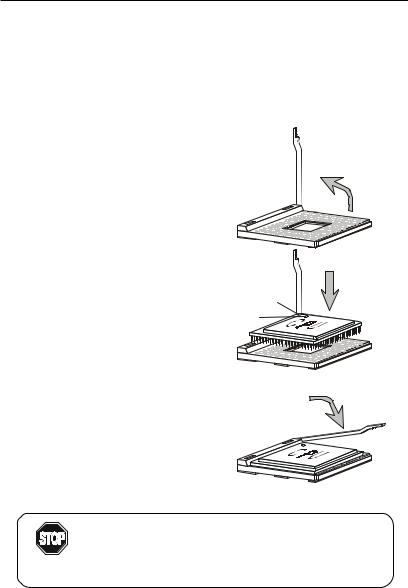
CPU Installation Procedures
1.Pull the lever sideways away from the socket. Then, raise the lever up to a 90-degree angle.
2.Look for the gold arrow. The gold arrow should point towards the lever pivot. The CPU will only fit in the correct orientation.
3.Hold the CPU down firmly, and then close the lever to complete the installation.
Open Lever
Sliding
Plate
Gold Arrow
Dot
Close
Lever
Overheating will seriously damage the CPU and system, always make sure the cooling fan can work properly to
WARNING! protect the CPU from overheating.
2-2
Hardware Setup
Installing the CPU Fan
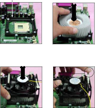
As processor technology pushes to faster speeds and higher performance, thermal management becomes increasingly important. To dissipate heat, you need to attach the CPU cooling fan and heatsink on top of the CPU. Follow the instructions below to install the Heatsink/Fan:
1.Locate the CPU and its retention mechanism on the motherboard.
retention mechanism
2.Position the heatsink onto the retention mechanism.
3.Mount the fan on top of the heatsink. Press down the fan until its four clips get wedged in the holes of the retention mechanism.
4.Press the two levers down to fasten the fan. Each lever can be pressed down in only ONE direction.
levers
2-3
Chapter 2
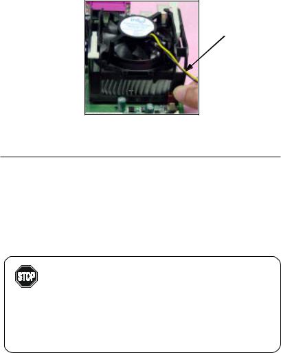
5.Connect the fan power cable from the mounted fan to the 3-pin fan power connector on the board.
fan power cable
CPU Core Speed Derivation Procedure
If |
CPUClock |
= |
100MHz |
|
Core/Bus ratio |
= |
14 |
then |
CPU core speed |
= |
Host Clock x Core/Bus ratio |
|
|
= |
100MHzx14 |
|
|
= |
1.4GHz |
Overclocking
This motherboard is designed to support overclocking.
However, please make sure your components are able to WARNING! tolerate such abnormal setting, while doing overclocking.
Any attempt to operate beyond product specifications is not recommended. We do not guarantee the damages or risks caused by inadequate operation or beyond product specifications.
2-4
Hardware Setup
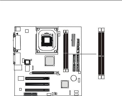
Memory
The mainboard provides 2 slots for 184-pin, 2.5V unbuffered DDR DIMM with 4 memory banks. You can install PC1600/PC2100 DDR/PC2700 SDRAM modules on the DDR DIMM slots (DDR 1~2). To operate properly, at least one DIMM module must be installed.
DDR DIMM Slots
Introduction to DDR SDRAM
DDR (Double Data Rate) SDRAM is similar to conventional SDRAM, but doubles the rate by transferring data twice per cycle. It uses 2.5 volts as opposed to 3.3 volts used in SDR SDRAM, and requires 184-pin DIMM modules rather than 168-pin DIMM modules used by SDR SDRAM. Three types of DDR SDRAM are available at the time of writing: PC1600, PC2100 and PC2700.
The following table shows the clock and peak bandwidth of each type of DDR SDRAM module:
|
PC2700 |
PC2100 |
PC1600 |
|
(DDR333) |
(DDR266) |
(DDR200) |
|
|
|
|
Clock |
166MHz |
133MHz |
100MHz |
|
|
|
|
Peak |
|
|
|
Bandwidth |
2666MB/s |
2133MB/s |
1600MB/s |
|
|
|
|
2-5
Chapter 2
DDR Module Combination
You can install either single-sided or double-sided 184-pin DDR DIMM modules into DDR DIMM slots to meet your needs. Different from the SDR DIMM, the DDR DIMM has only one notch on the center of module. The number of pins on either side of the breaks are different. The module will only fit in the right orientation.
You can install memory modules in any combination as follows:
Slot |
Momory Module |
Total Memory |
|
|
|
Slot 1 |
64MB, 128MB, 256MB, |
64MB~1GB |
(Bank 0 & 1) |
512MB, 1GB |
|
|
|
|
Slot 2 |
64MB, 128MB, 256MB, |
64MB~1GB |
(Bank 2 & 3) |
512MB, 1GB |
|
|
|
|
Maximum System Memory Supported |
64MB~2GB |
|
|
|
|
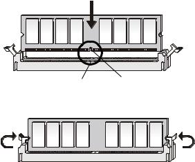
Installing DDR Modules
1.The DDR DIMM has only one notch on the center of module. The module will only fit in the right orientation.
2.Insert the DIMM memory module vertically into the DIMM slot. Then push it in.
Volt notch
3. The plastic clip at each side of the DIMM slot will automatically close.
2-6

Hardware Setup
Power Supply
The mainboard supports ATX power supply for the power system. Before inserting the power supply connector, always make sure that all components are installed properly to ensure that no damage will be caused.
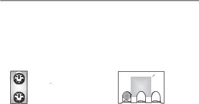
ATX 20-Pin Power Connector: CONN1
This connector allows you to connect to an ATX power supply. To connect to the ATX power supply, make sure the plugs of the power supply is inserted in the proper orientation and the pins are aligned. Then push down the power supply firmly into the connector. The power connector supports instant power on function which means that system will boot up immediately when the power supply connector is inserted on the board.
ATX 12V Power Connector: JPW1
This 12V power connector is used to provide power to the CPU.
JPW1
3 4
1  2
2
11 |
1 |
20 |
10 |
|
CONN1 |
JPW1 Pin Definition
PIN |
SIGNAL |
|
|
1 |
GND |
2 |
GND |
3 |
12V |
4 |
12V |
|
|
CONN1 Pin Definition
PIN |
SIGNAL |
PIN |
SIGNAL |
1 |
3.3V |
11 |
3.3V |
2 |
3.3V |
12 |
-12V |
3 |
GND |
13 |
GND |
4 |
5V |
14 |
PS_ON |
5 |
GND |
15 |
GND |
6 |
5V |
16 |
GND |
7 |
GND |
17 |
GND |
8 |
PW_OK |
18 |
-5V |
9 |
5V_SB |
19 |
5V |
10 |
12V |
20 |
5V |
|
|
|
|
2-7
Chapter 2
Back Panel
The Back Panel provides the following connectors:
For SiS 650 Chipset
|
Mouse |
Parallel Port |
|
Midi/Joystick Lan Jack |
||||||||||
|
|
|
|
|
|
|
|
|
|
|
|
|
|
|
|
|
|
|
|
|
|
|
|
|
|
|
|
|
|
|
|
|
|
|
|
|
|
|
|
|
|
|
|
|
|
|
|
|
|
|
|
|
|
|
|
|
|
|
|
|
|
|
|
|
|
|
|
|
|
|
|
|
|
|
|
|
|
|
|
|
|
|
|
|
|
|
|
|
|
|
|
|
|
|
|
|
|
|
|
|
|
|
|
|
|
|
|
|
|
|
|
|
|
|
|
|
|
|
|
|
|
|
|
|
|
|
|
|
|
|
|
|
|
|
|
|
|
|
|
|
|
|
|
|
|
|
|
|
|
|
|
|
|
|
|
|
|
|
|
|
|
|
|
|
|
|
|
|
|
|
|
|
|
|
|
|
|
|
|
Keyboard COM A |
VGA |
L-out L-in MIC USB Ports |
For SiS 645 Chipset
Mouse |
Parallel Port |
Midi/Joystick Lan Jack |
Keyboard COM A |
COM B |
L-out L-in MIC USB Ports |
2-8
Hardware Setup
Keyboard Connector: JKBMS1
The mainboard provides a standard PS/2® keyboard mini DIN connector for attaching a PS/2® keyboard. You can plug a PS/2® keyboard directly into this connector.
6 


 5
5
4 |
3 |
2 1
PS/2 Keyboard
(6-pin Female)
Pin Definition
PIN |
SIGNAL |
DESCRIPTION |
|
|
|
1 |
Keyboard DATA |
Keyboard DATA |
2 |
NC |
No connection |
3 |
GND |
Ground |
4 |
VCC |
+5V |
5 |
KeyboardClock |
Keyboardclock |
6 |
NC |
No connection |
|
|
|
Mouse Connector: JKBMS1
The mainboard provides a standard PS/2® mouse mini DIN connector for attaching a PS/2® mouse. You can plug a PS/2® mouse directly into this connector. The connector location and pin assignments are as follows:
6 


 5
5
4 |
3 |
21
PS/2 Mouse
(6-pin Female)
Pin Definition
PIN |
SIGNAL |
DESCRIPTION |
|
|
|
1 |
Mouse DATA |
Mouse DATA |
2 |
NC |
No connection |
3 |
GND |
Ground |
4 |
VCC |
+5V |
5 |
Mouse Clock |
Mouse clock |
6 |
NC |
No connection |
|
|
|
2-9
 Loading...