


3200 Master Series
MS-9656 (V1.X) Server Board
G52-96561X2
i

Copyright Notice
The material in this document is the intellectual property of M ICRO-STAR INTERNATIONAL. We take every care in the preparation of this document, but no guarantee is given as to the correctness of its contents. Our products are under continual improvement and we reserve the right to make changes without notice.
Trademarks
All trademarks are the properties of their respective owners.
NVIDIA, the NVIDIA logo, DualNet, and nForce are registered trademarks or trademarks of NVIDIA Corporation in the United States and/or other countries.
AMD, Athlon™, Athlon™ XP, Thoroughbred™, and Duron™ are registered trademarks of AMD Corporation.
Intel® and Pentium® are registered trademarks of Intel Corporation.
PS/2 and OS®/2 are registered trademarks of International Business Machines Corporation.
Windows® 95/98/2000/NT/XP are registered trademarks of Microsoft Corporation. Netware® is a registered trademark of Novell, Inc.
Award® is a registered trademark of Phoenix Technologies Ltd. AMI® is a registered trademark of American Megatrends Inc.
Revision History
Revision |
Revision History |
Date |
V1.1 |
Updating the Northbridge |
February 2008 |
Technical Support
If a problem arises with your system and no solution can be obtained from the user’s manual, please contact your place of purchase or local distributor. Alternatively, please try the following help resources for further guidance.
 Visit the MSI website at http://global.msi.com.tw/index.php? func=faqIndex for FAQ, technical guide, BIOS updates, driver updates, and other information.
 Contact our technical staff at http://support.msi.com.tw/.
ii

Safety Instructions
1.Always read the safety instructions carefully.
2.Keep this User’s Manual for future reference.
3.Keep this equipment away from humidity.
4.Lay this equipment on a reliable flat surface before setting it up.
5.The openings on the enclosure are for air convection hence protects the equipment from overheating. DO NOT COVER THE OPENINGS.
6.Make sure the voltage of the power source and adjust properly 110/220V before connecting the equipment to the power inlet.
7.Place the power cord such a way that people can not step on it. Do not place anything over the power cord.
8.Always Unplug the Power Cord before inserting any add-on card or module.
9.All cautions and warnings on the equipment should be noted.
10.Never pour any liquid into the opening that could damage or cause electrical shock.
11.If any of the following situations arises, get the equipment checked by service personnel:
†The power cord or plug is damaged.
†Liquid has penetrated into the equipment.
†The equipment has been exposed to moisture.
†The equipment does not work well or you can not get it work according to User’s Manual.
†The equipment has dropped and damaged.
†The equipment has obvious sign of breakage.
12.DONOT LEAVETHIS EQUIPMENT INANENVIRONMENT UNCONDITIONED, STORAGE TEMPERATURE ABOVE 600 C (1400F), IT MAYDAMAGE THE EQUIPMENT.
CAUTION: Danger of explosion if battery is incorrectly replaced. Replace only with the same or equivalent type recommended by the manufacturer.
iii

FCC-B Radio Frequency Interference Statement
This equipment has been tested and found to comply with the limits for a Class B digital device, pursuant to Part
15 of the FCC Rules. These limits are designed to provide reasonable protection against harmful interference in a residential installation. This equipment generates, uses and can radiate radio frequency energy and, if not installed and used in accordance with the instructions, may cause harmful interference to radio communications. However, there is no guarantee that interference will not occur in a particular installation. If this equipment does cause harmful interference to radio or television reception, which can be determined by turning the equipment off and on, the user is encouraged to try to correct the interference by one or more of the measures listed below.
†Reorient or relocate the receiving antenna.
†Increase the separation between the equipment and receiver.
†Connect the equipment into an outlet on a circuit different from that to which the receiver is connected.
†Consult the dealer or an experienced radio/television technician for help.
Notice 1
The changes or modifications not expressly approved by the party responsible for compliance could void the user’s authority to operate the equipment.
Notice 2
Shielded interface cables and A.C. power cord, if any, must be used in order to comply with the emission limits.
VOIR LANOTICE D’INSTALLATIONAVANT DE RACCORDER AU RESEAU.
Micro-Star International
MS-9656
This device complies with Part 15 of the FCC Rules. Operation is subject to the following two conditions:
(1)this device may not cause harmful interference, and
(2)this device must accept any interference received, including interference that may cause undesired operation.
iv

WEEE (Waste Electrical and Electronic Equipment) Statement
v

vi

vii
|
CONTENTS |
|
Copyright |
Notice .............................................................................................................. |
ii |
Trademarks ....................................................................................................................... |
ii |
|
Revision |
History .............................................................................................................. |
ii |
Technical |
Support ........................................................................................................... |
ii |
Safety Instructions ......................................................................................................... |
iii |
|
FCC-B Radio Frequency Interference Statement ........................................................ |
iv |
|
WEEE (Waste Electrical and Electronic Equipment) Statement .................................... |
v |
|
Chapter 1 Getting Started ..................................................................................... |
1-1 |
|
Mainboard Specifications ................................................................................... |
1-2 |
|
Mainboard Layout ................................................................................................ |
1-4 |
|
Chapter 2 Hardware Setup .................................................................................... |
2-1 |
|
Quick Components Guide .................................................................................... |
2-2 |
|
CPU (Central Processing Unit) ............................................................................ |
2-3 |
|
Memory................................................................................................................. |
2-7 |
|
Power Supply ...................................................................................................... |
2-9 |
|
Back Panel I/O .................................................................................................... |
2-10 |
|
Connector ........................................................................................................... |
2-11 |
|
Jumper ................................................................................................................ |
2-18 |
|
Slot ...................................................................................................................... |
|
2-19 |
Chapter 3 BIOS Setup ............................................................................................. |
3-1 |
|
Entering Setup ..................................................................................................... |
3-2 |
|
The Menu Bar ...................................................................................................... |
3-4 |
|
Main |
...................................................................................................................... |
3-5 |
Advanced ............................................................................................................ |
3-6 |
|
Boot |
.................................................................................................................... |
3-20 |
Security .............................................................................................................. |
3-23 |
|
Chipset ............................................................................................................... |
3-24 |
|
Exit ...................................................................................................................... |
|
3-26 |
Appendix A Intel ICH9R SATA RAID ..................................................................... |
A-1 |
|
ICH9R Introduction ............................................................................................... |
A-2 |
|
BIOS Configuration .............................................................................................. |
A-3 |
|
Installing Driver .................................................................................................... |
A-9 |
|
Installing Software ............................................................................................ |
A-11 |
|
RAID Migration Instructions ............................................................................... |
A-15 |
|
Degraded RAID Array ........................................................................................ |
A-22 |
|
viii

Getting Started
Chapter 1
Getting Started
Thank you for choosing the 3200 Master Series (MS9656 V1.X), an excellent server board from MSI.
Based on the innovative Intel® 3210 / 3200 & ICH9R chipsets for optimal system efficiency, the 3200 Master accommodates the latest Dual-Core Intel® Xeon® processor 3000 series, Quad-Core Intel® Xeon® processor 3200 series, Wolfdale and Yorkfield processors in LGA775 package and supports up to four 240-pin DDR2 667/800 DIMM slots to provide the maximum of 8GB memory capacity.
In the entry-level and mid-range market segment, the 3200 Master Series can provide a high-performance solution for today’s front-end and general purpose server, as well as in the future.
1-1

 MS-9656 Server Board
Mainboard Specifications
 Processor
-Dual-Core Intel Xeon processor 3000 series, Quad-Core Intel Xeon processor 3200 series, Wolfdale and Yorkfield processors in LGA775 package
 FSB
FSB
- 1333/ 1066/ 800 MHz
 Chipset
- Northbridge: Intel 3210 / 3200 chipset
(NOTE: 3210 supports either two PCI Express x8 slots or one PCI Express x16 slot. 3200 supports one PCI Express x8 slot. Neither 3210 nor 3200 supports PCI Express graphics.)
- Southbridge: Intel ICH9R chipset
 M emory
-4 DDR2 667/800 DIMM slots (240pin / 1.8V)
-Up to 8GB memory capacity
 LAN (Optional)
-For mainboards with IPMI chip:
Intel 82573V Gigabit Ethernet controller (LAN1) & Intel 82566DM Gigabit Ethernet controller (LAN2)
-For mainboards without IPMI chip:
Intel 82573L Gigabit Ethernet controller (LAN1) & Intel 82566DM Gigabit Ethernet controller (LAN2)
 Floppy
-1 floppy port
-Supports 1 FDD with 360KB, 720KB, 1.2MB, 1.44MB and 2.88MB
 IDE
IDE
-1 IDE port by ITE IT8213F
-Supports Ultra DMA 66/100/133 mode
-Supports PIO, Bus Master operation mode
 SATA
SATA
-6 SATAII ports by ICH9R
-Supports storage and data transfers at up to 300MB/s
 RAID
RAID
- Supports RAID 0/ 1/ 0+1/ 5 or JBOD mode
1-2
Getting Started
Graphics
-XGI Z7 graphics controller
-Onboard 16MB Video SDRAM
IPMI (Optional)
- Hitachi H8S/2168 IPMI microcontroller
Connectors
 Back Panel
-1 PS/2 mouse port
-1 PS/2 keyboard port
-2 USB 2.0 ports
-1 serial port
-1 VGA port
-2 Gigabit LAN jacks
 Onboard Connectors
-3 proprietary front panel connectors (optional)
-3 USB 2.0 connectors (6 ports)
-1 serial port connector
-1 TPM connector
-1 SPI Flash ROM connector (for debugging)
-1 chassis intrusion connector
Slots
-1 PCI Express x16 slot (with x8 signal)
-1 PCI Express x4 slot
-4 PCI slots (supports 3.3V/ 5V PCI bus interface)
Regulations
- FCC, CE
Form Factor
- ATX form factor 12" x 9.6"
1-3

 MS-9656 Server Board
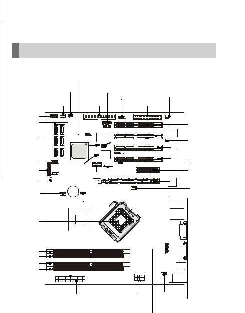
Mainboard Layout
|
COM2 |
|
JAPP2 |
|
JUSB4 |
|
SYS_FAN1 |
|
|
|
|
|
|
||||
|
|
|
|
|
FDD1 |
|
|
|
|
|
FRONT_FAN1 |
|
|
|
|
||
|
|
|
|
|
|
|
||
|
|
|
J_IDE1 |
|
|
|
|
|
|
|
|
FPC1 |
|
|
|
|
|
|
SATA1 |
SATA2 |
JSPI1 |
JTPM1 |
|
PCI1 |
|
|
|
|
|
|
|
|
|||
|
|
|
|
|
|
|
||
|
|
|
|
ITE |
|
|
|
|
|
SATA3 |
SATA4 |
IT8213F |
|
PCI2 |
|
|
|
|
J_BOOT3 J_IPMB1 |
|
|
|
||||
|
|
|
JINT1 |
|
||||
|
SATA5 |
SATA6 |
Intel |
|
|
|
|
|
|
ICH9R |
|
J_ICMB1 |
PCI3 |
|
XGI |
||
|
|
BMC |
|
|||||
|
|
|
|
|
Z7 |
|||
|
J_SMBUS1 |
Chip |
|
|
|
|||
|
|
|
|
|
|
|
||
|
|
|
|
|
|
|
|
|
|
|
|
J1 |
J_BOOT2 |
|
PCI4 |
|
|
|
JUSB3 |
|
|
|
|
|||
JAPP3 |
J_BOOT1 |
|
PCIE1 |
|
|
|||
JUSB2 |
|
|
|
|
||||
|
|
|
|
|
|
|||
|
|
|
|
|
|
|
|
|
|
|
|
|
|
|
PCIE2 |
|
|
J_VGA_EN1 |
|
|
|
|
|
|
LAN |
|
|
|
|
|
|
|
Chip |
||
|
|
|
|
|
|
|
|
|
|
|
|
BATT |
|
|
CPU_FAN1 |
|
|
|
|
|
+ |
|
|
|
|
|
|
|
SYS_FAN2 |
J_CMOS1 |
|
|
|
|
|
|
|
|
|
|
|
|
|
|
|
|
|
|
|
|
|
|
JLAN1 |
|
|
|
Intel |
|
|
|
|
JLAN 2 |
|
|
|
|
|
|
|
|
|
|
|
|
3210 / 3200 |
|
|
|
|
|
|
|
|
|
|
|
|
|
VGA 2 |
|
|
|
|
|
|
|
JAPP1 |
|
|
|
|
|
|
|
DIMM_A1 |
|
COM1 |
|
|
|
|
|
|
|
|
|
|
|
|
|
|
|
DIMM_A2 |
|
|
|
|
|
|
|
|
DIMM_B1 |
|
JUSB1 |
|
|
|
|
|
|
|
|
|
|
|
|
|
|
|
DIMM_B2 |
|
|
|
|
|
|
|
|
REAR_FAN1 |
T: Mouse |
|
|
|
|
JPWR2 |
|
|
B: Keyboard |
||
|
|
|
|
|
|
|
||
|
|
|
|
|
|
JPWR1 |
|
|
3200 Master Series (MS-9656 V1.X) Server Board
1-4
Hardware Setup
Chapter 2
Hardware Setup
This chapter provides you with the information about hardware setup procedures. While doing the installation, be careful in holding the components and follow the installation procedures. For some components, if you install in the wrong orientation, the components will not work properly.
Use a grounded wrist strap before handling computer components. Static elec tric ity may damage the components.
2-1
 MS-9656 Server Board
Quick Components Guide
|
JSPI1, p.2-12 |
|
|
|
|
|
JAPP2, p.2-14 |
JTPM1, |
|
SYS_FAN1, |
|
||
p.2-17 |
JUSB4, |
|
|
|||
|
p.2-13 |
|
||||
|
|
|
p.2-15 |
|
|
|
|
|
J_IDE1, |
FDD1, |
|
|
|
FRONT_FAN1, |
|
|
|
|||
p.2-11 |
|
p.2-11 |
|
|
||
p.2-13 |
|
|
|
|
|
|
COM2, p.2-15 |
|
|
|
|
|
|
FPC1, p.2-13 |
|
|
|
|
|
PCI Slots, |
|
|
|
|
|
|
p.2-19 |
SATA1~6, |
|
|
J_IPMB1, p.2-16 |
|
JINT1, |
|
p.2-12 |
|
|
|
|||
J_BOOT3, |
|
p.2-13 |
||||
|
|
|
|
|||
|
p.2-18 |
|
J_ICMB1, p.2-16 |
|
||
|
|
|
|
|||
JUSB2/3, |
|
|
|
|
|
J_BOOT2, |
p.2-15 |
J_SMBUS1, |
J_BOOT1, |
|
|
p.2-16 |
|
JAPP3, p.2-14 |
|
|
PCI Express |
|||
p.2-17 |
J1, p.2-16 |
p.2-16 |
|
|
||
J_VGA_EN1, |
|
|
Slots, p.2-19 |
|||
|
|
|
|
|
|
|
p.2-18 |
|
|
|
|
|
CPU_FAN1, |
SYS_FAN2, |
|
|
|
|
|
|
|
|
|
|
|
p.2-13 |
|
p.2-13 |
|
|
|
|
|
|
J_CMOS1, |
|
|
|
|
|
|
p.2-18 |
|
|
|
|
|
|
CPU, p.2-3 |
|
|
|
|
|
|
|
JPWR2, |
|
JPWR1, |
REAR_FAN1, |
|
|
DIMM Slots, |
|
p.2-13 |
Back Panel |
|||
p.2-9 |
|
p.2-9 |
|
|
||
p.2-7 |
|
|
|
|
I/O, p.2-10 |
|
|
|
|
|
JAPP1, p.2-14 |
|
|
2-2 |
|
|
|
|
|
|
Hardware Setup
CPU (Central Processing Unit)
This mainboard supports dual-core Intel® Xeon® processor 3000 series, quad-core Intel® Xeon® processor 3200 series, Wolfdale and Yorkfield processors in LGA775 package. W hen you install the CPU, make sure that you install the cooler to prevent overheating. If you do not have the CPU cooler, consult your dealer before turning on the computer.
Important
Overheating
Overheating will seriously damage the CPU and system. Always make sure the cooling fan can work properly to protect the CPU from overheating. Make sure that you apply an even layer of thermal paste (or thermal tape) between the CPU and the heatsink to enhance heat dissipation.
Replaceing the CPU
While replacing the CPU, always turn off the power supply or unplug the power supply’s power cord from the grounded outlet first to ensure the safety of CPU.
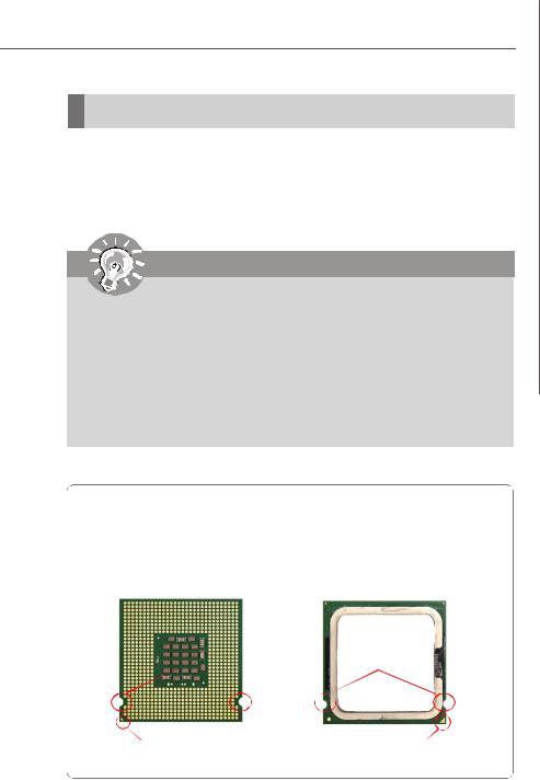
Introduction to LGA 775 CPU
The pin-pad side of LGA 775 CPU.
The surface of LGA 775 CPU. Remember to apply some thermal paste on it for better heat dispersion.
Alignment Key |
Alignment Key |
Yellow triangle is the Pin 1 indicator |
Yellow triangle is the Pin 1 indicator |
|
2-3

 MS-9656 Server Board
CPU & Cooler Installation
When you are installing the CPU, make sure the CPU has a cooler attached on the top to prevent overheating. Meanwhile, do not forget to apply some thermal paste on CPU before installing the heat sink/cooler fan for better heat dispersion.
Follow the steps below to install the CPU & cooler correctly. Wrong installation will cause the damage of your CPU & mainboard.
1.The CPU socket has a plastic cap on it to protect the contact from damage. Before you install the CPU, always cover it to protect the socket pin.
2.Remove the cap from lever hinge side (as the arrow shows).
3. The pins of socket reveal. |
4. Open the load lever. |
Important
1.Confirm if your CPU cooler is firmly installed before turning on your system.
2.Do not touch the CPU socket pins to avoid damaging.
3.The availability of the CPU land side cover depends on your CPU packing.
2-4
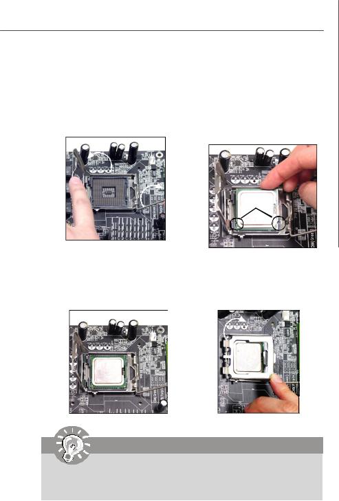
5.Lift the load lever up and open the load plate.
Hardware Setup
6.After confirming the CPU direction for correct mating, put down the CPU in the socket housing frame. Be sure to grasp on the edge of the CPU base. Note that the alignment keys are matched.
alignment key
7.Visually inspect if the CPU is seated well into the socket. If not, take out the CPU with pure vertical motion and reinstall.
8.Cover the load plate onto the package.
Important
Mainboard photos shown in this section are for demonstration of the CPU/ cooler installation only. The appearance of your mainboard may vary depending on the model you purchase.
2-5

 MS-9656 Server Board
9.Press down the load lever lightly onto the load plate, and then secure the lever with the hook under retention tab.
11.Press the four hooks down to fasten the cooler. Then rotate the locking switch (refer to the correct direction marked on it) to lock the hooks.
locking switch
10.Align the holes on the mainboard with the heatsink. Push down the cooler until its four c lips get wedged into the holes of the mainboard.
12.Turn over the mainboard to confirm that the clip-ends are correctly inserted.
Important
1.Read the CPU status in BIOS (Chapter 3).
2.Whenever CPU is not installed, always protect your CPU socket pin with the plastic cap covered to avoid damage.
2-6

Hardware Setup
Memory
These DIMM slots are intended for system memory modules.
DDR2
240-pin, 1.8V
64x2=128 pin |
56x2=112 pin |
Dual-Channel Mode Population Rule
In Dual-Channel mode, the memory modules can transmit and receive data with two data bus lines simultaneously. Dual-Channel mode is enabled when the installed memory capacities of both DIMM channels are equal. If different speed DIMMs are used between channels, the slowest memory timing will be used.
Dual-Channel mode can be achieved with two, three or four DIMMs. To achieve DualChannel mode, the following conditions must be met:
*Matched DIMM configuration in each channel
*Same Density (128MB, 256MB, 512MB, etc.)
*Matched in both Channel A and Channel B memory channels
*Populate symmetrical memory slots (Slot 1 or Slot 2)
Configurations that do not match the above conditions will revert to Single-Channel mode.
2 DIMMs
1GB |
DIMM_A1 |
|
DIMM_A2 |
1GB |
DIMM_B1 |
|
DIMM_B2 |
3 DIMMs |
|
512MB |
DIMM_A1 |
512MB |
DIMM_A2 |
1GB |
DIMM_B1 |
|
DIMM_B2 |
4 DIMMs |
|
512MB |
DIMM_A1 |
1GB |
DIMM_A2 |
512MB |
DIMM_B1 |
1GB |
DIMM_B2 |
|
Installed |
|
Empty |
2-7
 MS-9656 Server Board
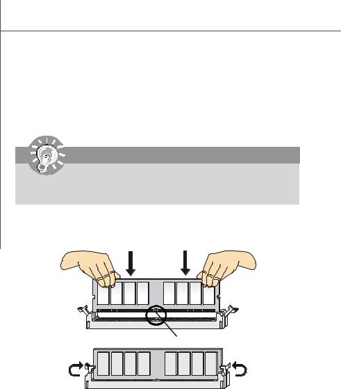
Installing Memory Modules
1.The memory module has only one notch on the center and will only fit in the right orientation.
2.Insert the memory module vertically into the DIMM slot. Then push it in until the golden finger on the memory module is deeply inserted in the DIMM slot.
Important
You can barely see the golden finger if the memory module is properly inserted in the DIMM slot.
3. The plastic clip at each side of the DIMM slot will automatically close.
Volt Notch
Notch
2-8
Hardware Setup
Power Supply
24-Pin System Power Connector: JPWR2
This connector allows you to connect a 24-pin power supply. To connect the 24-pin power supply, make sure the power supply connector is inserted in the proper orientation and the pins are aligned. Then push down the power supply firmly into the connector.
You may use the 20-pin power supply as well. If you’d like to use the 20-pin power supply, please align your power supply connector with pin 1 & pin 13. There is also a foolproof design on pin 11, 12, 23 & 24 to avoid wrong installation.
Pin Definition
pin 12 
pin 13
|
|
|
|
|
JPWR2 |
|
PIN |
SIGNAL |
PIN |
SIGNAL |
|||||||||||
|
|
|
|
|
|
1 |
+3.3V |
13 |
+3.3V |
||||||||||||
|
|
|
|
|
|
|
|
|
|
|
|
|
|
|
|
|
|
||||
24 |
|
|
|
|
|
|
|
|
|
|
|
|
|
|
|
|
13 |
2 |
+3.3V |
14 |
-12V |
|
|
|
|
|
|
|
|
|
|
|
|
|
|
|
|
3 |
GND |
15 |
GND |
||
12 |
|
|
|
|
|
|
|
|
|
|
|
|
|
|
|
|
1 |
||||
|
|
|
|
|
|
|
|
|
|
|
|
|
|
|
|
4 |
+5V |
16 |
PS-ON# |
||
|
|
|
|
|
|
|
|
|
|
|
|
|
|
|
|
|
|
||||
|
|
|
|
|
|
|
|
|
|
|
|
|
|
|
|
|
|
5 |
GND |
17 |
GND |
|
|
|
|
|
|
|
|
|
|
|
|
|
|
|
|
|
|
6 |
+5V |
18 |
GND |
|
|
|
|
|
|
|
|
|
|
|
|
|
|
|
|
|
|
7 |
GND |
19 |
GND |
|
|
|
|
|
|
|
|
|
|
|
|
|
|
|
|
|
|
8 |
PWROK |
20 |
Res |
|
|
|
|
|
|
|
|
|
|
|
|
|
|
|
|
|
|
9 |
5VSB |
21 |
+5V |
|
|
|
|
|
|
|
|
|
|
|
|
|
|
|
|
|
|
10 |
+12V |
22 |
+5V |
|
|
|
|
|
|
|
|
|
|
|
|
|
|
|
|
|
|
11 |
+12V |
23 |
+5V |
|
|
|
|
|
|
|
|
|
|
|
|
|
|
|
|
|
|
12 |
+3.3V |
24 |
GND |
8-Pin CPU Power Connector: JPWR1
This connector provides 12V power output to the CPU.
|
|
|
Pin Definition |
|
|
|
JPWR1 |
PIN |
SIGNAL |
PIN |
SIGNAL |
1 |
4 |
1 |
GND |
5 |
+12V |
5 |
8 |
2 |
GND |
6 |
+12V |
|
|
3 |
GND |
7 |
+12V |
|
|
4 |
GND |
8 |
+12V |
Important
1.Make sure that all connectors are connected to proper power supplies to ensure stable operation of the mainboard.
2.Power supply of 350 watts (and above) is highly recommended for system stability.
2-9

 MS-9656 Server Board
Back Panel I/O
Mouse
Keyboard USB Ports |
Serial Port |
VGA Port |
LAN Jacks |
 Mouse/Keyboard
The standard PS/2® mouse/keyboard DIN connector is for a PS/2® mouse/keyboard.
 USB Port
The USB (Universal Serial Bus) port is for attaching USB devices such as keyboard, mouse, or other USB-compatible devices.
 Serial Port
The serial port is a 16550A high speed communications port that sends/ receives 16 bytes FIFOs. You can attach a serial mouse or other serial devices directly to the connector.
 VGA Port
The DE-15 female connector is provided for monitor.
 LAN
LAN
The standard RJ-45 LAN jack is for connection to the Local Area Network (LAN). You can connect a network cable to it.
Link/Active Indicator |
Mode Indicator |
|
|
|
RJ-45 LAN Jack |
LED |
Color |
LED State |
Condition |
|
|
Off |
LAN link is not established. |
Left |
Orange |
On (steady state) |
LAN link is established. |
|
|
On (brighter & pulsing) The computeris communicating with another computer on the LAN. |
|
|
Green |
Off |
10 Mbit/sec data rate is selected. |
Right |
|
On |
100 Mbit/sec data rate is selected. |
|
Orange |
On |
1000 Mbit/sec data rate is selected. |
2-10
Hardware Setup
Connector
Floppy Disk Drive Connector: FDD1
This connector supports 360KB, 720KB, 1.2MB, 1.44MB or 2.88MB floppy disk drive.
FDD1
IDE Connector: J_IDE1
This connector supports IDE hard disk drives, optical disk drives and other IDE devices.
J_IDE1
Important
If you install two IDE devices on the same cable, you must configure the drives separately to master / slave mode by setting jumpers. Refer to IDE device’s documentation supplied by the vendors for jumper setting instructions.
2-11
 MS-9656 Server Board
SPI Flash ROM Connector: JSPI1
This connector is used to flash SPI flash ROM.
Pin Definition
Pin
|
JSPI1 |
1 |
|
2 |
10 |
||
|
|||
1 |
9 |
3 |
|
|
|
5 |
|
|
|
7 |
|
|
|
9 |
Description |
Pin |
Description |
VCC3_SB |
2 |
VCC3_SB |
SPI_MISO_F |
4 |
SPI_MOSI_F |
SPI_CS0_F# |
6 |
SPI_CLK_F |
GND |
8 |
GND |
SPI_HOLD# |
10 |
NC |
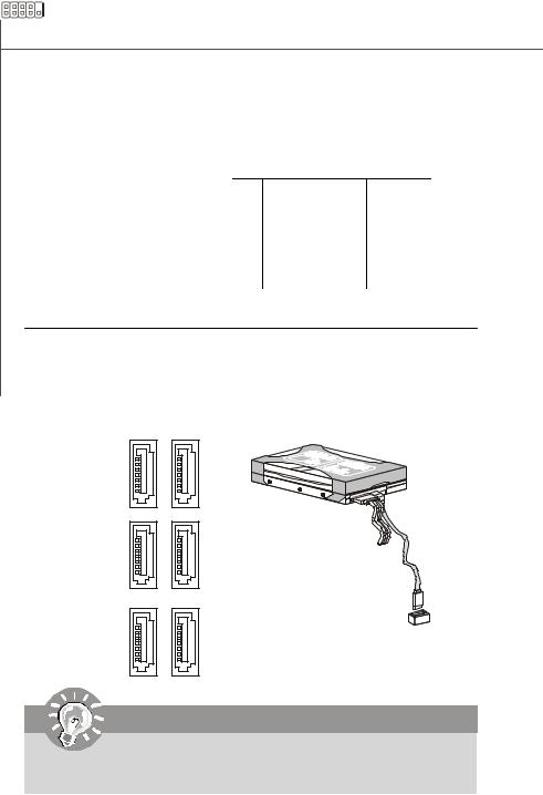
Serial ATA Connector: SATA1 ~ SATA6
This connector is a high-speed Serial ATA interface port. Each connector can connect to one Serial ATA device.
SATA1 SATA2
SATA3 SATA4
SATA5 SATA6
Important
Please do not fold the Serial ATA cable into 90-degree angle. Otherwise, data loss may occur during transmission.
2-12

Hardware Setup
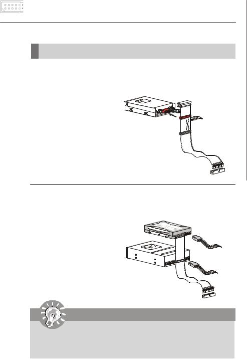
DVD/CD-ROM Connector: FPC1 (Optional)
This connector is designed to connect slim DVD/CD-ROM drive.
FPC1
Chassis Intrusion Switch Connector: JINT1
This connector connects to the chassis intrusion switch cable. If the chassis is opened, the chassis intrusion mechanism will be activated. The system will record this status and show a warning message on the screen. To clear the warning, you must enter the BIOS utility and clear the record.
CINTRU 
 1
1
GND 
 2
2
JINT1
Fan Power Connector:
CPU_FAN1, SYS_FAN1/2, FRONT_FAN1, REAR_FAN1
The fan power connectors support system cooling fan with +12V. When connecting the wire to the connectors, always note that the red wire is the positive and should be connected to the +12V; the black wire is Ground and should be connected to GND. If the mainboard has a System Hardware Monitor chipset onboard, you must use a specially designed fan with speed sensor to take advantage of the CPU fan control.
OCES
TNSN+G
ORO21N
LRVD
CPU_FAN1, SYS_FAN1, FRONT_FAN1
SYS_FAN2, REAR_FAN1
CONTROL SENSOR +12V GND
Important
1.Please refer to the recommended CPU fans at processor’s official website or consult the vendors for proper CPU cooling fan.
2.Users are suggested to enter the BIOS Setup Utility to set up the Smart Fan Control function.
2-13
 Loading...