


 Loading...
Quick Start
Thank you for purchasing the MSI® MEG X570 GODLIKE motherboard. This Quick Start section provides demonstration diagrams about how to install your computer. Some of the installations also provide video demonstrations. Please link to the URL to watch it with the web browser on your phone or tablet. You may have even link to the URL by scanning the QR code.
Preparing Tools and Components
AMD® AM4 CPU
CPU Fan
Chassis
DDR4 Memory
Power Supply Unit
Graphics Card
Thermal Paste
SATA Hard Disk Drive
SATA DVD Drive
Phillips Screwdriver |
A Package of Screws |
Quick Start 1
Safety Information
yThe components included in this package are prone to damage from electrostatic discharge (ESD). Please adhere to the following instructions to ensure successful computer assembly.
yEnsure that all components are securely connected. Loose connections may cause the computer to not recognize a component or fail to start.
yHold the motherboard by the edges to avoid touching sensitive components.
yIt is recommended to wear an electrostatic discharge (ESD) wrist strap when handling the motherboard to prevent electrostatic damage. If an ESD wrist strap is not available, discharge yourself of static electricity by touching another metal object before handling the motherboard.
yStore the motherboard in an electrostatic shielding container or on an anti-static pad whenever the motherboard is not installed.
yBefore turning on the computer, ensure that there are no loose screws or metal components on the motherboard or anywhere within the computer case.
yDo not boot the computer before installation is completed. This could cause permanent damage to the components as well as injury to the user.
yIf you need help during any installation step, please consult a certified computer technician.
yAlways turn off the power supply and unplug the power cord from the power outlet before installing or removing any computer component.
yKeep this user guide for future reference.
yKeep this motherboard away from humidity.
yMake sure that your electrical outlet provides the same voltage as is indicated on the PSU, before connecting the PSU to the electrical outlet.
yPlace the power cord such a way that people can not step on it. Do not place anything over the power cord.
yAll cautions and warnings on the motherboard should be noted.
yIf any of the following situations arises, get the motherboard checked by service personnel:
Liquid has penetrated into the computer.
The motherboard has been exposed to moisture.
The motherboard does not work well or you can not get it work according to user guide.
The motherboard has been dropped and damaged.
The motherboard has obvious sign of breakage.
yDo not leave this motherboard in an environment above 60°C (140°F), it may damage the motherboard.
2 Quick Start
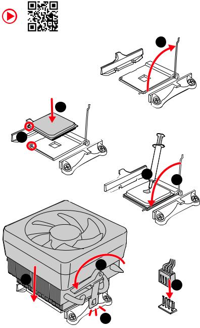
Installing a Processor
https://youtu.be/Xv89nhFk1vc |
1 |
|
3
2 


 5 4
5 4
|
8 |
6 |
9 |
|
|
|
7 |
Quick Start 3
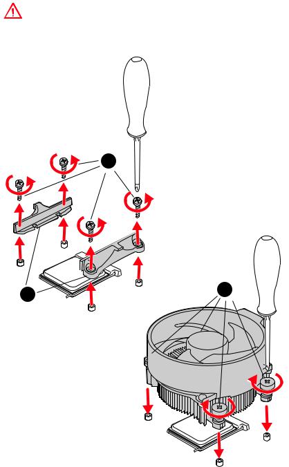
Important
If you are installing the screw-type CPU heatsink, please follow the figure below to remove the retention module first and then install the heatsink.
1
2 |
3 |
|
4 Quick Start
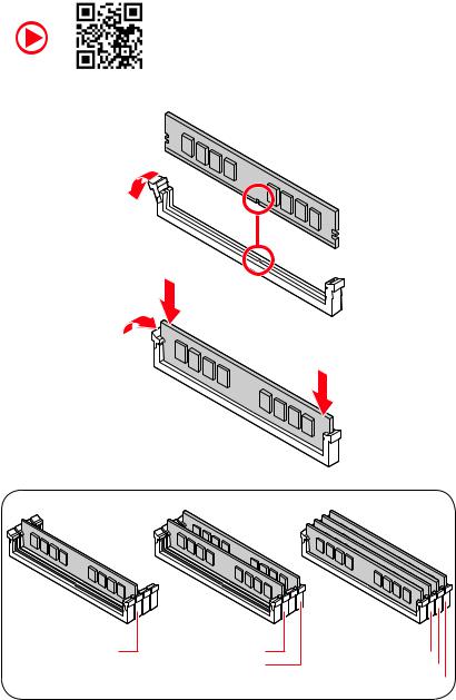
Installing DDR4 memory
http://youtu.be/T03aDrJPyQs
DIMMA2 |
DIMMA2 |
|
DIMMB2 |
DIMMA1  DIMMA2
  DIMMB1
  DIMMB2
Quick Start 5

Connecting the Front Panel Header
http://youtu.be/DPELIdVNZUI
|
|
- |
|
|
|
LED |
|
|
LED+ |
POWER |
|
|
POWER |
||
|
LED |
|
|
SW |
HDD |
||
|
|
||
POWER |
|
|
|
SW |
|
|
|
RESET |
|
|
|
|
|
|
|
|
|
|
|
|
|
||||||||
|
|
Power LED |
|
Power Switch |
|||||||||||||
|
|
|
|
|
|
|
|
|
|
|
|
|
|
|
|
|
|
|
|
|
|
|
|
|
|
|
|
|
|
|
|
|
|
|
|
|
|
|
|
+ - + - |
|
|
|
|
|
|
|||||||
|
JFP1 |
2 |
|
|
|
|
|
|
|
|
|
10 |
|
|
|||
|
|
|
|
|
|
|
|
|
|
||||||||
|
1 |
|
|
|
|
|
|
|
|
|
9 |
|
|
||||
|
|
|
|
|
|
|
|
|
|
|
|
|
|
|
|||
|
|
|
|
+ - - + |
|
|
|
Reserved |
|||||||||
|
|
|
|
|
|
|
|
|
|
|
|
|
|
|
|
|
|
|
|
|
|
|
|
|
|
|
|
|
|
|
|
||||
|
|
|
|
|
|
|
|
|
|
|
|||||||
|
|
|
HDD LED |
|
|
|
Reset Switch |
||||||||||
|
|
|
|
|
|
|
|
|
|
|
|
|
|
|
|
|
|
1 |
HDD LED + |
|
|
|
|
2 |
|
|
|
|
|
Power LED + |
|||||
|
|
|
|
|
|
|
|
|
|
|
|
|
|
|
|
|
|
3 |
HDD LED - |
|
|
|
|
4 |
|
|
|
|
|
Power LED - |
|||||
|
|
|
|
|
|
|
|
|
|
|
|
|
|
|
|
|
|
5 |
Reset Switch |
|
|
|
|
6 |
|
|
|
|
|
Power Switch |
|||||
|
|
|
|
|
|
|
|
|
|
|
|
|
|
|
|
|
|
7 |
Reset Switch |
|
|
|
|
8 |
|
|
|
|
|
Power Switch |
|||||
|
|
|
|
|
|
|
|
|
|
|
|
|
|
|
|
|
|
9 |
Reserved |
|
|
|
|
10 |
|
|
|
|
|
No Pin |
|||||
|
|
|
|
|
|
|
|
|
|
|
|
|
|
|
|
|
|
HDD LED
 POWER LED
RESETSW
HDDLED
HDD LED - HDD LED +
POWER LED - POWER LED +
6 Quick Start

Installing the Motherboard
1
 2
2


Quick Start 7
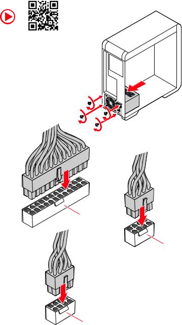
Connecting the Power Connectors
http://youtu.be/gkDYyR_83I4
ATX_PWR1
CPU_PWR1
CPU_PWR2
8 Quick Start

Installing SATA Drives
http://youtu.be/RZsMpqxythc |
1 |
|
2 |
3 |
|
5
4
Quick Start 9
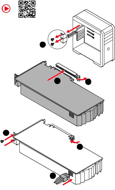
Installing a Graphics Card
http://youtu.be/mG0GZpr9w_A
1
3 |
2 |
5


 4
4
6
10 Quick Start
Connecting Peripheral Devices
Quick Start 11

Power On
1 |
2 |
3
4
12 Quick Start
Contents |
|
Quick Start ............................................................................................................. |
1 |
Preparing Tools and Components.......................................................................... |
1 |
Safety Information .................................................................................................. |
2 |
Installing a Processor............................................................................................. |
3 |
Installing DDR4 memory ........................................................................................ |
5 |
Connecting the Front Panel Header....................................................................... |
6 |
Installing the Motherboard..................................................................................... |
7 |
Connecting the Power Connectors......................................................................... |
8 |
Installing SATA Drives............................................................................................. |
9 |
Installing a Graphics Card .................................................................................... |
10 |
Connecting Peripheral Devices ............................................................................ |
11 |
Power On............................................................................................................... |
12 |
Specifications....................................................................................................... |
16 |
JCORSAIR1 Connector Specification.................................................................... |
23 |
Package contents................................................................................................. |
23 |
Block Diagram .................................................................................................... |
24 |
Rear I/O Panel...................................................................................................... |
25 |
LAN Port LED Status Table................................................................................... |
25 |
Audio Ports Configuration .................................................................................... |
25 |
Realtek Audio Console ......................................................................................... |
26 |
Installing Antennas............................................................................................... |
28 |
Overview of Components .................................................................................... |
29 |
Processor Socket.................................................................................................. |
31 |
DIMM Slots............................................................................................................ |
32 |
PCI_E1~4: PCIe Expansion Slots.......................................................................... |
33 |
M2_1~3: M.2 Slots (Key M) ................................................................................... |
36 |
SATA1~6: SATA 6Gb/s Connectors ....................................................................... |
38 |
JFP1, JFP2: Front Panel Connectors ................................................................... |
41 |
JAUD1: Front Audio Connector ............................................................................ |
41 |
CPU_PWR1~2, ATX_PWR1: Power Connectors ................................................... |
42 |
OC1: GAME BOOST Knob ..................................................................................... |
43 |
BCLK+1, BCLK-1: Base Clock Plus & Minus Button ........................................... |
44 |
V-Check Points ..................................................................................................... |
44 |
T_SEN1~2: Thermal Sensor Connectors ............................................................. |
45 |
JSLOW1: Slow Mode Booting Jumper.................................................................. |
45 |
JLN1: Low Temperature Booting Jumper............................................................ |
45 |
CPU_FAN1, PUMP_FAN1, SYS_FAN1~7: Fan Connectors................................... |
46 |
Contents 13
W_FLOW1: Water Flow Meter Connector............................................................. |
47 |
JUSB1: USB 3.2 Gen2 Type-C Connector............................................................. |
47 |
JUSB2~3: USB 3.2 Gen1 Connectors ................................................................... |
48 |
JUSB4~5: USB 2.0 Connectors............................................................................. |
48 |
JTPM1: TPM Module Connector........................................................................... |
49 |
JBAT1: Clear CMOS (Reset BIOS) Jumper ........................................................... |
49 |
JCI1: Chassis Intrusion Connector....................................................................... |
50 |
POWER1, RESET1: Power Button, Reset Button ................................................. |
50 |
BIOS_SW1: Multi-BIOS Switch ............................................................................. |
51 |
JRGB1: RGB LED connector................................................................................. |
52 |
JRAINBOW1~2: Addressable RGB LED connectors............................................. |
53 |
JCORSAIR1: CORSAIR Connector ........................................................................ |
54 |
DYNAMIC DASHBOARD ........................................................................................ |
55 |
DYNAMIC DASHBOARD Status Table ................................................................... |
55 |
Onboard LEDs...................................................................................................... |
56 |
EZ Debug LED....................................................................................................... |
56 |
Fan LEDs............................................................................................................... |
56 |
Multi-BIOS LEDs................................................................................................... |
56 |
A-XMP LED ........................................................................................................... |
57 |
JPWRLED1: LED power input............................................................................... |
57 |
CPU Power LED .................................................................................................... |
58 |
Debug Code LED................................................................................................... |
59 |
Hexadecimal Character Table .............................................................................. |
59 |
Boot Phases.......................................................................................................... |
59 |
Debug Code LED Table ......................................................................................... |
59 |
ACPI States Codes ................................................................................................ |
63 |
Installing OS, Drivers & Utilities ......................................................................... |
64 |
Installing Windows® 10......................................................................................... |
64 |
Installing Drivers .................................................................................................. |
64 |
Installing Utilities ................................................................................................. |
64 |
BIOS Setup........................................................................................................... |
65 |
Entering BIOS Setup............................................................................................. |
65 |
Resetting BIOS...................................................................................................... |
66 |
Updating BIOS....................................................................................................... |
66 |
EZ Mode ................................................................................................................ |
68 |
Advanced Mode .................................................................................................... |
70 |
SETTINGS.............................................................................................................. |
71 |
Advanced............................................................................................................... |
71 |
Boot....................................................................................................................... |
76 |
Security................................................................................................................. |
77 |
14 Contents
Save & Exit............................................................................................................ |
78 |
OC.......................................................................................................................... |
79 |
M-FLASH .............................................................................................................. |
82 |
OC PROFILE.......................................................................................................... |
83 |
HARDWARE MONITOR.......................................................................................... |
84 |
Nahimic 3............................................................................................................. |
85 |
Installation and Update ........................................................................................ |
85 |
Audio Tab .............................................................................................................. |
85 |
Microphone Tab .................................................................................................... |
86 |
Sound Tracker Tab................................................................................................ |
87 |
Settings Tab .......................................................................................................... |
87 |
Killer Control Center........................................................................................... |
88 |
Configuring Bandwidth......................................................................................... |
88 |
AMD RAID Configuration ..................................................................................... |
89 |
Enabling RAIDXpert2 Configuration Utility .......................................................... |
89 |
Initializing Disks ................................................................................................... |
90 |
Creating Arrays..................................................................................................... |
91 |
Deleting Arrays..................................................................................................... |
92 |
Installing RAID Driver........................................................................................... |
93 |
Troubleshooting .................................................................................................. |
94 |
Contents 15

Specifications
CPU |
Supports 2nd and 3rd Gen AMD Ryzen™ / Ryzen™ with |
|
Radeon™ Vega Graphics and 2nd Gen AMD Ryzen™ with |
||
|
Radeon™ Graphics Desktop Processors for Socket AM4 |
|
|
|
|
Chipset |
AMD® X570 Chipset |
|
|
|
|
|
y4x DDR4 memory slots, support up to 128GB (depending |
|
|
on the processor) |
|
|
Supports 1866/ 2133/ 2400/ 2666Mhz by JEDEC and |
|
|
2666/ 2800/ 2933/ 3000/ 3066/ 3200/ 3466/ 3600/ 3733/ |
|
|
3866/ 4000/ 4133/ 4266/ 4400/ 4533/ 4600 by A-XMP OC |
|
Memory |
mode |
|
yDual channel memory architecture |
||
|
||
|
ySupports non-ECC UDIMM memory |
|
|
ySupports ECC UDIMM memory (non-ECC mode) |
|
|
ySupports un-buffered memory |
|
|
* Please refer www.msi.com for more information on compatible memory. |
|
|
|
|
|
y3x PCIe 4.0/3.0 x16 slot (PCI_E1~3)* |
|
|
3rd Gen AMD Ryzen™ support PCIe 4.0 x16/x0/x0, x8/ |
|
|
x0/x8, x8/x4/x4 mode |
|
|
2nd Gen AMD Ryzen™ support PCIe 3.0x16/x0/x0, x8/x0/ |
|
Expansion Slot |
x8, x8/x4/x4 mode |
|
Ryzen™ with Radeon™ Vega Graphics and 2nd Gen AMD |
||
|
||
|
Ryzen™ with Radeon™ Graphics support PCIe 3.0 x8/x0/ |
|
|
x0 mode |
|
|
y1x PCIe 4.0/3.0 x16 slot (PCI_E4, supports x4 mode) |
|
|
*The speeds may vary for different devices |
|
|
|
|
Multi-GPU |
ySupports 2-Way NVIDIA® SLI™ Technology |
|
ySupports 4-Way AMD® CrossFire™ Technology |
||
|
||
|
|
|
|
Continued on next page |
16 Specifications

Continued from previous page
|
y6x SATA 6Gb/s ports (from AMD® X570 Chipset) |
|
|
y3x M.2 slots (Key M)* |
|
|
M2_1 slot (from AMD® X570 Chipset) supports PCIe |
|
|
4.0 x4 (3rd Gen AMD Ryzen™) or 3.0 x4 (2nd Gen AMD |
|
|
Ryzen™/ Ryzen™ with Radeon™ Vega Graphics and 2nd |
|
|
Gen AMD Ryzen™ with Radeon™ Graphics) and SATA |
|
|
6Gb/s 2242/ 2260/ 2280/ 22110 storage devices |
|
Storage |
M2_2 slot (from AMD® X570 Chipset) supports PCIe |
|
4.0 x4 (3rd Gen AMD Ryzen™) or 3.0 x4 (2nd Gen AMD |
||
|
Ryzen™/ Ryzen™ with Radeon™ Vega Graphics and 2nd |
|
|
Gen AMD Ryzen™ with Radeon™ Graphics) and SATA |
|
|
6Gb/s 2242/ 2260/ 2280 storage devices |
|
|
M2_3 slot (from AMD® Processor) supports PCIe 4.0 |
|
|
x4 (3rd Gen AMD Ryzen™) or PCIe 3.0 x4 (2nd Gen AMD |
|
|
Ryzen™/ Ryzen™ with Radeon™ Vega Graphics and 2nd |
|
|
Gen AMD Ryzen™ with Radeon™ Graphics) 2242/ 2260/ |
|
|
2280/ 22110 storage devices |
|
|
*The speeds may vary for different devices |
|
|
|
|
RAID |
AMD® X570 Chipset |
|
ySupports RAID 0, RAID 1 and RAID 10 |
||
|
||
|
|
|
LAN |
y1x Killer® E2600 Gigabit LAN Controller |
|
y1x Killer® E3000 2.5 Gbps LAN Controller |
||
|
||
|
Killer™ Wi-Fi 6 AX1650 Chipset |
|
Wireless LAN & |
yThe Wireless module is pre-install in the M2_4 (Key-E) slot |
|
ySupports Wi-Fi 802.11 a/b/g/n/ac/ax, dual band (2.4GHz, |
||
Bluetooth® |
||
|
5GHz) up to 2.4 Gbps speed. |
|
|
y Supports Bluetooth® 5 |
|
|
|
|
|
Continued on next page |
Specifications 17

Continued from previous page
|
yAMD® X570 Chipset |
|
3x USB 3.2 Gen2 (SuperSpeed USB 10Gbps) ports |
|
(2 Type-A ports on the back panel, 1 Type-C internal |
|
connectors) |
|
4x USB 3.2 Gen1 (SuperSpeed USB) ports through the |
|
internal USB connectors |
USB |
4x USB 2.0 (High-speed USB) ports through the internal |
USB connectors |
|
|
yAMD® Processor |
|
2x USB 3.2 Gen2 (3rd Gen AMD Ryzen™) or USB 3.2 |
|
Gen1 (2nd Gen AMD Ryzen™/ Ryzen™ with Radeon™ |
|
Vega Graphics and 2nd Gen AMD Ryzen™ with Radeon™ |
|
Graphics) Type-A and Type-C port on the back panel |
|
2x USB 3.2 Gen1 (SuperSpeed USB) Type-A ports on the |
|
back panel |
|
|
|
y2x Realtek® ALC1220 Codecs |
|
7.1-Channel High Definition Audio |
Audio |
Supports S/PDIF output |
|
yESS® E9018 Codec |
|
Supports 6.3mm Gold-plated stereo headphone out |
|
|
|
y1x Flash BIOS Button |
|
y1x Clear CMOS button |
|
y2x Wi-Fi Antenna connectors |
|
y1x PS/2 keyboard/ mouse combo port |
|
y2x USB 3.2 Gen1 Type-A ports |
Back Panel |
y2x LAN (RJ45) ports |
Connectors |
y2x USB 3.2 Gen2 Type-A ports |
|
|
|
y2x USB 3.2 Gen2 Type-A & Type-C port (depending on the |
|
processor) |
|
y1x 6.3mm Gold-plated stereo headphone jack |
|
y5x OFC audio jacks |
|
y1x Optical S/PDIF OUT connector |
|
|
|
Continued on next page |
18 Specifications

Continued from previous page
y1x 24-pin ATX main power connector
y2x 8-pin ATX 12V power connectors
y6x SATA 6Gb/s connectors
y3x M.2 slots (M-Key)
y1x USB 3.2 Gen2 Type-C port
y2x USB 3.2 Gen1 connectors (supports additional 4 USB 3.2 Gen1 ports)
y2x USB 2.0 connectors (supports additional 4 USB 2.0 ports)
y1x 4-pin CPU fan connector
Internal Connectors y1x 4-pin Water Pump connector
|
y7x 4-pin system fan connectors |
|
|
y1x 3-pin Water Flow connector |
|
|
y1x Front panel audio connector |
|
|
y2x System panel connectors |
|
|
y1x Chassis Intrusion connector |
|
|
y2x 2-pin Thermal Sensors connectors |
|
|
y1x 4-pin RGB LED connector |
|
|
y2x 3-pin RAINBOW LED connectors |
|
|
y1x 3-pin CORSAIR LED connector |
|
|
|
|
|
y1x GAME BOOST knob |
|
|
y1x BCLK+1 button |
|
Internal Buttons |
y1x BCLK-1 button |
|
|
y1x Power button |
|
|
y1x Reset button |
|
|
|
|
Switch |
y1x Multi-BIOS switch |
|
|
|
|
Jumper |
y1x Slow mode jumper |
|
y1x Low temperature booting jumper |
||
|
||
|
|
|
Debug LED |
y1x 2-Digit Debug Code LED |
|
y4x EZ Debug LED |
||
|
||
|
|
|
Display Panel |
DYNAMIC DASHBOARD |
|
yDisplays system information |
||
|
||
|
|
|
|
Continued on next page |
Specifications 19

|
Continued from previous page |
||
|
|
||
I/O Controller |
NUVOTON NCT6797 Controller Chip |
||
|
|
||
|
yCPU/System/Chipset temperature detection |
||
Hardware Monitor |
yCPU/System/Chipset fan speed detection |
||
|
yCPU/System/Chipset fan speed control |
||
|
|
|
|
Form Factor |
yE-ATX Form Factor |
|
|
y12 in. x 10.7 in. (30.5 cm x 27.2 cm) |
|||
|
|||
|
|
|
|
|
yDual BIOS |
|
|
|
y2x 256 Mb flash |
|
|
BIOS Features |
yUEFI AMI BIOS |
|
|
|
yACPI 6.1, SMBIOS 2.8 |
|
|
|
yMulti-language |
|
|
|
|
|
|
|
yDrivers |
|
|
|
yDRAGON CENTER |
|
|
|
yKiller Control Center |
|
|
Software |
yNahimic Audio |
|
|
yCPU-Z MSI GAMING |
|
||
|
|
||
|
yMSI App Player (BlueStacks) |
|
|
|
yGoogle Chrome™, Google Toolbar, Google Drive |
||
|
yNorton™ Internet Security Solution |
||
|
|
|
|
|
y DRAGON OPTIMIZATION |
|
|
|
y OC Performance |
|
|
Dragon Center |
y Hardware Monitor |
|
|
y LAN Manager |
|
||
Features |
|
||
y True Color |
|
||
|
Please refer to http://download.msi. |
||
|
y Mystic Light |
||
|
com/manual/mb/DRAGONCENTER2. |
||
|
y Live update |
pdf for more details. |
|
|
|
||
|
|
|
|
|
Continued on next page |
|
|
20 Specifications
Continued from previous page
|
yAudio |
|
|
Xtreme Audio DAC |
|
|
Nahimic 3 |
|
|
Voice Boost |
|
|
yNetwork |
|
|
GAMING LAN with Killer LAN Manager |
|
|
Killer WiFi |
|
|
Killer xTend |
|
|
2.5G LAN |
|
|
yStorage |
|
|
Lightning Gen 4 M.2 |
|
|
Triple M.2 |
|
|
yCooling |
|
|
Frozr Heatsink Design |
|
|
Zero Frozr Technology |
|
Special Features |
Propeller Blade Technology |
|
M.2 Shield Frozr |
||
|
||
|
Pump Fan |
|
|
Gaming Fan Control |
|
|
yLED |
|
|
Mystic Light 3 |
|
|
Mystic Light Infinity II |
|
|
Mystic Light Extension (RGB) |
|
|
Mystic Light Extension (RAINBOW) |
|
|
Mystic Light Extension (CORSAIR) |
|
|
Mystic Light Sync |
|
|
EZ DEBUG LED |
|
|
Dynamic Dashboard |
|
|
yProtection |
|
|
PCIe Steel Armor |
|
|
DDR4 Steel Armor |
|
|
Pre-installed IO Shielding |
|
|
|
|
|
Continued on next page |
Specifications 21
Continued from previous page
|
yPerformance |
|
Lightning Gen 4 PCI-E Slot |
|
Multi GPU – SLI Technology |
|
Multi GPU – CrossFire Technology |
|
DDR4 Boost |
|
Core Boost |
|
GAME Boost(8 modes) |
|
OC Engine(Clock gen) |
|
USB with type A+C |
|
AMD Turbo USB 3.2 Gen 2 |
|
Front USB Type-C |
|
Dual CPU Power |
Special Features |
yGamer Experience |
|
Dynamic Dashboard |
|
DRAGON CENTER |
|
GAMING HOTKEY |
|
GAMING MOUSE Control |
|
SPEED UP |
|
Total Fan Control |
|
Live Update |
|
APP Player |
|
yBIOS |
|
Click BIOS 5 |
|
Flash BIOS Button |
|
Dual BIOS |
|
|
22 Specifications

JCORSAIR1 Connector Specification
Supporting CORSAIR RGB Products |
Maximum connection |
|
|
|
|
Lighting Node PRO LED Strip |
20* |
|
* 20% brightness is recommended when the number of |
||
|
||
|
LED strips exceeds 8. |
|
|
|
|
HD120 RGB Fan |
6 |
|
|
|
|
SP120 RGB Fan |
6 |
|
|
|
|
LL120 RGB Fan |
6 |
|
|
|
Package contents
Please check the contents of your motherboard package. It should contain:
Motherboard |
MEG X570 GODLIKE |
|
|
|
|
|
|
|
SATA 6Gb/s Cables |
6 |
|
|
|
|
|
|
1 to 2 RGB LED Extension Y Cable 80cm |
1 |
|
|
|
|
|
Cable |
CORSAIR RGB LED Extension Cable 50cm |
1 |
|
|
|
||
RAINBOW RGB LED Extension Cable 80cm |
2 |
||
|
|||
|
|
|
|
|
CORSAIR to RAINBOW RGB Extension Cable 10cm |
1 |
|
|
|
|
|
|
Thermistor Cable |
2 |
|
|
|
|
|
|
Antenna Set |
1 |
|
|
|
|
|
|
M.2 Xpander-Z Gen4 |
1 |
|
|
|
|
|
|
10G Super LAN |
1 |
|
|
|
|
|
Accessories |
8.5H M.2 screws |
3 |
|
|
|
||
6.3mm Audio Adapters |
1 |
||
|
|||
|
|
|
|
|
Case Badge |
1 |
|
|
|
|
|
|
SATA Cable Labels |
1 |
|
|
|
|
|
|
Product Registration Card |
1 |
|
|
|
|
|
Application DVD |
Driver DVD |
1 |
|
|
|
|
|
|
User Manual |
1 |
|
|
|
|
|
Documentation |
Quick Guide |
1 |
|
|
|
|
|
|
Quick Installation Guide |
1 |
|
|
|
|
Important
If any of the above items are damaged or missing, please contact your retailer.
Package contents 23

Block Diagram
|
|
|
|
Front |
|
|
|
|
|
Jacks |
|
|
|
|
|
|
|
|
|
|
|
|
|
|
|||
|
|
|
|
|
|
|
|
|
|
|
|||
|
Rear |
Audio Jacks |
|
Audio |
|
|
|||||||
NUVOTON |
|
Realtek |
|
|
Realtek |
ESS |
|
||||||
6797 |
|
ALC1220 |
|
|
ALC1220 |
|
|
|
E9018 |
|
|||
|
2 Channel DDR4 Memory |
|
Processor |
|
1x M.2 |
|
Switch |
|
PCI Express Bus |
|
2x USB 3.2 Gen1 |
2x M.2 |
2x USB 3.2 Gen2 |
|
|
|
PCIE |
|
4x SATA 6Gb/s |
|
|
|
1x Killer Wi-Fi 6 AX1650 |
2x SATA 6Gb/s |
ASM |
PCH |
|
||
1061 |
|
|
|
|
|
|
ASM |
1x Killer E2600 |
|
1182 |
|
2x USB 2.0 |
ASM |
|
1042 |
|
|
4x USB 3.2 Gen1 |
|
1x Killer E3000 |
|
|
|
3x USB 3.2 Gen2 |
|
|
24 Block Diagram
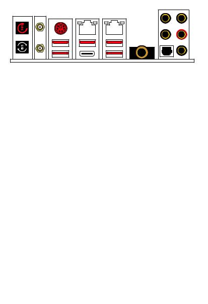
Rear I/O Panel
Wi-Fi Antenna connectors
Clear CMOS button |
PS/2 |
Gigabit |
2.5Gbps |
Audio Ports |
|
||||
|
|
LAN |
LAN |
|
|
|
|
|
USB 3.2 |
|
|
|
|
Gen2 |
Flash BIOS Button |
USB 3.2 |
|
||
Gen1 |
USB 3.2 Gen2 Type-C* |
Optical S/PDIF-Out |
||
|
||||
USB 3.2 Gen1/ |
USB 3.2 Gen2* |
6.3mm headphone port |
||
Flash BIOS Port |
||||
*USB 3.2 Gen2 (3rd Gen AMD Ryzen™) or USB 3.2 Gen1 (2nd Gen AMD Ryzen™/ Ryzen™ with Radeon™ Vega Graphics and 2nd Gen AMD Ryzen™ with Radeon™ Graphics)
yClear CMOS button - Power off your computer. Press and hold the Clear CMOS button for about 5-10 seconds to reset BIOS to default values.
yFlash BIOS Button/Port - Please refer to page 67 for Updating BIOS with Flash BIOS Button.
y6.3mm headphone port - This port is used for connecting the headphone.
LAN Port LED Status Table
Link/ Activity LED
Status |
Description |
|
|
Off |
No link |
|
|
Yellow |
Linked |
|
|
Blinking |
Data activity |
|
|
Speed LED
Status |
Gigabit LAN |
2.5Gbps LAN |
|
|
|
Off |
10 Mbps |
10 Mbps |
|
|
|
Green |
100 Mbps |
100 M/ 1G bps |
|
|
|
Orange |
1 Gbps |
2.5 Gbps |
|
|
|
Audio Ports Configuration
|
|
|
|
|
|
|
|
|
|
Audio Ports |
|
Channel |
|
|
|
|
|
|
|
|
|
|
|
|
|
|
|
|
|
|
|
|
|
|
|
|
|
|
|
|
2 |
4 |
6 |
8 |
|
|
|
|
|
|
|
|
|
|
|
|
|
|
|
|
|
|
|
|
|
|
|
|
|
Center/ Subwoofer Out |
|
|
● |
● |
|
|
|
|
|
|
|
|
|
|
|
|
|||
|
|
|
|
|
|
|
|
|
|
Rear Speaker Out |
|
● |
● |
● |
|
|
|
|
|
|
|
|
|
|
|
||||
|
|
|
|
|
|
|
|
|
|
Line-In/ Side Speaker Out |
|
|
|
● |
|
|
|
|
|
|
|
|
|
|
|
|
|
||
|
|
|
|
|
|
|
|
|
|
Line-Out/ Front Speaker Out |
● |
● |
● |
● |
|
|
|
|
|
|
|
|
|
|
|||||
|
|
|
|
|
|
|
|
|
|
Mic In |
|
|
|
|
|
|
|
|
|
|
|
|
|
|
|
|
|
|
|
|
|
|
|
|
|
|
|
|
|
|
|
|
|
|
|
|
|
|
|
|
|
|
|
|
(●: connected, Blank: empty) |
|
|
|
|
Rear I/O Panel 25
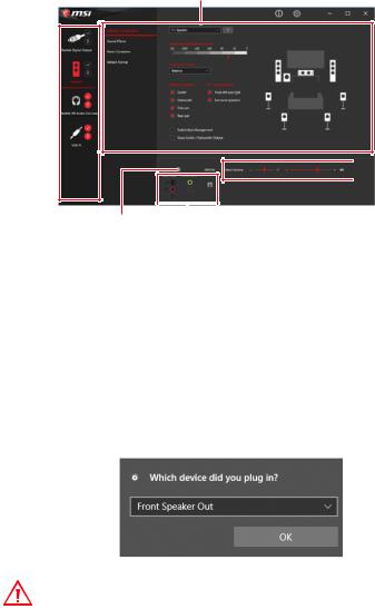
Realtek Audio Console
After Realtek Audio Console is installed. You can use it to change sound settings to get better sound experience.
Application Enhancement
Device 
Selection
 Main Volume
Connector Settings |
|
|
Jack Status |
||
yDevice Selection - allows you to select a audio output source to change the related options. The check sign indicates the devices as default.
yApplication Enhancement - the array of options will provide you a complete guidance of anticipated sound effect for both output and input device.
yMain Volume - controls the volume or balance the right/left side of the speakers that you plugged in front or rear panel by adjust the bar.
yJack Status - depicts all render and capture devices currently connected with your computer.
yConnector Settings - configures the connection settings.
Auto popup dialog
When you plug into a device at an audio jack, a dialogue window will pop up asking you which device is current connected.
Each jack corresponds to its default setting as shown on the next page.
Important
The pictures above for reference only and may vary from the product you purchased.
26 Rear I/O Panel
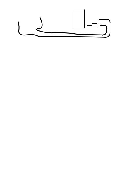
Audio jacks to headphone and microphone diagram
Audio jacks to stereo speakers diagram
AUDIO INPUT
Audio jacks to 7.1-channel speakers diagram
AUDIO INPUT
Rear |
Front |
Side |
Center/ |
|
Subwoofer |
Rear I/O Panel 27
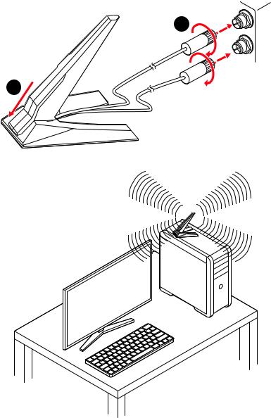
Installing Antennas
1.Combine the antenna with the base.
2.Screw two antenna cables tight to the WiFi antenna connectors as shown.
2
1
3. Place the antenna as high as possible.
28 Rear I/O Panel
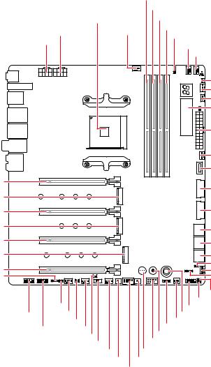
Overview of Components
PCI_E1
M2_1
PCI_E2
M2_2
PCI_E3
M2_3
PCI_E4 JRAINBOW2
CPU_PWR2 CPU_PWR1
|
DIMMA1 |
||
|
|
DIMMA2 |
|
Processor Socket |
|
DIMMB1 |
|
|
|
||
PUMP_FAN1 |
DIMMB2 |
||
JRGB1 |
|||
|
|
||
|
|
CPU_FAN1 |
|
|
|
SYS_FAN1 |
|
|
|
T_SEN1 |
|
|
|
SYS_FAN2 |
|
|
|
JCORSAIR1 |
|
|
|
DYNAMIC |
|
|
|
DASHBOARD |
|
|
|
ATX_PWR1 |
|
|
|
SYS_FAN3 |
|
|
|
JUSB1 |
|
|
|
JUSB2 |
|
|
|
JUSB3 |
|
|
|
SATA▼1▲2 |
|
|
|
SATA▼3▲4 |
|
|
|
SATA▼5▲6 |
|
|
|
JSLOW1 |
|
|
|
SYS_FAN4 |
|
|
|
JRAINBOW1 |
|
|
|
JBAT1 |
|
|
JLN1 |
JCI1 |
|
|
JFP1 |
||
JAUD1 SYS_FAN7 |
OC1 |
||
|
T_SEN2 |
W_FLOW1 |
|
|
JFP2 |
||
JTPM1 |
SYS_FAN6 |
||
POWER1 |
|||
|
JPWRLED1 |
||
|
JUSB4 |
||
|
BIOS_SW1 |
||
|
|
||
|
SYS_FAN5 |
RESET1 |
|
|
BLCK- |
BLCK+ |
|
JUSB5
Overview of Components 29

Component Contents
Port Name |
Port Type |
Page |
|
|
|
|
|
BCLK+1, BCLK-1 |
Base Clock Plus & Minus Button |
44 |
|
|
|
|
|
BIOS_SW1 |
Multi-BIOS Switch |
51 |
|
|
|
|
|
CPU_FAN1, PUMP_FAN1, |
Fan Connectors |
46 |
|
SYS_FAN1~7 |
|||
|
|
||
CPU_PWR1~2, ATX_PWR1 |
Power Connectors |
42 |
|
|
|
|
|
DIMMA1/A2/B1/B2 |
DIMM Slots |
32 |
|
|
|
|
|
DYNAMIC DASHBOARD |
OLED |
55 |
|
|
|
|
|
JAUD1 |
Front Audio Connector |
41 |
|
|
|
|
|
JBAT1 |
Clear CMOS (Reset BIOS) Jumper |
49 |
|
|
|
|
|
JCI1 |
Chassis Intrusion Connector |
50 |
|
|
|
|
|
JCORSAIR1 |
CORSAIR Connector |
54 |
|
|
|
|
|
JFP1, JFP2 |
Front Panel Connectors |
41 |
|
|
|
|
|
JLN1 |
Low Temperature Booting Jumper |
45 |
|
|
|
|
|
JPWRLED1 |
LED power input |
57 |
|
|
|
|
|
JRAINBOW1~2 |
Addressable RGB LED connectors |
53 |
|
|
|
|
|
JRGB1 |
RGB LED connector |
52 |
|
|
|
|
|
JSLOW1 |
Slow Mode Booting Jumper |
45 |
|
|
|
|
|
JTPM1 |
TPM Module Connector |
49 |
|
|
|
|
|
JUSB1 |
USB 3.2 Gen2 Type-C Connector |
47 |
|
|
|
|
|
JUSB2~3 |
USB 3.2 Gen1 Connectors |
48 |
|
|
|
|
|
JUSB4~5 |
USB 2.0 Connectors |
48 |
|
|
|
|
|
M2_1~3 |
M.2 Slots (Key M) |
36 |
|
|
|
|
|
OC1 |
GAME BOOST Knob |
43 |
|
|
|
|
|
PCI_E1~4 |
PCIe Expansion Slots |
33 |
|
|
|
|
|
POWER1, RESET1 |
Power Button, Reset Button |
50 |
|
|
|
|
|
Processor Socket |
AM4 Socket |
31 |
|
|
|
|
|
SATA1~6 |
SATA 6Gb/s Connectors |
38 |
|
|
|
|
|
T_SEN1~2 |
Thermal Sensor Connectors |
45 |
|
|
|
|
|
W_FLOW1 |
Water Flow Meter Connector |
47 |
|
|
|
|
30 Overview of Components
Loading...