


RX480 Neo2
MS-7151 (v1.X) ATX Mainboard
English/French/GermanVersion
G52-M7151X4
i
FCC-B Radio Frequency Interference Statement
This equipment has been tested and found to comply with the limits for a class B digital device, pursuant to part 15 of the FCC rules. These limits are designed to provide reasonable protection against harmful interference when the equipment is operated in a commercial environment. This equipment generates, uses and can radiate radio frequency energy and, if not installed and used in accordance with the instruction manual, may cause harmful interference to radio communications. Operation of this equipment in a residential area is likely to cause harmful interference, in which case the user will be required to correct the interference at his own expense.
Notice 1
The changes or modifications not expressly approved by the party responsible for compliance could void the user’s authority to operate the equipment.
Notice 2
Shielded interface cables and A.C. power cord, if any, must be used in order to comply with the emission limits.
VOIR LA NOTICE D’INSTALLATION AVANT DE RACCORDER AU RESEAU.
Micro-Star International
MS-7151
This device complies with Part 15 of the FCC Rules. Operation is subject to the following two conditions:
(1)this device may not cause harmful interference, and
(2)this device must accept any interference received, including interference that may cause undesired operation.
ii

Copyright Notice
The material in this document is the intellectual property of M ICRO-STAR INTERNATIONAL. We take every care in the preparation of this document, but no guarantee is given as to the correctness of its contents. Our products are under continual improvement and we reserve the right to make changes without notice.
Trademarks
All trademarks are the properties of their respective owners.
AMD, Athlon™, Athlon™ XP, Thoroughbred™, and Duron™ are registered trademarks of AMD Corporation.
Intel® and Pentium® are registered trademarks of Intel Corporation.
PS/2 and OS®/2 are registered trademarks of International Business Machines Corporation.
Windows® 95/98/2000/2003/NT/XP are registered trademarks of Microsoft Corporation. Netware® is a registered trademark of Novell, Inc.
Award® is a registered trademark of Phoenix Technologies Ltd. AMI® is a registered trademark of American Megatrends Inc.
Revision History
Revision |
Revision History |
Date |
V1.0 |
First Release of 7151 v1.x PCB |
August 2005 |
|
with ATI RX480/SB400 chipsets |
|
V1.1 |
First Release of 7151 v1.x PCB |
November 2005 |
|
with ATI RX480/SB400 chipsets (for EU) |
|
Technical Support
If a problem arises with your system and no solution can be obtained from the user’s manual, please contact your place of purchase or local distributor. Alternatively, please try the following help resources for further guidance.
 Visit the MSI website for FAQ, technical guide, BIOS updates, driver updates, and other information: http://www.msi.com.tw/program/service/faq/ faq/esc_faq_list.php
 Contact our technical staff at: support@msi.com.tw
iii

Safety Instructions
1.Always read the safety instructions carefully.
2.Keep this User’s Manual for future reference.
3.Keep this equipment away from humidity.
4.Lay this equipment on a reliable flat surface before setting it up.
5.The openings on the enclosure are for air convection hence protects the equipment from overheating. DO NOT COVER THE OPENINGS.
6.Make sure the voltage of the power source and adjust properly 110/220V before connecting the equipment to the power inlet.
7.Place the power cord such a way that people can not step on it. Do not place anything over the power cord.
8.Always Unplug the Power Cord before inserting any add-on card or module.
9.All cautions and warnings on the equipment should be noted.
10.Never pour any liquid into the opening that could damage or cause electrical shock.
11.If any of the following situations arises, get the equipment checked by a service personnel:
†The power cord or plug is damaged.
†Liquid has penetrated into the equipment.
†The equipment has been exposed to moisture.
†The equipment has not work well or you can not get it work according to User’s Manual.
†The equipment has dropped and damaged.
†The equipment has obvious sign of breakage.
12.DONOT LEAVETHIS EQUIPMENT INANENVIRONMENT UNCONDITIONED, STORAGE TEMPERATURE ABOVE 600 C (1400F), IT MAYDAMAGE THE EQUIPMENT.
CAUTION: Danger of explosion if battery is incorrectly replaced. Replace only with the same or equivalent type recommended by the manufacturer.
iv

WEEE Statement
v

vi

vii
CONTENTS
FCC-B Radio Frequency Interference Statement........................................................... |
ii |
Copyright Notice............................................................................................................. |
iii |
Revision History............................................................................................................. |
iii |
Technical Support......................................................................................................... |
iv |
Safety Instructions........................................................................................................ |
iv |
English....................................................................................................................... |
E-1 |
User’s Manual....................................................................................................... |
E-3 |
Français.................................................................................................................... |
F-1 |
Manuel d’utilisation............................................................................................... |
F-3 |
Deutsch.................................................................................................................... |
G-1 |
Benutzerhandbuch............................................................................................. |
G-3 |
viii

User’s Manual
RX480 Neo2 Series
User’s Manual
English
E-1

MS-7151 ATX Mainboard
User’s Manual
RX480 Neo2 Series
User’s Manual
Thank you for choosing the RX480 Neo2 (MS-7151 v1.X) ATX mainboard. The RX480 Neo2 mainboard is based on ATi® RX480 & ATi® SB400 chipsets for optimal system efficiency. Designed to fit the advanced AMD® K8 Athlon 64 FX processor, the RX480 Neo2 delivers a high performance and professional desktop platform solution.

MS-7151 ATX Mainboard
Mainboard Specifications
CPU
†Supports 64-bit AMD® Athlon 64 and Athlon 64 FX processor (Socket 939)
†Supports up to 4200+ Athlon 64 FX or higher CPU
(For the latest information about CPU, please visit http://www.msi.com.tw/pro- gram/products/mainboard/mbd/pro_mbd_cpu_support.php)
Chipset
†ATI® RX480 Chipset
-HyperTransportTM connection to AMD K8 Athlon64 processor
-8 or 16 bit control/address/data transfer both directions
-1000/800/600/400/200 MHz “Double Data Rate” operation both direction
-Compliant with PCI Express 1.0a specifications (one x16 graphics interface, which can be divided into two smaller links for use by other devices)
†ATI® SB400 Chipset
-Supports dual channel native SATA controller up to 150MB/s with RAID 0 or 1
-Integrated Hardware Sound Blaster/Direct Sound AC97 audio
-Ultra DMA 66/100/133 master mode PCI EIDE controller
-ACPI & PC2001 compliant enhanced power management
-Supports USB2.0 up to 8 ports
Main M emory
†Supports dual channel, four memory banks DDR 333/400, using two 184-pin DDRDIMMs
†Supports a maximum memory size up to 2GB without ECC
†Supports 2.5v DDR SDRAM DIMM
(For the updated supporting memory modules, please visit http://www.msi.com. tw/program/products/mainboard/mbd/pro_mbd_trp_list.php.)
Slots
†One PCI Express x16 slot (supports PCI Express Bus specification v1.0a compliant)
†One PCI Express x1 slot
†Four 32-bit Master 3.3V/5V PCI Bus slots
Onboard IDE
†An IDE controller on the ATI® SB400 chipset provides IDE HDD/CD-ROM with PIO, Bus Master and Ultra DMA 133/100/66 operation modes, 4X ultra DMA 100/66/33
†Can connect up to 4 IDE devices
Onboard Serial ATA
† Supports 4 SATA ports with up to 150MB/s transfer rate
E-4

User’s Manual
MSI Reminds You...
1.Please note that users cannot install OS, either WinME or Win98, in their SATA hard drives. Under these two OSs, SATA can only be used as an ordinary storage device.
2.To create a bootable RAID volume for a Windows 2000 environment, Microsoft’s Windows 2000 Service Pack 4 (SP4) is required. As the end user cannot boot without SP4, a combination installation CD must be created before attempting to install the operating system onto the bootable RAID volume.
To create the combination installation CD, please refer to the following website:
ht tp :/ /w ww .m ic ro so ft .c om /w in do ws 20 00 /d ow nl oa ds / servicepacks/sp4/HFdeploy.htm
USB Interface
†8 USB ports
- 4 ports in the rear I/O, 4 ports via the external bracket
LAN (optional)
†Realtek® 8100C/8110SB LAN chip (Optional)
-Integrated Fast Ethernet MAC and PHY in one chip
-Supports 10Mb/s and 100Mb/s and 1000Mb/s (1000Mb/s for 8110SB only)
-Compliance with PCI v2.2
-Supports ACPI Power Management
Audio
†8 channels software audio codec RealTek ALC850
-Compliance with AC97 v2.3 Spec.
-Meets PC2001 audio performance requirement.
On-Board Peripherals
†On-Board Peripherals include:
-1 floppy port supports 1 FDD with 360K, 720K, 1.2M, 1.44M and 2.88Mbytes
-2 serial ports (COM1 on the rear, COM2 with pinheader)
-1 parallel port supporting SPP/EPP/ECP mode
-8 USB2.0 ports (Rear*4/Front*4)
-1 Audio (Line-Outx3, Line-In, MIC In, SPDIF Out (Coaxial/Fibre) port
-1 RJ-45 LAN Jack
-2 IDE ports support 4 IDE devices
-4 serial ATA ports
BIOS
†The mainboard BIOS provides “Plug & Play” BIOS which detects the peripheral devices and expansion cards of the board automatically.
†The mainboard provides a Desktop Management Interface (DMI) function which
E-5

MS-7151 ATX Mainboard
records your mainboard specifications.
† Supports boot from LAN, USB Device 1.1 & 2.0, and SATA HDD.
Dimension
† ATX Form Factor: 30.5cm X 21.5cm
Mounting
† 6 mounting holes
E-6
User’s Manual
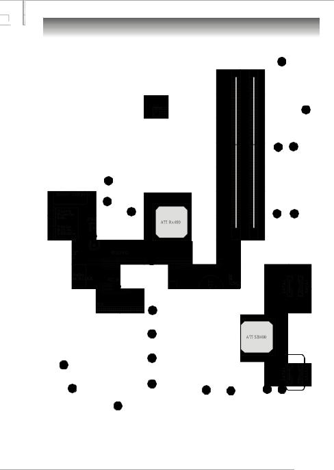
Mainboard Layout
7
12
1 3
2
4
4 |
5 |
5 |
2
8
15
14
15 |
6 |
16
16
16
9
6
10 |
16 |
13 |
11 |
11 |
13 |
||||
|
4 |
|
|
|
RX480 Neo2 (MS-7151 v1.X) ATX Mainboard
E-7
MS-7151 ATX Mainboard
1ATX 24-Pin Power Connector: JPWR1 This connector allows you to connectto an ATX power suply.
2ATX 12V Power Connector: JPWR2, JPWR3 This power connector is provided to connect 12V power suply.
3Floppy Disk Drive Connector: FDD1 This mainboard provides a standard floppy disk drive connector that supports 360K, 720K, 1.2M, 1.44M and 2.88M floppy disk types.
4Fan Power Connecors: CPU_FAN, NB_FAN, SYS_FAN These fan connectors support system cooling fan with +12V.
5ATA 133 Hard Disk Connectors: IDE1 & IDE2 This mainboard has a 32bit Enhanced PCI IDE and Ultra DMA 66/100/133 controller that provides PIO mode 0~4, Bus Master and Ultra DMA 66/100/133 function.
6Serial ATA/ Serial ATA Connectors controlled by ATI SB400: SATA1 / SATA2 / SATA3 / SATA4 The chipset of this mainboard is SB400 which supports four serial ATA connectors SATA1~SATA4. SATA1~SATA4 are high-speed Serial ATA interface ports. Each supports serial ATA data rate of 150 MB/s.
7Chassis Intrusion Switch Connector: JCI1 This connector is connected to a 2-pin chassis switch. If the chassis is opened, the switch will be short.
8CD-In Connector: JCD1 The connector is for CD-ROM audio connector.
9Front Panel Audio Connector: JAUD1 This front panel audio connector allows you to connect to the front panel audio.
10Serial Port Header: JCOM1 (Optional) The mainboard offers one 9-pin header as serial port to attach a serial mouse or other serial devices.
11Front Panel Connectors: JFP1, JFP2 The mainboard provides one front panel connector for electrical connection to the front panel switches and
LEDs.
Power |
Power |
|
|
|
|
LED |
Switch |
|
|
Speaker |
|
2 |
10 |
JFP1 |
JFP2 |
2 |
8 |
1 |
9 |
1 |
7 |
||
HDD |
Reset |
|
|
Power LED |
|
LED |
Switch |
|
|
|
|
|
|
|
|
E-8

User’s Manual
12IrDA Infrared Module Header: JIR1 The connector allows you to connect to IrDA Infrared module. You must configure the setting through the BIOS setup to use the IR function. JIR1 is compliant with Intel Front Panel I/O Connectivity Design Guide.
13Front USB Connectors: JUSB1, JUSB2 This mainboard provides two standard USB2.0 pin headers that allow you to connect USB devices via an external USB bracket.
14Clear CMOS Jumper: JCMOS1 There is a CMOS RAM onboard that has a power supply from external battery to keep the data of system configuration. With the CMOS RAM, the system can automatically boot OS every time it is turned on. If you want to clear the system configuration, set the JCMOS1 (Clear CMOS Jumper ) to clear data.
15PCI Express slots: PCIE16X1 , PCI_ E1 The PCI Express slots support high-bandwidth, low pin count, and serial interconnect technology. You can insert the expansion cards to meet your needs. When adding or removing expansion cards, make sure that you unplug the power supply first. PCI Express architecture provides a high performance I/O infrastructure for Desktop Platforms with transfer rates starting at 2.5 Giga transfers per second over a PCI Express x1 lane for Gigabit Ethernet, TV Tuners, 1394 controllers, and general purpose I/O. Also, desktop platforms with PCI Express Architecture will be designed to deliver highest performance in video, graphics, multimedia and other sophisticated applications. Moreover, PCI Express architecture provides a high performance graphics infrastructure for Desktop Platforms doubling the capability of existing AGP 8x designs with transfer rates of 4.0 GB/s over a PCI Express x16 lane for graphics controllers, while PCI Express x1 supports transfer rate of 250 MB/s.
16PCI Slots The PCI slots allow you to insert the expansion cards to meet your needs. When adding or removing expansion cards, make sure that you unplug the power supply first.
E-9
MS-7151 ATX Mainboard
Central Processing Unit: CPU
The mainboard supports AMD® Athlon64 processor. The mainboard uses a CPU socket called Socket-939 for easy CPU installation. When you are installing the CPU, make sure the CPU has a heat sink and a cooling fan attached on the top to prevent overheating. If you do not have the heat sink and cooling fan, contact your dealer to purchase and install them before turning on the computer.
For the latest information about CPU, please visit http://www.msi.com.tw/pro- gram/products/mainboard/mbd/pro_mbd_cpu_support.php.
MSI Reminds You...
Overheating
Overheating will seriously damage the CPU and system, always make sure the cooling fan can work properly to protect the CPU from overheating.
Replacing the CPU
While replacing the CPU, always turn off the ATX power supply or unplug the power supply’s power cord from grounded outlet first to ensure the safety of CPU.
E-10
User’s Manual
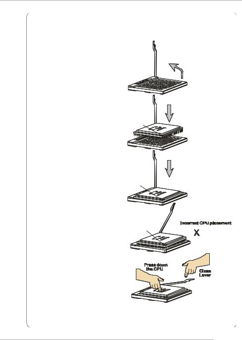
CPU Installation Procedures for Socket 939
1. Please turn off the power and |
|
|
unplug the power cord before |
|
Open Lever |
installing the CPU. |
|
|
|
Sliding |
90 degree |
|
Plate |
|
|
|
2.Pull the lever sideways away from the socket. Make sure to raise the lever up to a 90degree angle.
3.Look for the gold arrow of the CPU. The gold arrow should point as shown in the picture. The CPU can only fit in the correct orientation.
4.If the CPU is correctly installed, the pins should be completely embedded into the socket and can not be seen. Please note that any violation of the correct installation procedures may cause permanent damages to your mainboard.
5.Press the CPU down firmly into the socket and close the lever. As the CPU is likely to move while the lever is being closed, always close the lever with your fingers pressing tightly on top of the CPU to make sure the CPU is properly and completely embedded into the socket.
Gold arrow
Correct CPU placement
Gold arrow |
O |
|
Gold arrow
E-11

MS-7151 ATX Mainboard
Installing AMD Athlon64 CPU Cooler Set
When you are installing the CPU, make sure the CPU has a heat sink and a cooling fan attached on the top to prevent overheating. If you do not have the heat sink and cooling fan, contact your dealer to purchase and install them before turning on the computer.
MSI Reminds You...
Mainboard photos shown in this section are for demonstration of the cooler installation for Socket 939 CPUs only. The appearance of your mainboard may vary depending on the model you purchase.
1.Position the cooling set onto the retention mechanism.
Hook one end of the clip to hook first, and then press down the other end of the clip to fasten the cooling set on the top of the retention mechanism.
2.Locate the Fix Lever, Safety Hook and the Fixed Bolt.
Lift up the intensive fixed lever.
3. Fasten down the lever.
4.Make sure the safety hook completely clasps the fixed bolt of the retention mechanism.
Safety Hook |
5. Attach the CPU Fan cable to the CPU |
|
fan connector on the mainboard. |
||
|
Fixed Lever |
Fixed Bolt |
E-12
User’s Manual
Memory
The mainboard provides 2 slots for 184-pin DDR DIMM (Double In-Line Memory Module) modules and supports the memory size up to 2GB. You can install DDR 333/ 400 modules on the DDR DIMM slots (DIMM 1~2).
DIMM1~DIMM2 (from right to left)
DIMM Module Combination
Install at least one DIMM module on the slots. Each DIMM slot supports up to a maximum size of 1GB. Users can install either singleor double-sided modules to meet their own needs. Users may install memory modules of different type and density on different-channel DDR DIMMs. However, memory modules of the same type and density are required while using dual-channel DDR, or instability may happen.
Slots |
|
|
DIMM1 (CH A) |
DIMM2 (CH B) |
Mode |
128MB~1GB |
|
Single Channel |
128MB~1GB |
128MB~1GB |
Dual Channel |
MSI Reminds You...
-The system operates ONLY when the DDR modules are installed in accordance with the above-mentioned memory population rules.
-In dual-channel mode, make sure that you install memory modules of the same type and density on DDR DIMMs.
-To enable successful system boot-up, always insert the memory modules into the Channel A slots (DIMM1) first.
-This mainboard DO NOT support the memory module installed with more than 18 pieces of IC (integrated circuit).
E-13
MS-7151 ATX Mainboard
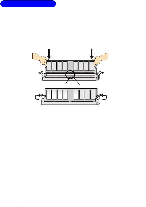
Installing DDR Modules
1.The DDR DIMM has only one notch on the center of module. The module will only fit in the right orientation.
2.Insert the DIMM memory module vertically into the DIMM slot. Then push it in until the golden finger on the memory module is deeply inserted in the socket.
3.The plastic clip at each side of the DIMM slot will automatically close.
Volt Notch
E-14
User’s Manual
BIOS Setup
Power on the computer and the system will start POST (Power On Self Test) process. When the message below appears on the screen, press <DEL> key to enter Setup.
Press DEL to enter SETUP
If the message disappears before you respond and you still wish to enter Setup, restart the system by turning it OFF and On or pressing the RESET button. You may also restart the system by simultaneously pressing <Ctrl>, <Alt>, and <Delete> keys.
Control Keys
<−> |
Move to the previous item |
|
|
<↓> |
Move to the next item |
|
|
<←> |
Move to the item in the left hand |
|
|
<→> |
Move to the item in the right hand |
|
|
<Enter> |
Select the item |
|
|
<Esc> |
Jumps to the Exit menu or returns to the main menu from a submenu |
|
|
<+/PU> |
Increase the numeric value or make changes |
|
|
<-/PD> |
Decrease the numeric value or make changes |
|
|
<F1> |
General help, only for Status Page Setup Menu and Option Page |
|
Setup Menu |
|
|
<F5> |
Restore the previous CMOS value from CMOS, only for Option Page |
|
Setup Menu |
|
|
<F6> |
Load the default CMOS value from Fail-Safe default table, only for |
|
Option Page Setup Menu |
<F7> |
Load Optimized defaults |
<F10> |
Save all the CMOS changes and exit |
|
|
Getting Help
After entering the Setup menu, the first menu you will see is the Main Menu.
Main Menu
The main menu lists the setup functions you can make changes to. You can use the control keys ( −↓ ) to select the item. The on-line description of the highlighted setup function is displayed at the bottom of the screen.
Sub-M enu
If you find a right pointer symbol (as shown in the right view) appears to the left of certain fields that means a sub-menu containing additional options can be launched from this field. You can use control keys ( −↓ ) to highlight the field and press <Enter> to call up the submenu. Then you can use the control keys to enter val-
ues and move from field to field within a sub-menu. If you want to return to the main menu, just press <Esc >.
General Help <F1>
The BIOS setup program provides a General Help screen. You can call up this screen from any menu by simply pressing <F1>. The Help screen lists the appropriate keys to use and the possible selections for the highlighted item. Press <Esc> to exit the Help screen.
E-15

MS-7151 ATX Mainboard
The Main Menu
Once you enter AMIBIOS NEW SETUP UTILITY, the Main Menu will appear on the screen. Use arrow keys to move among the items and press <Enter> to enter the sub-menu.
Standard CMOS Features
Use this menu for basic system configurations, such as time, date etc.
Advanced BIOS Features
Use this menu to setup the items of AMI® special enhanced features.
Advanced Chipset Features
Use this menu to change the values in the chipset registers and optimize your system’s performance.
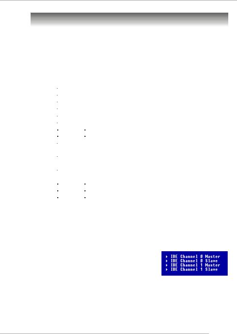
Integrated Peripherals
Use this menu to specify your settings for integrated peripherals.
Power Management Features
Use this menu to specify your settings for power management.
PNP/PCI Configurations
This entry appears if your system supports PnP/PCI.
H/W Monitor
This entry shows the status of your CPU, fan, warning for overall system status.
E-16
 Loading...