


MS-7304 (V1.X) Mainboard
i

Copyright Notice
The material in this document is the intellectual property of M ICRO-STAR INTERNATIONAL. We take every care in the preparation of this document, but no guarantee is given as to the correctness of its contents. Our products are under continual improvement and we reserve the right to make changes without notice.
Trademarks
All trademarks are the properties of their respective owners.
Intel® and Pentium® are registered trademarks of Intel Corporation.
AMD, Athlon™, Athlon™ XP, Thoroughbred™, and Duron™ are registered trademarks of AMD Corporation.
NVIDIA, the NVIDIA logo, DualNet, and nForce are registered trademarks or trademarks of NVIDIA Corporation in the United States and/or other countries.
PS/2 and OS®/2 are registered trademarks of International Business Machines Corporation.
Windows® 95/98/2000/NT/XP are registered trademarks of Microsoft Corporation. Netware® is a registered trademark of Novell, Inc.
Award® is a registered trademark of Phoenix Technologies Ltd. AMI® is a registered trademark of American Megatrends Inc.
Revision History
Revision |
Revision History |
Date |
V1.0 |
First release |
February 2008 |
Technical Support
If a problem arises with your system and no solution can be obtained from the user’s manual, please contact your place of purchase or local distributor. Alternatively, please try the following help resources for further guidance.
 Visit the MSI website at http://global.msi.com.tw/index.php? func=faqIndex for FAQ, technical guide, BIOS updates, driver updates, and other information.
 Contact our technical staff at http://support.msi.com.tw/.
ii

Safety Instructions
1.Always read the safety instructions carefully.
2.Keep this User’s Manual for future reference.
3.Keep this equipment away from humidity.
4.Lay this equipment on a reliable flat surface before setting it up.
5.The openings on the enclosure are for air convection hence protects the equipment from overheating. DO NOT COVER THE OPENINGS.
6.Make sure the voltage of the power source and adjust properly 110/220V before connecting the equipment to the power inlet.
7.Place the power cord such a way that people can not step on it. Do not place anything over the power cord.
8.Always Unplug the Power Cord before inserting any add-on card or module.
9.All cautions and warnings on the equipment should be noted.
10.Never pour any liquid into the opening that could damage or cause electrical shock.
11.If any of the following situations arises, get the equipment checked by service personnel:
The power cord or plug is damaged. Liquid has penetrated into the equipment.
The equipment has been exposed to moisture.
The equipment does not work well or you can not get it work according to User’s Manual.
The equipment has dropped and damaged. The equipment has obvious sign of breakage.
12. DONOT LEAVETHIS EQUIPMENT INANENVIRONMENT UNCONDITIONED, STORAGE TEMPERATURE ABOVE 600 C (1400F), IT MAYDAMAGE THE EQUIPMENT.
CAUTION: Danger of explosion if battery is incorrectly replaced. Replace only with the same or equivalent type recommended by the manufacturer.
iii
FCC-B Radio Frequency Interference Statement
This equipment has been tested and found to comply with the limits for a Class B digital device, pursuant to Part
15 of the FCC Rules. These limits are designed to provide reasonable protection against harmful interference in a residential installation. This equipment generates, uses and can radiate radio frequency energy and, if not installed and used in accordance with the instructions, may cause harmful interference to radio communications. However, there is no guarantee that interference will not occur in a particular installation. If this equipment does cause harmful interference to radio or television reception, which can be determined by turning the equipment off and on, the user is encouraged to try to correct the interference by one or more of the measures listed below.
Reorient or relocate the receiving antenna.
Increase the separation between the equipment and receiver.
Connect the equipment into an outlet on a circuit different from that to which the receiver is connected.
Consult the dealer or an experienced radio/television technician for help.
Notice 1
The changes or modifications not expressly approved by the party responsible for compliance could void the user’s authority to operate the equipment.
Notice 2
Shielded interface cables and A.C. power cord, if any, must be used in order to comply with the emission limits.
VOIR LANOTICE D’INSTALLATIONAVANT DE RACCORDER AU RESEAU.
Micro-Star International
MS-7304
This device complies with Part 15 of the FCC Rules. Operation is subject to the following two conditions:
(1)this device may not cause harmful interference, and
(2)this device must accept any interference received, including interference that may cause undesired operation.
iv

WEEE (Waste Electrical and Electronic Equipment) Statement
v

vi

vii
|
CONTENTS |
|
Copyright |
Notice .............................................................................................................. |
ii |
Trademarks ....................................................................................................................... |
ii |
|
Revision |
History .............................................................................................................. |
ii |
Technical |
Support ........................................................................................................... |
ii |
Safety Instructions ......................................................................................................... |
iii |
|
FCC-B Radio Frequency Interference Statement ........................................................ |
iv |
|
WEEE (Waste Electrical and Electronic Equipment) Statement .................................... |
v |
|
Chapter 1 Getting Started ..................................................................................... |
1-1 |
|
Mainboard Specifications ................................................................................... |
1-2 |
|
Mainboard Layout ................................................................................................ |
1-4 |
|
Chapter 2 Hardware Setup .................................................................................... |
2-1 |
|
Quick Components Guide .................................................................................... |
2-2 |
|
CPU (Central Processing Unit) ............................................................................ |
2-3 |
|
Memory................................................................................................................. |
2-6 |
|
Power Supply ...................................................................................................... |
2-8 |
|
Back Panel ............................................................................................................ |
2-9 |
|
Connector ........................................................................................................... |
2-11 |
|
Slot ...................................................................................................................... |
|
2-16 |
Jumper ................................................................................................................ |
2-17 |
|
Chapter 3 BIOS Setup ............................................................................................. |
3-1 |
|
Entering Setup ..................................................................................................... |
3-2 |
|
The Main Menu ..................................................................................................... |
3-4 |
|
Standard CMOS Features ................................................................................... |
3-6 |
|
Advanced BIOS Features ................................................................................... |
3-8 |
|
Integrated Peripherals ........................................................................................ |
3-11 |
|
Power Management Setup ............................................................................... |
3-13 |
|
PNP/PCI Configurations ..................................................................................... |
3-15 |
|
H/W Monitor ........................................................................................................ |
3-17 |
|
Frequency/Voltage Control ............................................................................... |
3-18 |
|
Load Fail-Safe / Optimized Defaults ................................................................ |
3-21 |
|
Set Supervisor Password ................................................................................ |
3-22 |
|
viii
Getting Started
Chapter 1
Getting Started
Thank you for choosing the MS-7304 v1.X Micro-ATX mainboard. The MS-7304 is based on AMD® RS780 & SB700 chipsets for optimal system efficiency. Designed to fit the advanced AMD® Athlon64 / Athlon64 X2 / AM2+ processors in Socket AM2/ AM2+, the MS-7304 delivers a high performance and professional desktop platform solution.
1-1
MS-7304 Mainboard
Mainboard Specifications
 Processor
-Supports AMD Athlon64 / Athlon64 X2 /AM2+ processors
-Supports 4-pin CPU fan pinheader with Fan Speed Control
-Supports up to 5000+ and above
 FSB
FSB
- Hyper Transport supports up to 3.0GHz
 Chipset
-North Bridge: AMD RS780
-South Bridge: AMD SB700
 M emory
-DDR2 533/667/800/1066 SDRAM (240 pins / 1.8V)
-4 DDR2 DIMM slots (8GB Max)
 LAN
LAN
- Gigabit Fast Ethernet by Realtek RTL8111C
 IEEE 1394
-Chip integrated by JMicron 381
-Transfer rate is up to 400MB/s
 Audio
Audio
-Chip integrated by Realtek ALC888S
-Flexible 8-channel audio with jack sensing
-Compliant with Azalia 1.0 Spec
 SATA
SATA
-SATA II ports by SB700
-Supports 4 SATA II devices
-Supports storage and data transfers at up to 300MB/s
1-2
Getting Started
Connectors
 Back Panel
-1 SPDIF-out port
-1 DVI port
-1 IEEE 1394 port
-6 USB 2.0 ports
-1 Gigabit LAN jack
-6 flexible audio jacks
 Onboard Connectors
-2 USB 2.0 connectors (4 ports)
-1 IEEE 1394 connector
-1 SPDIF-out connector
-1 front panel connector
-1 front panel audio connector
Slots
-1 PCI Express x16 slot
-1 PCI Express x1 slot
-2 32-bit/33MHz PCI slots
Form Factor
- M-ATX (24.4cm X 24.4 cm)
Mounting
- 8 mounting holes
1-3

MS-7304 Mainboard
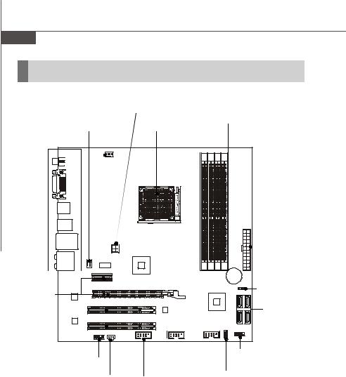
Mainboard Layout
JSPDO2 |
CPU_FAN1 |
|
|
|
|
|
|
|
|
|
|
|
|
|
|
|
|
DVI Port |
|
|
|
|
|
|
|
|
USB Ports |
|
|
|
|
|
|
|
|
Top: 1394 Port |
|
|
|
|
|
|
|
X1 |
|
|
|
|
|
|
|
AT |
|
Bottom: USB Ports |
|
|
|
|
|
|
||
|
|
|
|
|
|
|
||
Top: LAN Jack |
|
|
|
|
|
|
|
|
Bottom: USB Ports |
|
|
|
|
|
|
|
|
T: Line-In |
AUX_FAN1 |
JPW1 |
|
|
|
|
|
|
M: Line-Out |
|
|
|
|
|
|
||
B: Mic |
|
AMD |
|
|
|
|
|
|
T: RS-Out |
|
RS780 |
|
|
|
|
|
|
M: CS-Out |
PCI E1_X1 |
|
1 |
2 |
3 4 |
|
|
|
B: SS-Out |
|
|
|
|
||||
|
|
|
M |
M |
M M |
BATT |
|
|
|
|
|
IM |
IM |
IM IM |
|
||
|
|
|
|
+ |
|
|||
|
|
|
D |
D |
D D |
|
|
|
|
|
|
|
|
|
|||
|
PCI E16_X1 |
|
|
|
|
CLR_CMOS1 |
||
|
|
|
|
|
|
|
||
LAN Chip |
|
|
|
AMD |
|
2 |
4 |
|
|
|
|
|
|
ATA |
ATA |
||
|
PCI 2 |
|
|
SB700 |
|
|||
|
|
|
|
|
|
S |
S |
|
Audio C hip |
PCI 1 |
|
|
|
|
|
S ATA 3 |
S ATA 1 |
|
|
F_USB2 |
F_USB1 |
|
|
|
||
|
JAUD1 JSPDO1 |
|
|
|
|
|
|
|
|
|
J1394 |
|
|
JSPI1 |
JFP1 |
|
|
|
|
|
|
|
|
|||
MS-7304 (v1.X) Micro-ATX Mainboard
1-4
Hardware Setup
Chapter 2
Hardware Setup
This chapter provides you with the information about hardware setup procedures. While doing the installation, be careful in holding the components and follow the installation procedures. For some components, if you install in the wrong orientation, the components will not work properly.
Use a grounded wrist strap before handling computer components. Static elec tric ity may damage the components.
2-1
MS-7304 Mainboard
Quick Components Guide
|
JPW1, p.2-8 |
|
||
|
CPU _FAN 1, |
DIMM Slots, p.2-6 |
||
Back Panel |
AUX_FAN1, |
|||
CPU, p.2-3 |
|
|||
I/O, p.2-9 |
p.2-12 |
|
||
|
|
|
ATX1, p.2-8 |
|
|
|
|
BATT |
|
|
|
|
+ |
|
PCI Express |
|
|
CLR_CMOS1, |
|
|
|
p.2-16 |
||
Slots, p.2-17 |
|
|
|
|
|
|
|
SATA1~4, |
|
|
|
|
p.2-11 |
|
PCI Slots, |
|
|
|
|
p.2-17 |
|
|
|
|
|
|
F_USB1~2, |
JFP1, p.2-15 |
|
JAUD1, p.2-13 |
|
|||
p.2-14 |
|
|||
|
JSPDO1, p.2-12 |
JSPI1, p.2-11 |
||
|
J1394, p.2-14 |
|
||
2-2

Hardware Setup
CPU (Central Processing Unit)
The mainboard supports AMD® Athlon64 / Athlon64 X2 / AM2+ processors in Socket AM2/ AM2+. The Socket AM2/ AM2+ offers easy CPU installation. When you are installing the CPU, make sure the CPU has a heat sink and a cooling fan attached on the top to prevent overheating. If you do not have the heat sink and cooling fan, contact your dealer to purchase and install them before turning on the computer.
For the latest information about CPU, please visit http://global.msi.com.tw/index. php?func=cpuform.
Important
Overheating
Overheating will seriously damage the CPU and system. Always make sure the cooling fan can work properly to protect the CPU from overheating. Make sure that you apply an even layer of thermal paste (or thermal tape) between the CPU and the heatsink to enhance heat dissipation.
Replacing the CPU
While replacing the CPU, always turn off the power supply or unplug the power supply’s power cord from the grounded outlet first to ensure the safety of CPU.
2-3
MS-7304 Mainboard
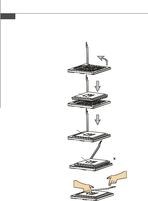
CPU Installation Procedures for Socket AM2/ AM2+
1.Please turn off the power and unplug the power cord before installing the CPU.
2.Pull the lever sideways away from the socket. Make sure that you raise the lever up to a 90degree angle.
|
Open the lever |
Sliding |
|
the plate |
90 degree |
3. Look for the gold arrow on the |
Gold arrow |
CPU. The gold arrow should point |
|
as shown in the picture. The CPU |
|
c an only f it i n the c orrec t |
|
orientation. Lower the CPU down |
|
onto the socket. |
|
4.If the CPU is correctly installed, the pins should be completely embedded into the socket and can not be seen. Please note that any violation of the correct installation proc edures may cause permanent damage to your mainboard.
5.Press the CPU down firmly into the socket and close the lever. As the CPU is likely to move while the lever is being closed, always close the lever with your fingers pressing tightly on top of the CPU to make sure the CPU is properly and completely embedded into the socket.
Gold arrow
Gold arrow
Press down the CPU
Correct CPU placement
O
Incorrect CPU placement
Close the lever
2-4
 Loading...