


MS-9232 1U Rackmount Server
G52-92321X1
i

Copyright Notice
The material in this document is the intellectual property of M ICRO-STAR INTERNATIONAL. We take every care in the preparation of this document, but no guarantee is given as to the correctness of its contents. Our products are under continual improvement and we reserve the right to make changes without notice.
Trademarks
All trademarks are the properties of their respective owners.
Intel® and Pentium® are registered trademarks of Intel Corporation.
AMD, Athlon™, Athlon™ XP, Thoroughbred™, and Duron™ are registered trademarks of AMD Corporation.
NVIDIA, the NVIDIA logo, DualNet, and nForce are registered trademarks or trademarks of NVIDIA Corporation in the United States and/or other countries.
PS/2 and OS®/2 are registered trademarks of International Business Machines Corporation.
Windows® 95/98/2000/NT/XP are registered trademarks of Microsoft Corporation. Netware® is a registered trademark of Novell, Inc.
Award® is a registered trademark of Phoenix Technologies Ltd. AMI® is a registered trademark of American Megatrends Inc.
Revision History
Revision |
Revision History |
Date |
V1.0 |
First release |
November 2006 |
Technical Support
If a problem arises with your system and no solution can be obtained from the user’s manual, please contact your place of purchase or local distributor. Alternatively, please try the following help resources for further guidance.
 Visit the MSI website at http://www.msi.com.tw/program/service/faq/ faq/esc_faq_list.php for FAQ, technical guide, BIOS updates, driver updates, and other information.
 Contact our technical staff at http://support.msi.com.tw/.
ii

Safety Instructions
1.Always read the safety instructions carefully.
2.Keep this User’s Manual for future reference.
3.Keep this equipment away from humidity.
4.Lay this equipment on a reliable flat surface before setting it up.
5.The openings on the enclosure are for air convection hence protects the equipment from overheating. DO NOT COVER THE OPENINGS.
6.Make sure the voltage of the power source and adjust properly 110/220V before connecting the equipment to the power inlet.
7.Place the power cord such a way that people can not step on it. Do not place anything over the power cord.
8.Always Unplug the Power Cord before inserting any add-on card or module.
9.All cautions and warnings on the equipment should be noted.
10.Never pour any liquid into the opening that could damage or cause electrical shock.
11.If any of the following situations arises, get the equipment checked by a service personnel:
†The power cord or plug is damaged.
†Liquid has penetrated into the equipment.
†The equipment has been exposed to moisture.
†The equipment has not work well or you can not get it work according to User’s Manual.
†The equipment has dropped and damaged.
†The equipment has obvious sign of breakage.
12.DONOT LEAVETHIS EQUIPMENT INANENVIRONMENT UNCONDITIONED, STORAGE TEMPERATURE ABOVE 600 C (1400F), IT MAYDAMAGE THE EQUIPMENT.
CAUTION: Danger of explosion if battery is incorrectly replaced. Replace only with the same or equivalent type recommended by the manufacturer.
iii

FCC-B Radio Frequency Interference Statement
This equipment has been tested and found to comply with the limits for a Class B digital device, pursuant to Part
15 of the FCC Rules. These limits are designed to provide reasonable protection against harmful interference in a residential installation. This equipment generates, uses and can radiate radio frequency energy and, if not installed and used in accordance with the instructions, may cause harmful interference to radio communications. However, there is no guarantee that interference will not occur in a particular installation. If this equipment does cause harmful interference to radio or television reception, which can be determined by turning the equipment off and on, the user is encouraged to try to correct the interference by one or more of the measures listed below.
†Reorient or relocate the receiving antenna.
†Increase the separation between the equipment and receiver.
†Connect the equipment into an outlet on a circuit different from that to which the receiver is connected.
†Consult the dealer or an experienced radio/television technician for help.
Notice 1
The changes or modifications not expressly approved by the party responsible for compliance could void the user’s authority to operate the equipment.
Notice 2
Shielded interface cables and A.C. power cord, if any, must be used in order to comply with the emission limits.
VOIR LANOTICE D’INSTALLATIONAVANT DE RACCORDER AU RESEAU.
Micro-Star International
MS-9232
This device complies with Part 15 of the FCC Rules. Operation is subject to the following two conditions:
(1)this device may not cause harmful interference, and
(2)this device must accept any interference received, including interference that may cause undesired operation.
iv

WEEE (Waste Electrical and Electronic Equipment) Statement
v

vi

vii
|
CONTENTS |
|
Copyright |
Notice ............................................................................................................. |
iii |
Trademarks ...................................................................................................................... |
iii |
|
Revision |
History ............................................................................................................. |
iii |
Technical |
Support .......................................................................................................... |
iii |
Safety Instructions ......................................................................................................... |
iii |
|
FCC-B Radio Frequency Interference Statement ......................................................... |
v |
|
WEEE (Waste Electrical and Electronic Equipment) Statement .................................... |
v |
|
Chapter 1 Getting Started ..................................................................................... |
1-1 |
|
System Overview ............................................................................................... |
1-2 |
|
Mainboard Specifications ................................................................................... |
1-6 |
|
Mainboard Layout ................................................................................................ |
1-8 |
|
MSI Special Feature ............................................................................................ |
1-8 |
|
Core Center (Optional) ................................................................................ |
1-9 |
|
Chapter 2 Hardware Setup .................................................................................... |
2-1 |
|
Quick Components Guide .................................................................................... |
2-2 |
|
CPU (Central Processing Unit) ............................................................................ |
2-3 |
|
Memory................................................................................................................. |
2-4 |
|
Memory Population Rules ............................................................................ |
2-5 |
|
Installing DDRII Modules ............................................................................... |
2-5 |
|
Power Supply ...................................................................................................... |
2-6 |
|
SSI 24-Pin System Power Connector: ATX1 ............................................. |
2-7 |
|
SSI 4-Pin CPU Power Connector: JPW1, JPW2 ........................................ |
2-7 |
|
Floppy Disk Drive Connector: FDD1 ............................................................ |
2-7 |
|
ATA100 Hard Disk Connector: IDE1 ............................................................ |
2-7 |
|
Connectors .......................................................................................................... |
2-7 |
|
Serial ATA Connectors: SATA1~4 .............................................................. |
2-9 |
|
Front Panel Connectors: JFP1 .................................................................... |
2-9 |
|
Fan Power Connectors: CPUFAN1, SYSFAN1, SYSFAN2 ...................... |
2-9 |
|
Chassis Intrusion Switch Connector: JCI2 .............................................. |
2-10 |
|
FWH/LPC Debugging Pin Header: JLPC1 ................................................. |
2-10 |
|
Serial Port Connector: COM1 .................................................................... |
2-10 |
|
Jumpers .............................................................................................................. |
2-10 |
|
Clear CMOS Jumper: CLR_CMOS1 ........................................................... |
2-11 |
|
BIOS Flash Jumper: BIOS_WP1 ................................................................. |
2-11 |
|
PCI (Peripheral Component Interconnect) Express Slot ......................... |
2-12 |
|
PCI (Peripheral Component Interconnect) Slot ........................................ |
2-12 |
|
System Assembly Flowchart ........................................................................... |
2-12 |
|
Slots |
.................................................................................................................... |
2-13 |
viii
System Assembly.............................................................................................. |
2-14 |
|
Removing the Chassis Cover ................................................................... |
2-15 |
|
Replacing the Chassis Cover .................................................................... |
2-16 |
|
CPU & Cooler Set Installation .................................................................... |
2-17 |
|
DDR-II Memory............................................................................................ |
2-19 |
|
PCI Expansion Card ................................................................................... |
2-20 |
|
Hard Disk Drives ........................................................................................ |
2-22 |
|
Rock Mounting ................................................................................................... |
2-24 |
|
Chassis |
Ears ............................................................................................. |
2-25 |
Chassis |
Rails ............................................................................................. |
2-25 |
Chassis into/off the Rack .......................................................................... |
2-27 |
|
Chapter 3 BIOS Setup ............................................................................................. |
3-1 |
|
Entering Setup ..................................................................................................... |
3-2 |
|
The Menu Bar ....................................................................................................... |
3-4 |
|
Main ...................................................................................................................... |
|
3-4 |
Advanced ............................................................................................................ |
|
3-6 |
PC Health ............................................................................................................ |
|
3-12 |
Security .............................................................................................................. |
|
3-12 |
System ............................................................................................................... |
|
3-14 |
Boot .................................................................................................................... |
|
3-14 |
Exit ...................................................................................................................... |
|
3-16 |
Appendix A Intel ICH7R SATA RAID ..................................................................... |
A-1 |
|
ICH7R Introduction ............................................................................................... |
A-2 |
|
BIOS Configuration .............................................................................................. |
A-2 |
|
Using the Intel Matrix Stroage Manager Option ROM ............................... |
A-3 |
|
Installing Software .............................................................................................. |
A-8 |
|
Install Driver in Windows XP / 2000 ........................................................... |
A-9 |
|
Installation of Intel Matrix Storage Console ............................................. |
A-11 |
|
RAID Migration Instructions ............................................................................... |
A-14 |
|
Create RAID Volume from Existing Disk ................................................... |
A-17 |
|
Degraded RAID Array ........................................................................................ |
A-22 |
|
Missing Hard Drive Member ...................................................................... |
A-23 |
|
Failed Hard Drive Member ......................................................................... |
A-23 |
|
ix
x
Getting Started
Chapter 1
Getting Started
The MS-9232 1U Rackmount Server is a high-perfor- mance barebone system powered by Intel® Core Duo/ Core Solo/Celeron M processor, Intel® 945GT, and
Intel® ICH7R chipsets. With high scalability, reliability, ease of use, and overall value, the MS-9232 makes an ideal choice for value conscious customers.
1-1
 MS-9232 Server
System Overview
This section shows the configuration of the MS-9232 from different angles, and the connectors and buttons on the front and back panel.
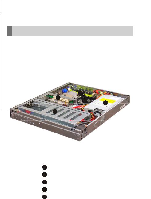
Top View
Front
4
2
3 5
1
Back
1HDD Tray
2PCI Riser Card Bracket
3CPU Socket
4Memory DIMM Slots
5EPS 1U Power Supply
1-2
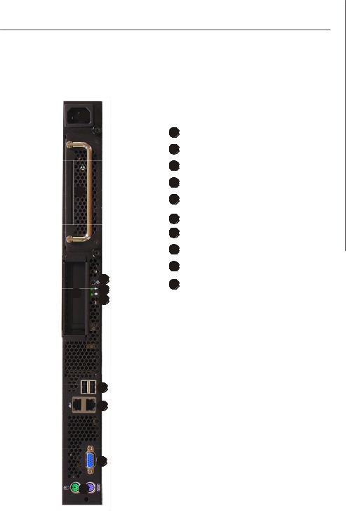
Front View
3
2
10
19
8
6
7
5
4
Getting Started
1PCI Card Bracket
2HDD Tray
3AC Power Connector
4PS/2 Mouse/Keyboard
5VGA Port
6USB Ports
7Gigabit LAN Jacks
8HDD LED
9Power LED
10 Power Button
1-3
 MS-9232 Server
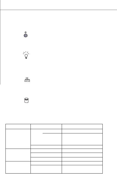
Power Button
This main power button is used to turn on or off the system.
Power LED
This indicator shows the power status of the system. It glows when the main power is turned on.
LAN Status Indicators
These LED indicators flash to show the activity status on LAN1 and LAN2.
HDD LED
This indicator shows the activity status of the hard disk drive. It flashes when the system is accessing data on the hard disk.
vFront I/O LEDs
LED |
Color |
State |
Description |
Power/Sleep |
Green |
On |
Legacy power on/ACPI S0 state |
|
|
Blink (~1/sec) |
Sleep/ACPI S1 state |
|
Off |
Off |
Power off/ACPI S4, S5 state |
HDD Activity |
Amber |
Random blink |
HDD accesss activity |
|
Off |
Off |
No disk activity |
RJ45 NIC 1 Linkage |
Green |
On |
LAN linked |
/RJ45 NIC 2 Linkage |
Green |
Blinking |
LAN accessing |
/RJ45 NIC 3 Linkage |
Off |
Off |
No LAN linked |
RJ45 NIC 1 Access |
Amber |
On |
Gigabit mode access |
/RJ45 NIC 2 Access |
Green |
On |
100M mode access |
/RJ45 NIC 3 Access |
Off |
Off |
10M mode access |
1-4
Getting Started
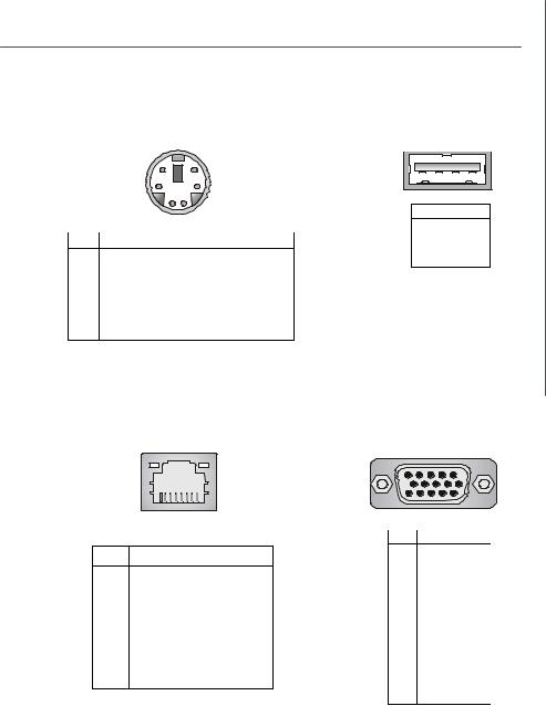
Mouse/Keyboard Connector |
USB Port |
|
|
|
||
|
|
|
1 |
2 |
3 |
4 |
|
6 |
5 |
|
|
|
|
|
4 |
3 |
|
|
|
|
|
2 |
1 |
PIN |
SIGNAL |
||
|
1 |
|
VCC |
|
||
|
|
|
|
|
||
PIN |
SIGNAL |
DESCRIPTION |
2 |
|
-Data |
|
3 |
|
+Data |
|
|||
1 |
Mouse/Keyboard Data |
Mouse/Keyboard data |
|
|
||
4 |
|
GND |
|
|||
2 |
NC |
Noconnection |
|
|
|
|
3 |
GND |
Ground |
|
|
|
|
4 |
VCC |
+5V |
|
|
|
|
5 |
Mouse/KeyboardClock |
Mouse/Keyboardclock |
|
|
|
|
6 |
NC |
Noconnection |
|
|
|
|
LAN Jack |
|
|
VGA Port |
|
|
|
|
|
5 |
1 |
|
|
8 |
1 |
15 |
11 |
|
Gigabit LAN Pin Definition |
PIN |
SIGNAL |
|||
PIN |
SIGNAL |
DESCRIPTION |
1 |
RED |
|
2 |
GREEN |
||||
|
|
|
|||
1 |
D0P |
Differential Pair 0+ |
3 |
BLUE |
|
2 |
D0N |
Differential Pair 0- |
4 |
N/C |
|
5 |
GND |
||||
3 |
D1P |
Differential Pair 1+ |
|||
6 |
GND |
||||
4 |
D2P |
Differential Pair 2+ |
7 |
GND |
|
8 |
GND |
||||
5 |
D2N |
Differential Pair 2- |
|||
9 |
+5V |
||||
6 |
D1N |
Differential Pair 1- |
10 |
GND |
|
11 |
N/C |
||||
7 |
D3P |
Differential Pair 3+ |
|||
12 |
SDA |
||||
8 |
D3N |
Differential Pair 3- |
13 |
Horizontal Sync |
|
14 |
Vertical Sync |
||||
|
|
|
|||
|
|
|
15 |
SCL |
|
1-5
 MS-9232 Server
Mainboard Specifications
 Processor Support
-Intel® Core Duo/Core Solo/Celeron M CPU in the 478 package
-Supports 3/4 pin CPU Fan Pin-Header with Fan Speed Control
-Supports Intel Dual Core Technology to 533/667MHz and up
Supported FSB
- 533/667MHz
 Chipset
-North Bridge: Intel® 945GT chipset
-South Bridge: Intel® ICH7R chipset
 Memory Support
-DDRII 533/667 SDRAM (4GB Max)
-2 DIMMs DDRII (240pin / 1.8V)
 LAN
LAN
- Supports PCI Express LAN GB Fast Ethernet by Intel 82573L
 IDE
IDE
-1 IDE port by ICH7R
-Supports Ultra DMA 66/100 mode
-Supports PIO, Bus Master operation mode
 SATA
SATA
-SATA II ports by ICH7R
-Supports four SATA II devices
-Supports storage and data transfers at up to 300MB/s
 RAID
RAID
- SATA1~4 supports RAID 0/ 1/ 0+1/ 5
 Floppy
-1 floppy port
-Supports 1 FDD with 360K, 720K, 1.2M, 1.44M and 2.88Mbytes
 Connectors
I/O Panel
-1 PS/2 mouse port
-1 PS/2 keyboard port
-2 x RJ45 Gigabit LAN
1-6
Getting Started
-2 USB 2.0 Ports
-1 VGA connector
Onboard Pinheaders
- 1 serial header (COM1)
Slots
-1 PCI Express x16 slot
-1 32-bit/33MHz PCI slot
 Chassis
-Form Factor: 1U
-Low profile slot x 1
-Chassis Dimension: 432mm (W) X 355mm (L) X 42.5mm (H)
Power Supply
-Input: 90-135/180-265Vac, Auto-Range
-Output: Maximum Power 200 Watts
For more information on compatible components, please visit http://www.msi.com.tw/program/products/server/svr/pro_svr_qvl.php
1-7
MS-9232 Server |
|
|
|
|
|
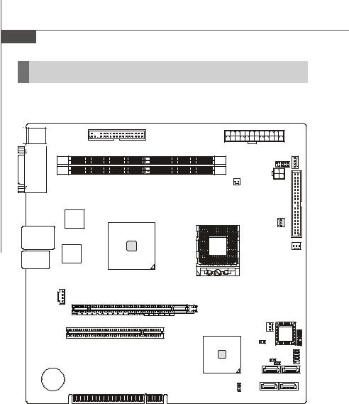
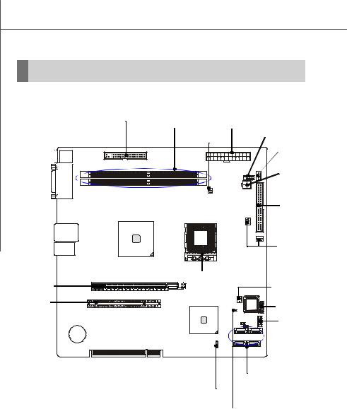
Mainboard Layout |
|
|
|
||
Top: Mouse |
|
|
|
|
|
Bottom: Keyboard |
FDD 1 |
|
ATX1 |
|
|
|
|
|
|
||
|
|
|
JPW2 |
||
|
|
|
|
||
|
|
|
DIMM1 |
COM1 |
|
|
|
|
|
|
|
VGA Port |
|
|
DIMM 2 |
|
|
|
|
|
|
|
|
|
|
|
JCI2 |
JPW1 |
|
|
|
|
|
|
|
|
|
|
|
IDE1 |
|
Intel |
|
|
|
1 |
|
|
|
|
FAN |
|
|
82573L |
|
|
|
|
|
|
|
|
|
|
|
|
|
Intel |
|
CPU |
|
LAN Jacks |
|
945GT |
|
|
|
|
|
|
|
|
|
Intel |
|
|
|
|
N2 |
82573L |
|
|
|
|
|
USB Ports |
|
|
|
|
SYSFA |
JCD1 |
|
|
|
|
|
|
|
|
|
|
|
PCI-E1 |
|
|
|
|
|
|
|
|
|
|
1 |
PCI3 |
|
|
|
SYSFAN1 |
JLPC |
|
|
|
|
||
|
|
|
|
|
|
|
|
BIOS |
|
Intel |
|
|
|
ICH7R |
BIOS WP1 |
|
|
|
|
J12 |
JFP1 |
|
|
|
|
|
|
J13 |
|
BATT |
|
SATA4 |
SATA3 |
+ |
|
|
|
CLR_CMOS1 |
SATA2 |
SATA1 |
|
|
|
||
945GT Speedster u-ATX Workstation Board (MS-9632 v1.X)
1-8

Getting Started
MSI Special Feature
Core Center (Optional)
The Core Center is a new utility you can find in the application CD. The utility is just like your PC doctor that can detect, view and adjust the PC hardware and system status during real time operation. In the left side it shows the current system status, including the Vcore, 3.3V, +5V and 12V. In the right side it shows the current PC hardware status such as the CPU & system temperatures and all fans speeds.
When you click the red triangles in the left and right sides, two sub-menus will open for users to overclock, overspec or to adjust the thresholds of system to send out the warning messages. If you click the Core Center button on the top, a screen pops up for you to choose the “Auto mode” or “User mode” of CPU fan. You may adjust the speeds of CPU fans and system fan here.
1-9

 MS-9232 Server
Left-side: Current system status
In the left sub-menu, you can configure the settings of FSB & DOT by clicking the radio button in front of each item and make it available (the radio button will be lit as yellow when selected), use the “+” and “-” buttons to adjust, then click “ok” to apply the changes. Then you can click Save to save the desired FSB you just configured.
Also you may click Auto to start testing the maximal CPU overclocking value. The CPU FSB will automatically increase the testing value until the PC reboots. Or you may click Default to restore the default values.
Right-side: PC hardware status during real time operation
In the right sub-menu, here you can configure the PC hardware status such as CPU & system temperatures and fan speeds. You may use the scroll bars to adjust each item, then click “ok” to apply the changes. The values you set for the temperatures are the maximum thresholds for the system for warnings, and the value for fan speeds are the minimum thresholds.
Top-side: User mode/Auto mode
Here you may adjust the CPU fan speed. If you choose User mode, you may adjust the CPU fan speed in 8 different modes, from Stop to Full speed.
Important
Items shown on Core Center may vary depending on your system status.
1-10
Hardware Setup
Chapter 2
Hardware Setup
|
Refer to the system assembly flowchart and the chart |
|
|
below to determine the proper sequence of removing |
|
|
or installing components to the server. |
|
|
Mainboard Hardware |
CPU, Memory, Power Supply, Back |
|
|
Panel, Connectors, Jumpers, Slot |
|
|
Chassis Cover |
|
|
CPU, Heatsink |
|
System Assembly |
Memory |
|
|
Riser Card |
MS-9232 |
|
Hard Disk Drives |
|
|
|
|
|
Chassis Ears and Rails |
|
Rack Mounting |
Rack Rails |
|
|
Chassis into the Rack |
|
|
Chassis off the Rack |
|
|
|
2-1
 MS-9232 Server
Quick Components Guide
FDD1, p.2-7 |
DDRII DIMMs, |
ATX1, |
|
p.2-4 |
p.2-10 |
JCI2, |
COM1,p.2-10 |
p.2-10 |
|
JPW2, p.2-6
|
|
JPW1, |
|
|
p.2-10 |
I/O Panel |
|
|
|
|
IDE1, |
|
|
p.2-7 |
|
|
CPUFAN1/ |
|
|
SYSFAN2, |
|
|
p.2-9 |
|
|
CPU, p.2-3 |
PCI-E Slot, |
|
SYSFAN1, |
p.2-12 |
|
p.2-9 |
PCI Slots, |
BIOS |
JLPC1, |
p.2-12 |
|
|
|
p.2-10 |
|
|
|
|
|
|
JFP1, |
|
|
p.2-9 |
SATA1~SATA4, p.2-8
CLR_CMOS1, p.2-11
BIOS_WP1, p.2-11
2-2

Hardware Setup
CPU (Central Processing Unit)
The mainboard supports Intel® Core Duo/Core Solo/Celeron M processors in 478-pin package. The mainboard uses Socket 478 for easy CPU installation. When you are installing the CPU, make sure the CPU has a heat sink and a cooling fan attached on the top to prevent overheating. If you do not have the heat sink and cooling fan, contact your dealer to purchase and install them before turning on the computer.
For more information on compatible components, please visit http://www.msi.com. tw/program/products/server/svr/pro_svr_qvl.php .
Important
1.Overheating will seriously damage the CPU and system. Always make sure the cooling fan can work properly to protect the CPU from overheating.
2.Make sure that you apply an even layer of heat sink paste (or thermal tape) between the CPU and the heatsink to enhance heat dissipation.
3.While replacing the CPU, always turn off the ATX power supply or unplug the power supply’s power cord from the grounded outlet first to ensure the safety of CPU.
2-3
 MS-9232 Server
Memory
The mainboard provides two 240-pin non-ECC DDRII 533/667 DIMMs and supports up to 4GB system memory.
For more information on compatible components, please visit http://www.msi.com. tw/program/products/server/svr/pro_svr_qvl.php.
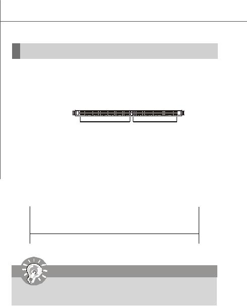
DDRII
240-pin, 1.8V
64x2=128 pin |
56x2=112 pin |
Single-Channel: All DIMMs in GREEN
Memory Population Rules
This mainboard supports DDRII 533/667 memory interface.
Each DIMM slot supports up to a maximum size of 2GB. Users can install either singleor double-sided modules depending on their needs.
Slot |
Combination 1 |
Combination 2 |
Combination 3 |
DIMM1 |
128MB~2GB |
0 |
128MB~2GB |
DIMM2 |
0 |
128MB~2GB |
128MB~2GB |
Total Memory |
128MB~2GB |
128MB~2GB |
256MB~4GB |
Important
Make sure that you install memory modules of the same type and density on DDRII DIMMs.
2-4
Hardware Setup
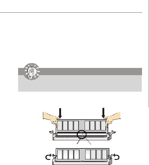
Installing DDRII Modules
1.The memory module has only one notch on the center and will only fit in the right orientation.
2.Insert the DIMM memory module vertically into the DIMM slot. Then push it in until the golden finger on the memory module is deeply inserted in the socket.
Important
You can barely see the golden finger if the module is properly inserted in the socket.
3. The plastic clip at each side of the DIMM slot will automatically close.
Volt Notch
2-5
|
ATX1 |
|
|
JPW1 |
|
JPW2 |
|||||
1 |
|
|
12 |
4 |
2 |
|
1 |
|
|
|
|
|
|
|
|
|
|
||||||
|
|
|
|
|
|
||||||
13 |
|
|
24 |
3 |
1 |
|
4 |
|
|
|
|
|
ATX1 Pin Definition |
|
|
|
|
|
|
|
|||
|
|
|
|
|
|
|
|
||||
|
|
|
|
|
|
|
|
|
|||
PIN |
SIGNAL |
PIN |
SIGNAL |
JPW1 Pin Definition |
JPW2 Pin Definition |
||||||
1 |
+3.3V |
13 |
+3.3V |
||||||||
|
|
PIN |
|
SIGNAL |
|||||||
2 |
+3.3V |
14 |
-12V |
PIN |
SIGNAL |
|
|||||
3 |
GND |
15 |
GND |
1 |
GND |
1 |
|
NA |
|||
4 |
+5V |
16 |
PS-ON# |
2 |
|
GND |
|||||
2 |
GND |
|
|||||||||
5 |
GND |
17 |
GND |
3 |
|
GND |
|||||
3 |
12V |
|
|||||||||
6 |
+5V |
18 |
GND |
4 |
|
12VIN |
|||||
4 |
12V |
|
|||||||||
7 |
GND |
19 |
GND |
|
|
|
|
|
|||
|
|
|
|
|
|
|
|||||
8 |
PWROK |
20 |
Res |
|
|
|
|
|
|
|
|
9 |
5VSB |
21 |
+5V |
|
|
|
|
|
|
|
|
10 |
+12V |
22 |
+5V |
|
|
|
|
|
|
|
|
11 |
+12V |
23 |
+5V |
|
|
|
|
|
|
|
|
12 |
NC |
24 |
GND |
|
|
|
|
|
|
|
|
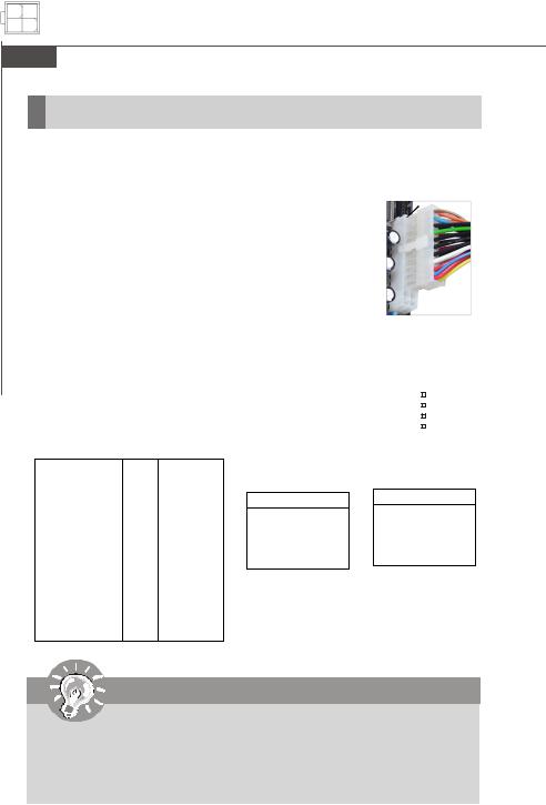
Important
1.Maker sure that these two connectors are connected to adequate SSI power supplies to ensure stable operation of the mainboard.
2.Power supply of 200watts (and above) is highly recommended for system stability.
3.SSI 12V power connection should be greater than 18A.
2-6
Hardware Setup
Connectors
Floppy Disk Drive Connector: FDD1
This standard FDD connector supports 360K, 720K, 1.2M, 1.44M and 2.88M floppy disk types.
FDD1
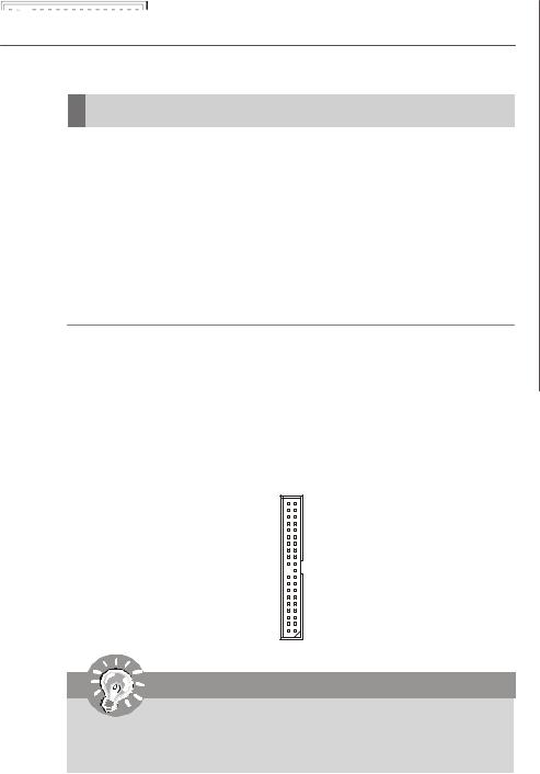
ATA100 Hard Disk Connector: IDE1
The mainboard has a 32-bit Enhanced PCI IDE and Ultra DMA 66/100 controller that provides PIO mode 0~4, Bus Master, and Ultra DMA 66/100 function. You can connect hard disk drives, CD-ROM and other IDE devices.
The Ultra ATA100 interface boosts data transfer rates between the computer and the hard drive up to 100 megabytes (MB) per second. The new interface is one-third faster than earlier record-breaking Ultra ATA 100 technology and is backwards compatible with the existing Ultra ATA interface.
IDE1
Important
If you install two hard disks on cable, you must configure the second drive to Slave mode by setting its jumper. Refer to the hard disk documentation supplied by hard disk vendors for jumper setting instructions.
2-7
 Loading...