

870A Fuzion
Power Edition series
MS-7660 (v1.x) Mainboard
G52-76601X7
Preface
MS-7660
Preface
Copyright Notice
The material in this document is the intellectual property of MICRO-STAR INTERNATIONAL. We take every care in the preparation of this document, but no guarantee is
given as to the correctness of its contents. Our products are under continual improvement and we reserve the right to make changes without notice.
Trademarks
All trademarks are the properties of their respective owners.
MSI® is registered trademark of Micro-Star Int’l Co.,Ltd.
■
NVIDIA® is registered trademark of NVIDIA Corporation.
■
ATI® is registered trademark of ATI Technologies, Inc.
■
AMD® is registered trademarks of AMD Corporation.
■
Intel® is registered trademarks of Intel Corporation.
■
Windows® is registered trademarks of Microsoft Corporation.
■
AMI® is registered trademark of American Megatrends, Inc.
■
Award® is a registered trademark of Phoenix Technologies Ltd.
■
Sound Blaster® is registered trademark of Creative Technology Ltd.
■
Realtek® is registered trademark of Realtek Semiconductor Corporation.
■
JMicron® is registered trademark of JMicron Technology Corporation.
■
Netware® is a registered trademark of Novell, Inc.
■
Lucid® is trademarks of LucidLogix Technologies, Ltd.
■
Revision History
Revision Revision History Date
V1.0 Release for PCB 1.X (Europe version) July 2010
Technical Support
If a problem arises with your system and no solution can be obtained from the user’s
manual, please contact your place of purchase or local distributor. Alternatively, please
try the following help resources for further guidance.
Visit the MSI website for FAQ, technical guide, BIOS updates, driver updates,
◙
and other information:
Contact our technical sta at:
◙
http://www.msi.com/index.php?func=service
http://ocss.msi.com
ii
MS-7660
Preface
Safety Instructions
Always read the safety instructions carefully.
■
Keep this User’s Manual for future reference.
■
Keep this equipment away from humidity.
■
Lay this equipment on a reliable at surface before setting it up.
■
The openings on the enclosure are for air convection hence protects the equipment
■
from overheating. DO NOT COVER THE OPENINGS.
Make sure the voltage of the power source and adjust properly 110/220V before
■
connecting the equipment to the power inlet.
Place the power cord such a way that people can not step on it. Do not place any-
■
thing over the power cord.
Always Unplug the Power Cord before inserting any add-on card or module.
■
All cautions and warnings on the equipment should be noted.
■
Never pour any liquid into the opening that could damage or cause electrical
■
shock.
If any of the following situations arises, get the equipment checked by service
■
personnel:
The power cord or plug is damaged.
◯
Liquid has penetrated into the equipment.
◯
The equipment has been exposed to moisture.
◯
The equipment does not work well or you can not get it work according to User’s
◯
Manual.
The equipment has dropped and damaged.
◯
The equipment has obvious sign of breakage.
◯
DO NOT LEAVE THIS EQUIPMENT IN AN ENVIRONMENT UNCONDITIONED,
STORAGE TEMPERATURE ABOVE 60oC (140oF), IT MAY DAMAGE THE EQUIPMENT.
MS-7660
Preface
CAUTION: Danger of explosion if battery is incorrectly replaced.
Replace only with the same or equivalent type recommended by the manufacturer.
警告使用者:
這是甲類資訊產品,在居住的環境中使用時,可能會造成無線電干擾,在這種情況下,
使用者會被要求採取某些適當的對策。
廢電池請回收
For better environmental protection, waste batteries should be
collected separately for recycling special disposal.
iii
Preface
MS-7660
Preface
FCC-B Radio Frequency Interference Statement
This equipment has been tested and found
to comply with the limits for a Class B digital device, pursuant to Part 15 of the FCC
Rules. These limits are designed to provide
reasonable protection against harmful interference in a residential installation. This equipment generates, uses and can radiate
radio frequency energy and, if not installed and used in accordance with the instructions, may cause harmful interference to radio communications. However, there is no
guarantee that interference will not occur in a particular installation. If this equipment
does cause harmful interference to radio or television reception, which can be determined by turning the equipment o and on, the user is encouraged to try to correct the
interference by one or more of the measures listed below.
Reorient or relocate the receiving antenna.
◯
Increase the separation between the equipment and receiver.
◯
Connect the equipment into an outlet on a circuit dierent from that to which the
◯
receiver is connected.
Consult the dealer or an experienced radio/television technician for help.
◯
Notice 1
The changes or modications not expressly approved by the party responsible for com-
pliance could void the user’s authority to operate the equipment.
Notice 2
Shielded interface cables and A.C. power cord, if any, must be used in order to comply
with the emission limits.
VOIR LA NOTICE D’INSTALLATION AVANT DE RACCORDER AU RESEAU.
Micro-Star International
MS-7660
This device complies with Part 15 of the FCC Rules. Operation is subject to the following two conditions:
this device may not cause harmful interference, and
1)
this device must accept any interference received, including interference that may
2)
cause undesired operation.
iv
MS-7660
Preface
MS-7660
WEEE (Waste Electrical and Electronic Equipment) Statement
ENGLISH
To protect the global environment and as an environmentalist, MSI must
remind you that...
Under the European Union (“EU”) Directive on Waste Electrical and Electronic Equipment, Directive 2002/96/EC, which takes eect on August 13,
2005, products of “electrical and electronic equipment” cannot be discarded
as municipal waste anymore and manufacturers of covered electronic equipment will be obligated to take back such products at the end of their useful life. MSI will
comply with the product take back requirements at the end of life of MSI-branded products that are sold into the EU. You can return these products to local collection points.
DEUTSCH
Hinweis von MSI zur Erhaltung und Schutz unserer Umwelt
Gemäß der Richtlinie 2002/96/EG über Elektro- und Elektronik-Altgeräte dürfen Elek-
tro- und Elektronik-Altgeräte nicht mehr als kommunale Abfälle entsorgt werden. MSI
hat europaweit verschiedene Sammel- und Recyclingunternehmen beauftragt, die in
die Europäische Union in Verkehr gebrachten Produkte, am Ende seines Lebenszyklus
zurückzunehmen. Bitte entsorgen Sie dieses Produkt zum gegebenen Zeitpunkt ausschliesslich an einer lokalen Altgerätesammelstelle in Ihrer Nähe.
FRANÇAIS
En tant qu’écologiste et an de protéger l’environnement, MSI tient à rappeler ceci...
Au sujet de la directive européenne (EU) relative aux déchets des équipement élec-
triques et électroniques, directive 2002/96/EC, prenant eet le 13 août 2005, que les
produits électriques et électroniques ne peuvent être déposés dans les décharges ou
tout simplement mis à la poubelle. Les fabricants de ces équipements seront obligés de
récupérer certains produits en n de vie. MSI prendra en compte cette exigence relative
au retour des produits en n de vie au sein de la communauté européenne. Par conséquent vous pouvez retourner localement ces matériels dans les points de collecte.
Preface
РУССКИЙ
Компания MSI предпринимает активные действия по защите окружающей среды,
поэтому напоминаем вам, что....
В соответствии с директивой Европейского Союза (ЕС) по предотвращению
загрязнения окружающей среды использованным электрическим и электронным
оборудованием (директива WEEE 2002/96/EC), вступающей в силу 13
августа 2005 года, изделия, относящиеся к электрическому и электронному
оборудованию, не могут рассматриваться как бытовой мусор, поэтому
производители вышеперечисленного электронного оборудования обязаны
принимать его для переработки по окончании срока службы. MSI обязуется
соблюдать требования по приему продукции, проданной под маркой MSI на
территории EC, в переработку по окончании срока службы. Вы можете вернуть
эти изделия в специализированные пункты приема.
v
Preface
MS-7660
Preface
ESPAÑOL
MSI como empresa comprometida con la protección del medio ambiente, recomienda:
Bajo la directiva 2002/96/EC de la Unión Europea en materia de desechos y/o equi-
pos electrónicos, con fecha de rigor desde el 13 de agosto de 2005, los productos
clasicados como “eléctricos y equipos electrónicos” no pueden ser depositados en
los contenedores habituales de su municipio, los fabricantes de equipos electrónicos,
están obligados a hacerse cargo de dichos productos al termino de su período de vida.
MSI estará comprometido con los términos de recogida de sus productos vendidos en
la Unión Europea al nal de su periodo de vida. Usted debe depositar estos productos
en el punto limpio establecido por el ayuntamiento de su localidad o entregar a una
empresa autorizada para la recogida de estos residuos.
NEDERLANDS
Om het milieu te beschermen, wil MSI u eraan herinneren dat….
De richtlijn van de Europese Unie (EU) met betrekking tot Vervuiling van Electrische
en Electronische producten (2002/96/EC), die op 13 Augustus 2005 in zal gaan kunnen niet meer beschouwd worden als vervuiling. Fabrikanten van dit soort producten
worden verplicht om producten retour te nemen aan het eind van hun levenscyclus.
MSI zal overeenkomstig de richtlijn handelen voor de producten die de merknaam MSI
dragen en verkocht zijn in de EU. Deze goederen kunnen geretourneerd worden op
lokale inzamelingspunten.
SRPSKI
Da bi zaštitili prirodnu sredinu, i kao preduzeće koje vodi računa o okolini i prirodnoj
sredini, MSI mora da vas podesti da…
Po Direktivi Evropske unije (“EU”) o odbačenoj ekektronskoj i električnoj opremi, Direktiva 2002/96/EC, koja stupa na snagu od 13. Avgusta 2005, proizvodi koji spadaju
pod “elektronsku i električnu opremu” ne mogu više biti odbačeni kao običan otpad i
proizvođači ove opreme biće prinuđeni da uzmu natrag ove proizvode na kraju njihovog
uobičajenog veka trajanja. MSI će poštovati zahtev o preuzimanju ovakvih proizvoda
kojima je istekao vek trajanja, koji imaju MSI oznaku i koji su prodati u EU. Ove proizvode možete vratiti na lokalnim mestima za prikupljanje.
POLSKI
Aby chronić nasze środowisko naturalne oraz jako rma dbająca o ekologię, MSI przypomina, że...
Zgodnie z Dyrektywą Unii Europejskiej (“UE”) dotyczącą odpadów produktów elektrycznych i elektronicznych (Dyrektywa 2002/96/EC), która wchodzi w życie 13 sierpnia
2005, tzw. “produkty oraz wyposażenie elektryczne i elektroniczne “ nie mogą być traktowane jako śmieci komunalne, tak więc producenci tych produktów będą zobowiązani
do odbierania ich w momencie gdy produkt jest wycofywany z użycia. MSI wypełni
wymagania UE, przyjmując produkty (sprzedawane na terenie Unii Europejskiej) wycofywane z użycia. Produkty MSI będzie można zwracać w wyznaczonych punktach
zbiorczych.
vi
MS-7660
Preface
MS-7660
TÜRKÇE
Çevreci özelliğiyle bilinen MSI dünyada çevreyi korumak için hatırlatır:
Avrupa Birliği (AB) Kararnamesi Elektrik ve Elektronik Malzeme Atığı, 2002/96/EC
Kararnamesi altında 13 Ağustos 2005 tarihinden itibaren geçerli olmak üzere, elektrikli
ve elektronik malzemeler diğer atıklar gibi çöpe atılamayacak ve bu elektonik cihazların
üreticileri, cihazların kullanım süreleri bittikten sonra ürünleri geri toplamakla yükümlü
olacaktır. Avrupa Birliği’ne satılan MSI markalı ürünlerin kullanım süreleri bittiğinde MSI
ürünlerin geri alınması isteği ile işbirliği içerisinde olacaktır. Ürünlerinizi yerel toplama
noktalarına bırakabilirsiniz.
ČESKY
Záleží nám na ochraně životního prostředí - společnost MSI upozorňuje...
Podle směrnice Evropské unie (“EU”) o likvidaci elektrických a elektronických výrobků
2002/96/EC platné od 13. srpna 2005 je zakázáno likvidovat “elektrické a elektronické
výrobky” v běžném komunálním odpadu a výrobci elektronických výrobků, na které se
tato směrnice vztahuje, budou povinni odebírat takové výrobky zpět po skončení jejich životnosti. Společnost MSI splní požadavky na odebírání výrobků značky MSI,
prodávaných v zemích EU, po skončení jejich životnosti. Tyto výrobky můžete odevzdat
v místních sběrnách.
MAGYAR
Annak érdekében, hogy környezetünket megvédjük, illetve környezetvédőként fellépve
az MSI emlékezteti Önt, hogy ...
Az Európai Unió („EU”) 2005. augusztus 13-án hatályba lépő, az elektromos és elektronikus berendezések hulladékairól szóló 2002/96/EK irányelve szerint az elektromos
és elektronikus berendezések többé nem kezelhetőek lakossági hulladékként, és az
ilyen elektronikus berendezések gyártói kötelessé válnak az ilyen termékek visszavételére azok hasznos élettartama végén. Az MSI betartja a termékvisszavétellel kapcsolatos követelményeket az MSI márkanév alatt az EU-n belül értékesített termékek
esetében, azok élettartamának végén. Az ilyen termékeket a legközelebbi gyűjtőhelyre
viheti.
Preface
ITALIANO
Per proteggere l’ambiente, MSI, da sempre amica della natura, ti ricorda che….
In base alla Direttiva dell’Unione Europea (EU) sullo Smaltimento dei Materiali Elettrici
ed Elettronici, Direttiva 2002/96/EC in vigore dal 13 Agosto 2005, prodotti appartenenti
alla categoria dei Materiali Elettrici ed Elettronici non possono più essere eliminati come
riuti municipali: i produttori di detti materiali saranno obbligati a ritirare ogni prodotto
alla ne del suo ciclo di vita. MSI si adeguerà a tale Direttiva ritirando tutti i prodotti
marchiati MSI che sono stati venduti all’interno dell’Unione Europea alla ne del loro
ciclo di vita. È possibile portare i prodotti nel più vicino punto di raccolta
vii
Preface
MS-7660
Preface
Contents
Copyright Notice ............................................................................................ ii
Trademarks .................................................................................................... ii
Revision History............................................................................................. ii
Technical Support.......................................................................................... ii
Safety Instructions .........................................................................................iii
FCC-B Radio Frequency Interference Statement.......................................... iv
WEEE (Waste Electrical and Electronic Equipment) Statement ....................v
English ...................................................................................................... En-1
Mainboard Specications .........................................................................................En-2
Quick Components Guide ..................................................................................En-4
Screw Holes .......................................................................................................En-5
CPU (Central Processing Unit) ..........................................................................En-6
Memory ..............................................................................................................En-9
Power Supply ...................................................................................................En-11
Back Panel .......................................................................................................En-13
Connectors .......................................................................................................En-15
Jumper .............................................................................................................En-21
Button ...............................................................................................................En-22
Slots .................................................................................................................En-24
LED Status Indicators ......................................................................................En-26
BIOS Setup ......................................................................................................En-28
Software Information ........................................................................................En-38
Deutsch ....................................................................................................De-1
Spezikationen .................................................................................................. De-2
Komponenten-Übersicht ................................................................................... De-4
Schraubenlöcher ............................................................................................... De-5
CPU (Prozessor) ............................................................................................... De-6
Speicher ............................................................................................................ De-9
Stromversorgung ............................................................................................. De-11
Rücktafel ......................................................................................................... De-13
Anschlüssen .................................................................................................... De-15
Steckbrücke .................................................................................................... De-21
Tasten ............................................................................................................. De-22
Steckplätze ...................................................................................................... De-24
LED Statusdikatoren ....................................................................................... De-26
BIOS Setup ..................................................................................................... De-28
Software-Information ....................................................................................... De-38
viii
MS-7660
Preface
MS-7660
Français ..................................................................................................... Fr-1
Spécications ......................................................................................................Fr-2
Guide Rapide Des Composants ..........................................................................Fr-4
Trous Taraudés ...................................................................................................Fr-5
Processeur : CPU ...............................................................................................Fr-6
Mémoire ..............................................................................................................Fr-9
Connecteurs d’alimentation ...............................................................................Fr-11
Panneau arrière ................................................................................................Fr-13
Connecteurs ......................................................................................................Fr-15
Cavalier .............................................................................................................Fr-21
Bouton ...............................................................................................................Fr-22
Emplacements ..................................................................................................Fr-24
Indicateur de statut LED ....................................................................................Fr-26
Réglage BIOS ...................................................................................................Fr-28
Information De Logiciel .....................................................................................Fr-38
Русский .................................................................................................... Ru-1
Характеристики ............................................................................................... Ru-2
Размещение компонентов системной платы ................................................ Ru-4
Отверстия для крепления ............................................................................... Ru-5
CPU (Центральный процессор) ...................................................................... Ru-6
Память .............................................................................................................. Ru-9
Разъем питания ............................................................................................. Ru-11
Задняя панель ............................................................................................... Ru-13
Коннекторы .................................................................................................... Ru-15
Перемычки ..................................................................................................... Ru-21
Кнопки............................................................................................................. Ru-22
Слоты ............................................................................................................. Ru-24
Световые индикаторы ................................................................................... Ru-26
Настройка BIOS ............................................................................................. Ru-28
Сведения о программном обеспечении ...................................................... Ru-38
Preface
ix

English
870A Fuzion
Power Edition Series
Europe version
MS-7660 Mainboard
English
Mainboard Specications
Processor Support
AMD® PhenomTM II series, AthlonTM II series and SempronTM series processor in the
■
AM3 package.
(For the latest information about CPU, please visit http://www.msi.com/index.
php?func=cpuform2)
HyperTransport
HyperTransport™ 3.0, supports up to 5.2 GT/s
■
Chipset
North Bridge: AMD® RX780 chipset
■
South Bridge: AMD® SB850/ SB810 chipset
■
Lucid® LT22102
■
Memory Support
DDR3 1600 *(OC)/ 1333/ 1066 DRAM (total 16GB Max)
■
4 DDR3 DIMMs, supports Dual-Channel mode
■
*(For more information on compatible components, please visit
http://www.msi.com/index.php?func=testreport)
LAN
Supports PCIE LAN (10/100/1000) by Realtek® RTL8111DL
■
IEEE 1394
Chip integrated by VIA® VT6315N
■
Supports 1 IEEE 1394 port (back panel) & 1 IEEE 1394 connector
■
Audio
HD audio codec integrated by Realtek® ALC892/ ALC889
■
Flexible 8-channel audio with jack sensing
■
SATA
6 SATA 6Gb/s ports by AMD® SB850
■
Or 6 SATA 3Gb/s ports by AMD® SB810
■
Supports hot plug & asynchronous notication
■
USB 3.0
2 USB 3.0 ports by NEC uPD720200F1
■
RAID
SATA1~6 ports support RAID 0/ 1/ 5/ 10 mode by AMD® SB850
■
Or SATA1~6 ports support RAID 0/ 1/ 10 mode by AMD® SB810
■
En-2
English
Connectors
Back panel
■
1 PS/2 keyboard port
1 PS/2 mouse port
1 Clear CMOS button
1 Coaxial S/PDIF-Out port
1 Optical S/PDIF-Out port
6 USB 2.0 ports
1 USB 3.0 port
1 IEEE 1394 port
1 LAN port
6 exible audio ports
-
On-Board
■
3 USB 2.0 connectors
1 USB 3.0 connector
1 IEEE 1394 connector
1 Chassis Intrusion connector
1 S/PDIF-Out connector
1 Front Panel Audio connector
1 Serial Port connector
1 TPM Module connector
1 Power button
1 Reset button
1 Green Power button
1 OC Genie button
-
Slots
2 PCIE x16 slots
■
Supports Multi-GPU computing technology
Supports ATI CrossFireXTM technology
-
3 PCIE x1 slots
■
1 PCI slot, supports 3.3V/ 5V PCI bus Interface
■
Form Factor
ATX (24.5cm X 30.5 cm)
■
Mounting
9 mounting holes
■
English
* If you need to purchase accessories and request the part numbers, you could search
the product web page and nd details on our web address http://www.msi.com/index.
php
En-3
MS-7660 Mainboard
English
RESET
Green
Power
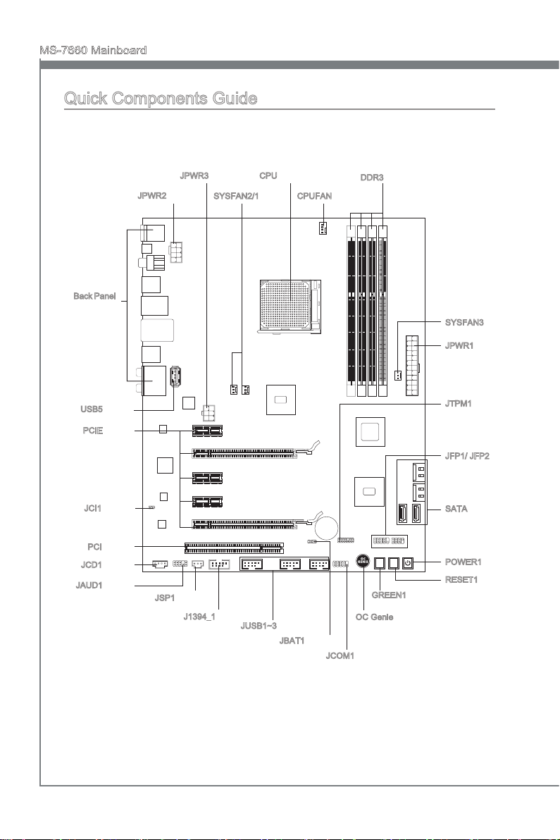
Quick Components Guide
Back Panel,
En-13
USB5, En-18
PCIE, En-24
JCI1, En-15
PCI, En-25
JCD1, En-18
JAUD1, En-16
JPWR3, En-12
JPWR2, En-11
JSP1, En-17
SYSFAN2/1, En-16
J1394_1, En-19
CPU, En-6
JUSB1~3, En-18
JBAT1, En-21
CPUFAN, En-16
JCOM1, En-19
DDR3, En-9
GREEN1, En-22
OC Genie, En-23
SYSFAN3, En-16
JPWR1, En-11
JTPM1, En-20
JFP1/ JFP2, En-17
SATA, En-15
POWER1, En-22
RESET1, En-22
En-4
English
RESET
Green
Power
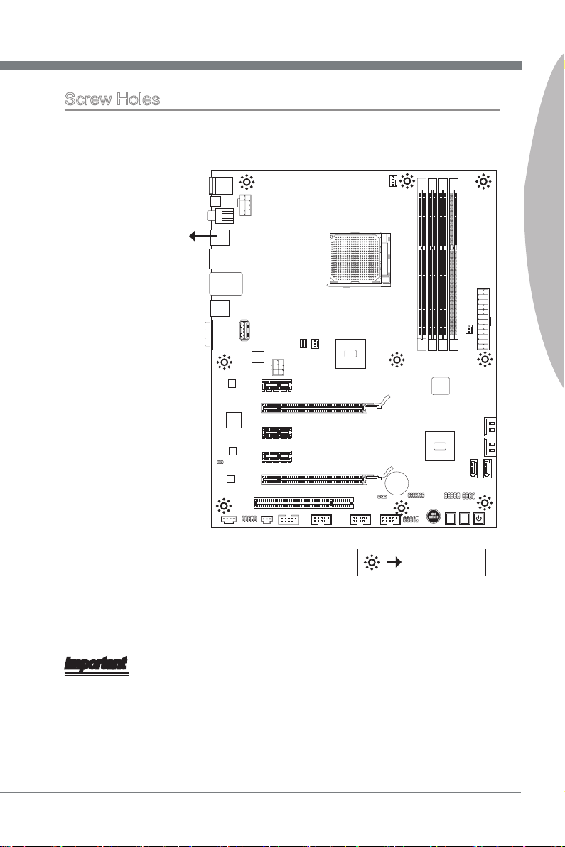
Screw Holes
When you install the mainboard, you have to place the mainboard into the chassis in the
correct direction. The locations of screws holes on the mainboard are shown as below.
The side has to toward
the rear, the position
for the I/O shield of the
chassis.
English
Screw holes
Refer above picture to install standos in the appropriate locations on chassis and then
screw through the mainboard screw holes into the standos.
Important
To prevent damage to the mainboard, any contact between the mainboard circuit and
•
chassis or unnecessary standos mounted on the chassis is prohibited.
Please make sure there are no metal components placed on the mainboard or within
•
the chassis that may cause short circuit of the mainboard.
En-5
MS-7660 Mainboard
English
CPU (Central Processing Unit)
When you are installing the CPU, make sure to install the cooler to prevent overheating.
If you do not have the CPU cooler, consult your dealer before turning on the computer.
For the latest information about CPU, please visit http://www.msi.com/index.
php?func=cpuform2
Important
Overheating
Overheating will seriously damage the CPU and system. Always make sure the cooling
fan can work properly to protect the CPU from overheating. Make sure that you apply
an even layer of thermal paste (or thermal tape) between the CPU and the heatsink to
enhance heat dissipation.
Replacing the CPU
While replacing the CPU, always turn o the ATX power supply or unplug the power
supply’s power cord from the grounded outlet rst to ensure the safety of CPU.
Overclocking
This mainboard is designed to support overclocking. However, please make sure your
components are able to tolerate such abnormal setting, while doing overclocking. Any
attempt to operate beyond product specications is not recommended. We do not guarantee the damages or risks caused by inadequate operation or beyond product specications.
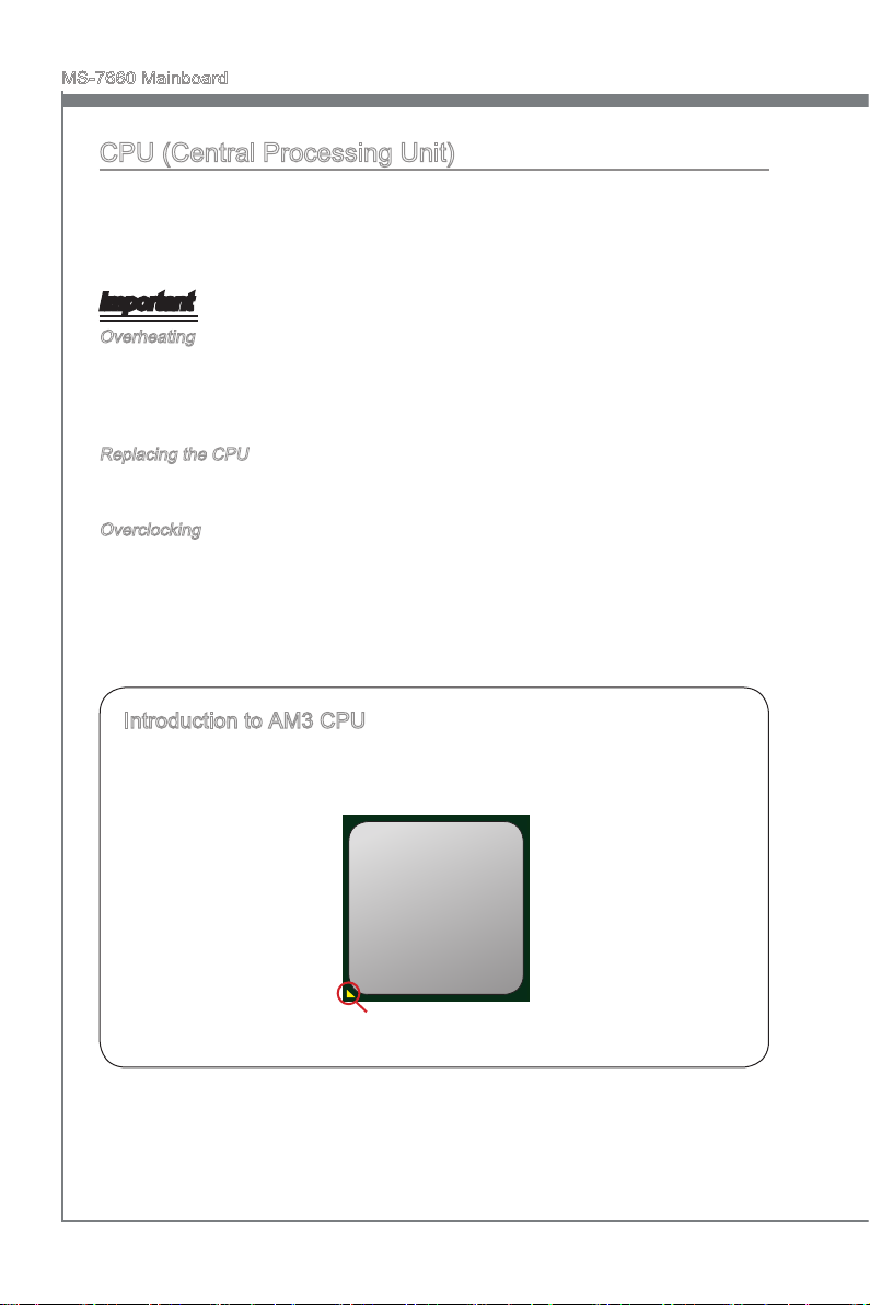
Introduction to AM3 CPU
The surface of CPU. Remember to apply some thermal paste on it for better heat
dispersion.
Gold arrow
En-6
English
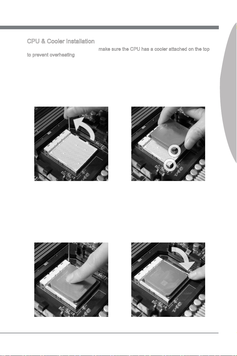
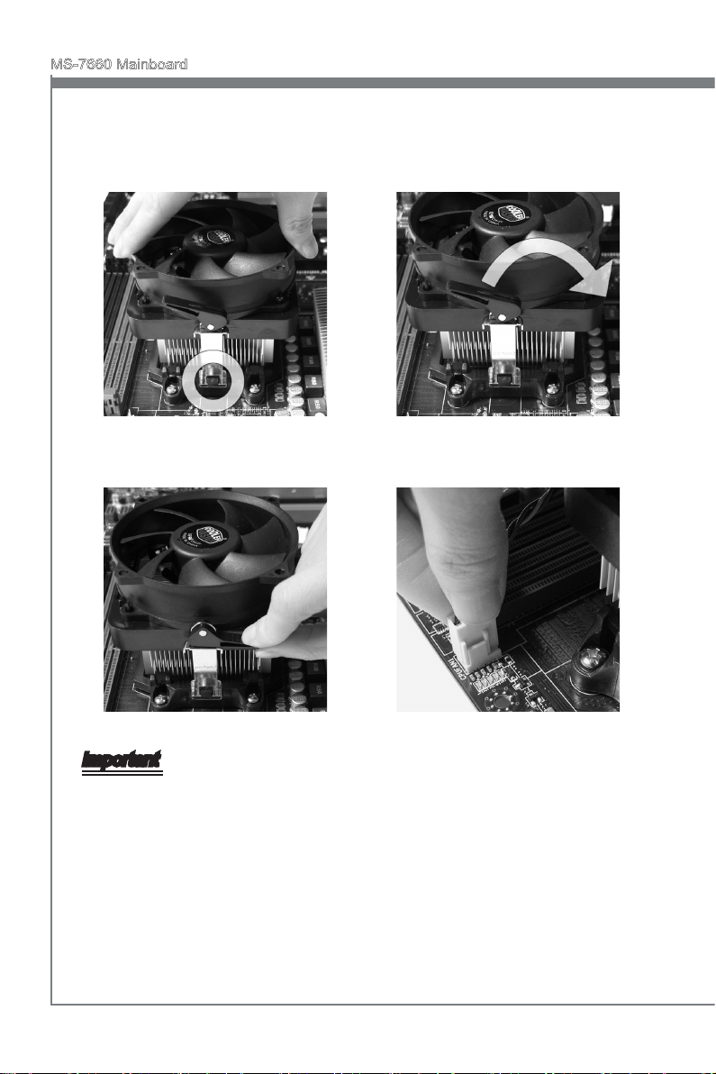
CPU & Cooler Installation
When you are installing the CPU, make sure the CPU has a cooler attached on the top
to prevent overheating. Meanwhile, do not forget to apply some thermal paste on CPU
before installing the heat sink/cooler fan for better heat dispersion.
Follow the steps below to install the CPU & cooler correctly. Wrong installation will
cause the damage of your CPU & mainboard
Pull the lever sideways away from
1.
the socket. Make sure to raise the
lever up to a 90-degree angle.
If the CPU is correctly installed, the
3. Press the CPU down rmly into the
pins should be completely embedded
into the socket and can not be seen.
Please note that any violation of the
correct installation procedures may
cause permanent damages to your
mainboard.
Look for the gold arrow of the CPU.
2.
The gold arrow should point as shown
in the picture. The CPU can only t in
the correct orientation.
4.
socket and close the lever. As the
CPU is likely to move while the lever
is being closed, always close the lever with your ngers pressing tightly
on top of the CPU to make sure the
CPU is properly and completely embedded into the socket.
English
En-7
MS-7660 Mainboard
English
Position the cooling set onto the re-
5. Then press down the other end of the
tention mechanism.
Hook one end of the clip to hook
rst.
6.
clip to fasten the cooling set on the
top of the retention mechanism.
Locate the Fix Lever and lift up it.
Fasten down the lever.7. Attach the CPU Fan cable to the CPU
8.
fan connector on the mainboard.
Important
Mainboard photos shown in this section are for demonstration only. The appearance
•
of your mainboard may vary depending on the model you purchase.
While disconnecting the Safety Hook from the xed bolt, it is necessary to keep an
•
eye on your ngers, because once the Safety Hook is disconnected from the xed
bolt, the xed lever will spring back instantly.
En-8
English
Memory
These DIMM slots are used for installing memory modules. For more information on
compatible components, please visit
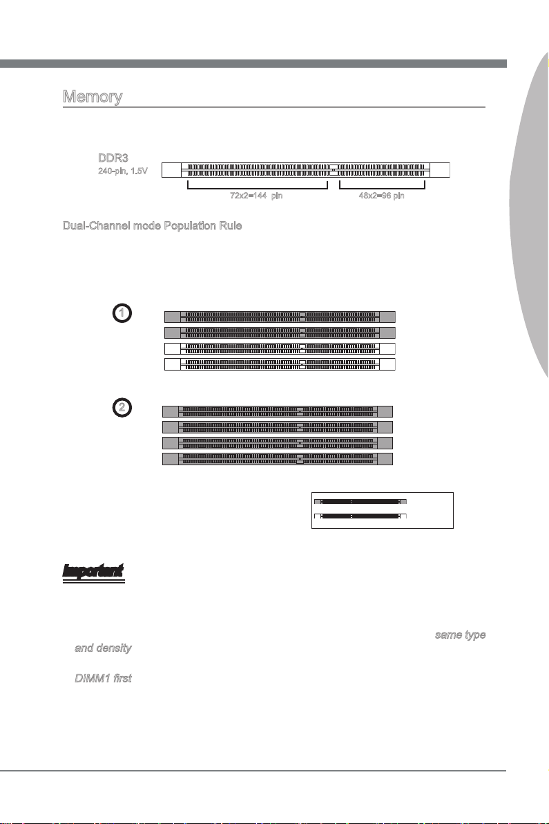
DDR3
240-pin, 1.5V
Dual-Channel mode Population Rule
In Dual-Channel mode, the memory modules can transmit and receive data with two
data bus lines simultaneously. Enabling Dual-Channel mode can enhance the system
performance. The following illustrations explain the population rules for Dual-Channel
mode.
http://www.msi.com/index.php?func=testreport
48x2=96 pin 72x2=144 pin
English
DIMM2
DIMM3
DIMM4
1
DIMM1
2
DIMM1
DIMM2
DIMM3
DIMM4
Installed
Empty
Important
DDR3 memory modules are not interchangeable with DDR2 and the DDR3 standard
•
is not backwards compatible. You should always install DDR3 memory modules in
the DDR3 DIMM slots.
In Dual-Channel mode, make sure that you install memory modules of the same type
•
and density in dierent channel DIMM slots.
To ensure a successful system boot-up, always insert the memory modules into the
•
DIMM1 rst.
Due to the chipset resource deployment , the system density will only be detected up
•
to 15+GB (not full 16GB) when each DIMM is installed with a 4GB memory module.
En-9
MS-7660 Mainboard
English
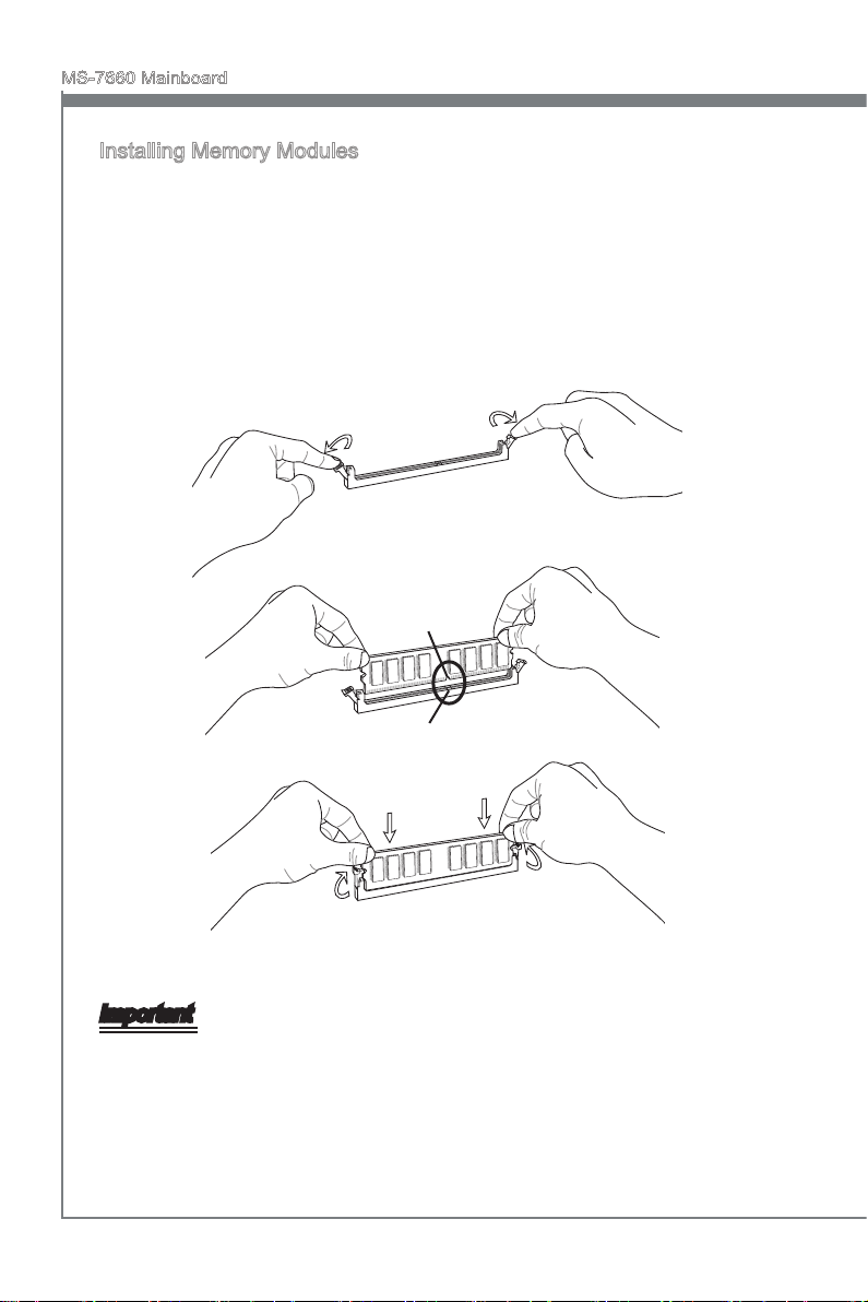
Installing Memory Modules
The memory module has only one notch on the center and will only t in the right
1.
orientation.
Insert the memory module vertically into the DIMM slot. Then push it in until the
2.
golden nger on the memory module is deeply inserted in the DIMM slot. The plastic
clip at each side of the DIMM slot will automatically close when the memory module
is properly seated.
Manually check if the memory module has been locked in place by the DIMM slot
3.
clips at the sides.
Notch
Volt
Important
You can barely see the golden nger if the memory module is properly inserted in the
DIMM slot.
En-10
English
Power Supply
13 .+3 .3
V
1. +3. 3
V
14 .-1 2V
2. +3. 3
V
15 .Gr oun d
3
.G rou nd
16 .PS -ON
#
4. +5
V
17 .Gr oun d
5
.G rou nd
18 .Gr oun d
6. +5
V
19 .Gr oun d
7
.G rou nd
22 .+5
V
10 .+1 2V
20 .Re s
8. PW
R O
K
23 .+5
V
11
.+ 12V
21 .+5
V
9. 5VS B
24 .Gr oun d
12 .+3 .3
V
7. +12 V
3.
Gr oun d
5. +12 V
1.
Gr oun d
8. +12 V
4
.G rou nd
6. +12 V
2
.G rou nd
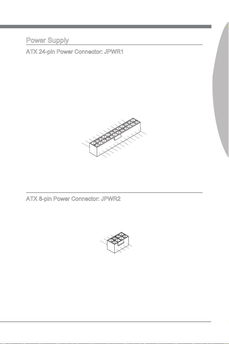
ATX 24-pin Power Connector: JPWR1
This connector allows you to connect an ATX 24-pin power supply. To connect the ATX
24-pin power supply, make sure the plug of the power supply is inserted in the proper
orientation and the pins are aligned. Then push down the power supply rmly into the
connector.
You may use the 20-pin ATX power supply as you like. If you’d like to use the 20-pin
ATX power supply, please plug your power supply along with pin 1 & pin 13.
ATX 8-pin Power Connector: JPWR2
This connector provides 12V power output to the CPU.
English
En-11
MS-7660 Mainboard
English
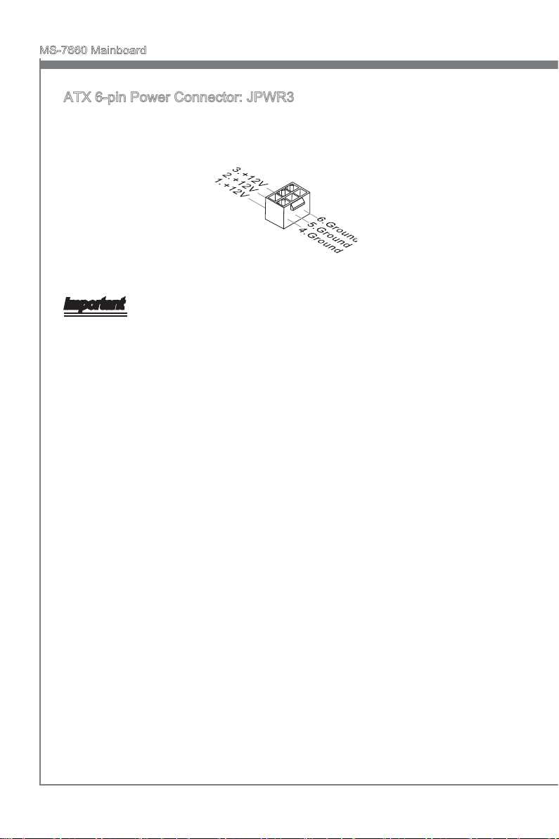
ATX 6-pin Power Connector: JPWR3
This connector is used to provide power to the graphics card.
Important
Make sure that all the connectors are connected to proper ATX power supplies to ensure stable operation of the mainboard.
En-12
English
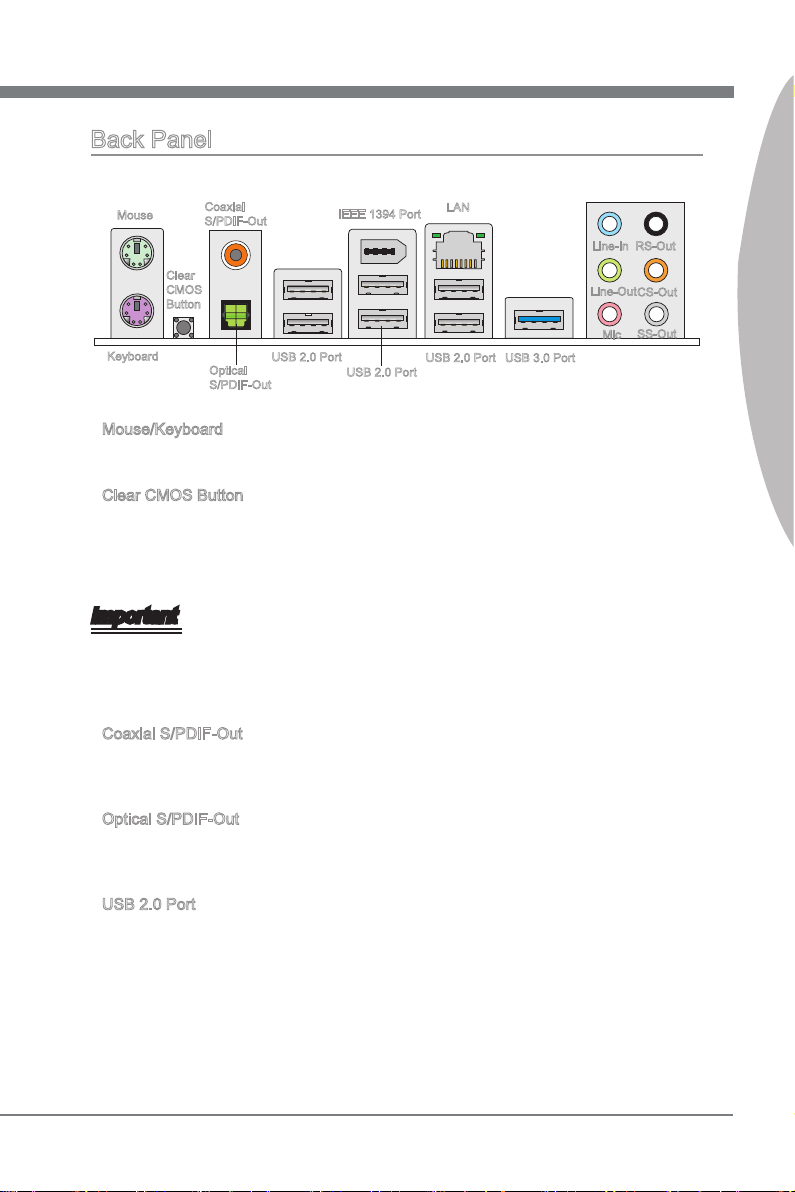
Back Panel
Mouse
Clear
CMOS
Button
Keyboard
Mouse/Keyboard
▶
Coaxial
S/PDIF-Out
Optical
S/PDIF-Out
USB 2.0 Port
IEEE 1394 Port
USB 2.0 Port
LAN
USB 2.0 Port
USB 3.0 Port
Line-In
Line-Out
Mic
RS-Out
CS-Out
SS-Out
The standard PS/2® mouse/keyboard DIN connector is for a PS/2® mouse/keyboard.
Clear CMOS Button
▶
There is a CMOS RAM on board with an external battery power supply to preserve the
system conguration data. With the CMOS RAM, the system can automatically boot
OS every time it is turned on. If you want to clear the system conguration, use the
button to clear data. Press the button to clear the data.
Important
Make sure that you power o the system before clearing CMOS data.
After pressing this button to clear CMOS data in power o (G3) state, the system will
boot automatically.
Coaxial S/PDIF-Out
▶
This S/PDIF (Sony & Philips Digital Interconnect Format) connector is provided for digi-
tal audio transmission to external speakers through a coaxial cable.
English
Optical S/PDIF-Out
▶
This S/PDIF (Sony & Philips Digital Interconnect Format) connector is provided for digi-
tal audio transmission to external speakers through an optical ber cable.
USB 2.0 Port
▶
The USB (Universal Serial Bus) port is for attaching USB devices such as keyboard,
mouse, or other USB-compatible devices. Supports data transfer rate up to 480Mbit/s
(Hi-Speed).
En-13
MS-7660 Mainboard
English
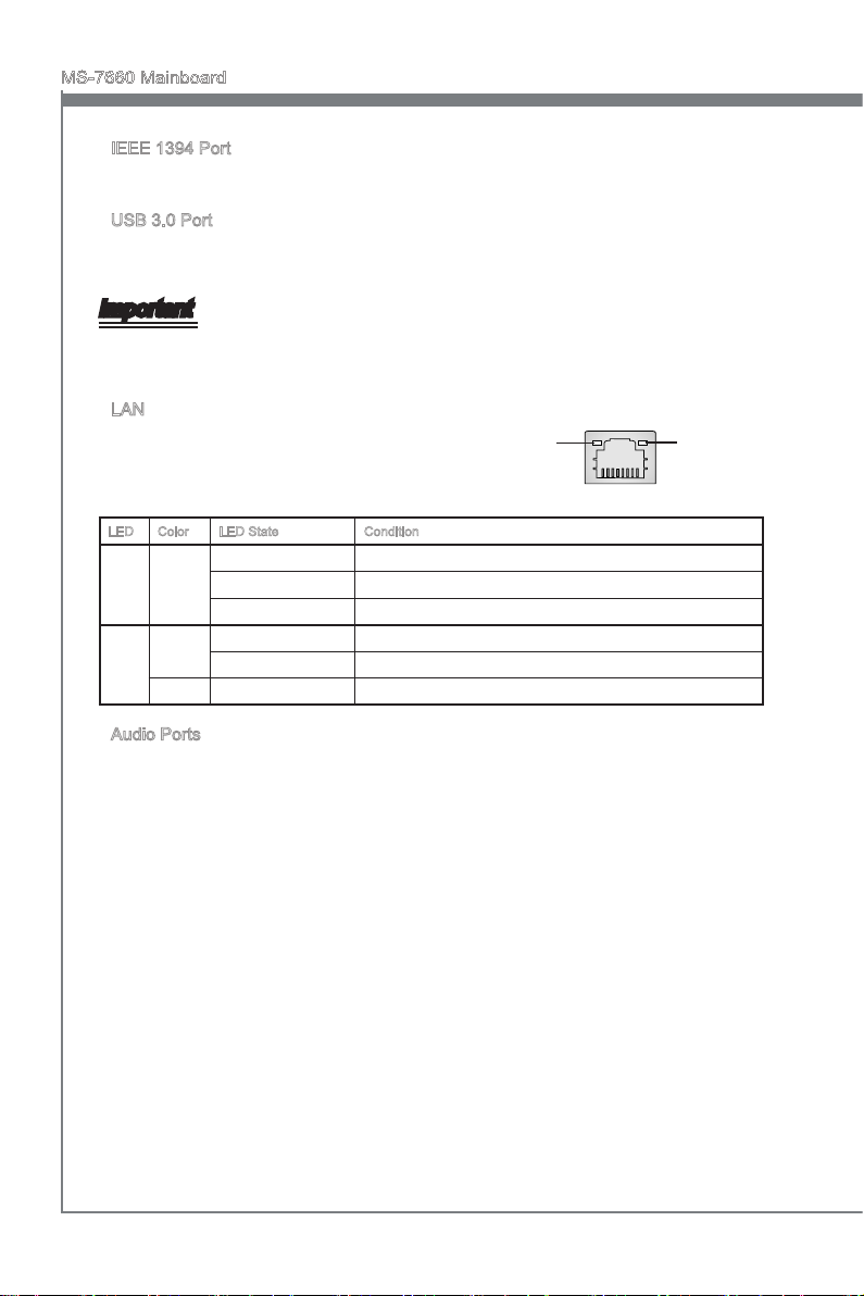
IEEE 1394 Port
▶
The IEEE 1394 port on the back panel provides connection to IEEE 1394 devices.
USB 3.0 Port
▶
USB 3.0 port is backward-compatible with USB 2.0 devices. It supports data transfer
rate up to 5 Gbit/s (SuperSpeed).
Important
If you want to use a USB 3.0 device, you must use the USB 3.0 cable to connect to
the USB 3.0 port.
LAN
▶
The standard RJ-45 LAN jack is for connection to the
Local Area Network (LAN). You can connect a network cable to it.
LED Color LED State Condition
Left Yellow O LAN link is not established.
On(Steady state) LAN link is established.
On(brighter & pulsing) The computer is communicating with another computer on the LAN.
Right Green O 10 Mbits/sec data rate is selected.
On 100 Mbits/sec data rate is selected.
Orange On 1000 Mbits/sec data rate is selected.
Yellow Green/ Orange
Audio Ports
▶
These audio connectors are used for audio devices. It is easy to dierentiate between
audio eects according to the color of audio jacks.
Line-In (Blue) - Line In, is used for external CD player, tape-player or other
■
audio devices.
Line-Out (Green) - Line Out, is a connector for speakers or headphones.
■
Mic (Pink) - Mic, is a connector for microphones.
■
RS-Out (Black) - Rear-Surround Out in 4/ 5.1/ 7.1 channel mode.
■
CS-Out (Orange) - Center/ Subwoofer Out in 5.1/ 7.1 channel mode.
■
SS-Out (Gray) - Side-Surround Out 7.1 channel mode.
■
En-14
English
Connectors
1
.
C
I
N
T
R
U
2
.
G
r
o
u
n
d
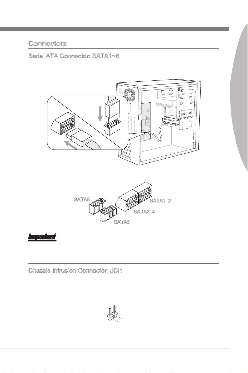
Serial ATA Connector: SATA1~6
This connector is a high-speed Serial ATA interface port. Each connector can connect
to one Serial ATA device.
* The MB layout in this gure is for reference only.
English
SATA5
SATA6
SATA1_2
SATA3_4
Important
Please do not fold the Serial ATA cable into a 90-degree angle. Otherwise, data loss
may occur during transmission.
Chassis Intrusion Connector: JCI1
This connector connects to the chassis intrusion switch cable. If the chassis is opened,
the chassis intrusion mechanism will be activated. The system will record this status
and show a warning message on the screen. To clear the warning, you must enter the
BIOS utility and clear the record.
En-15
MS-7660 Mainboard
English
1
.G rou nd
2. +12 V
3. Sen sor
/ N
o U
se
1
.
G
r
o
u
n
d
2
.
+
1
2
V
3
.
S
e
n
s
o
r
4
.
C
o
n
t
r
o
l
1
.
M
I
C
L
3
.
M
I
C
R
1
0
.
H
e
a
d
P
h
o
n
e
D
e
t
e
c
t
i
o
n
5
.
H
e
a
d
P
h
o
n
e
R
7
.
S
E
N
S
E
_
S
E
N
D
9
.
H
e
a
d
P
h
o
n
e
L
8
.
N
o
P
i
n
6
.
M
I
C
D
e
t
e
c
t
i
o
n
4
.
P
R
E
S
E
N
C
E
#
2
.
G
r
o
u
n
d
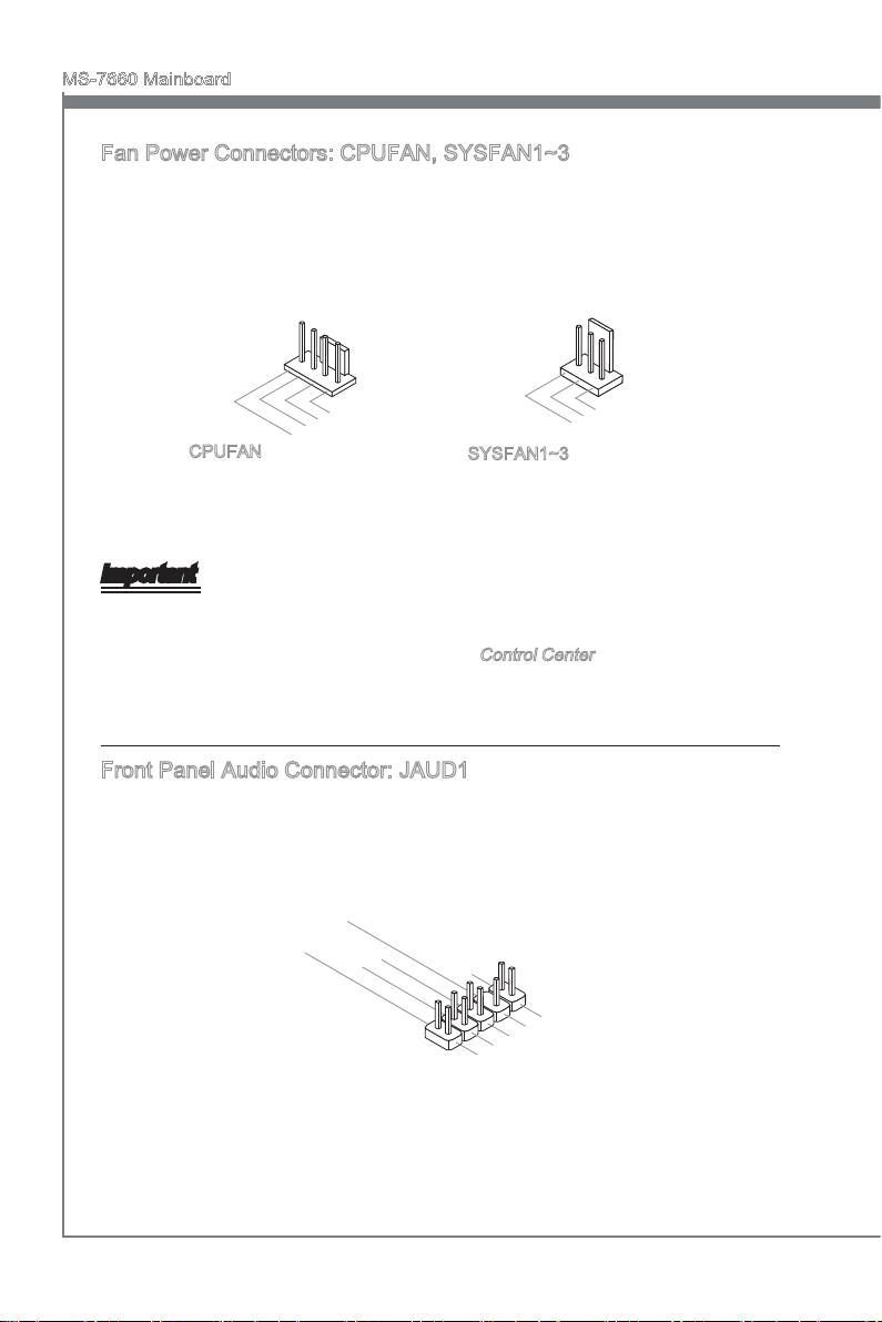
Fan Power Connectors: CPUFAN, SYSFAN1~3
The fan power connectors support system cooling fan with +12V. When connecting the
wire to the connectors, always note that the red wire is the positive and should be connected to the +12V; the black wire is Ground and should be connected to GND. If the
mainboard has a System Hardware Monitor chipset on-board, you must use a specially
designed fan with speed sensor to take advantage of the CPU fan control.
CPUFAN
SYSFAN1~3
Important
Please refer to the recommended CPU fans at processor’s ocial website or consult
•
the vendors for proper CPU cooling fan.
CPUFAN supports fan control. You can install Control Center utility that will automati-
•
cally control the CPU fan speed according to the actual CPU temperature.
Fan cooler set with 3 or 4 pins power connector are both available for CPUFAN.
•
Front Panel Audio Connector: JAUD1
This connector allows you to connect the front panel audio and is compliant with Intel
Front Panel I/O Connectivity Design Guide.
®
En-16
English
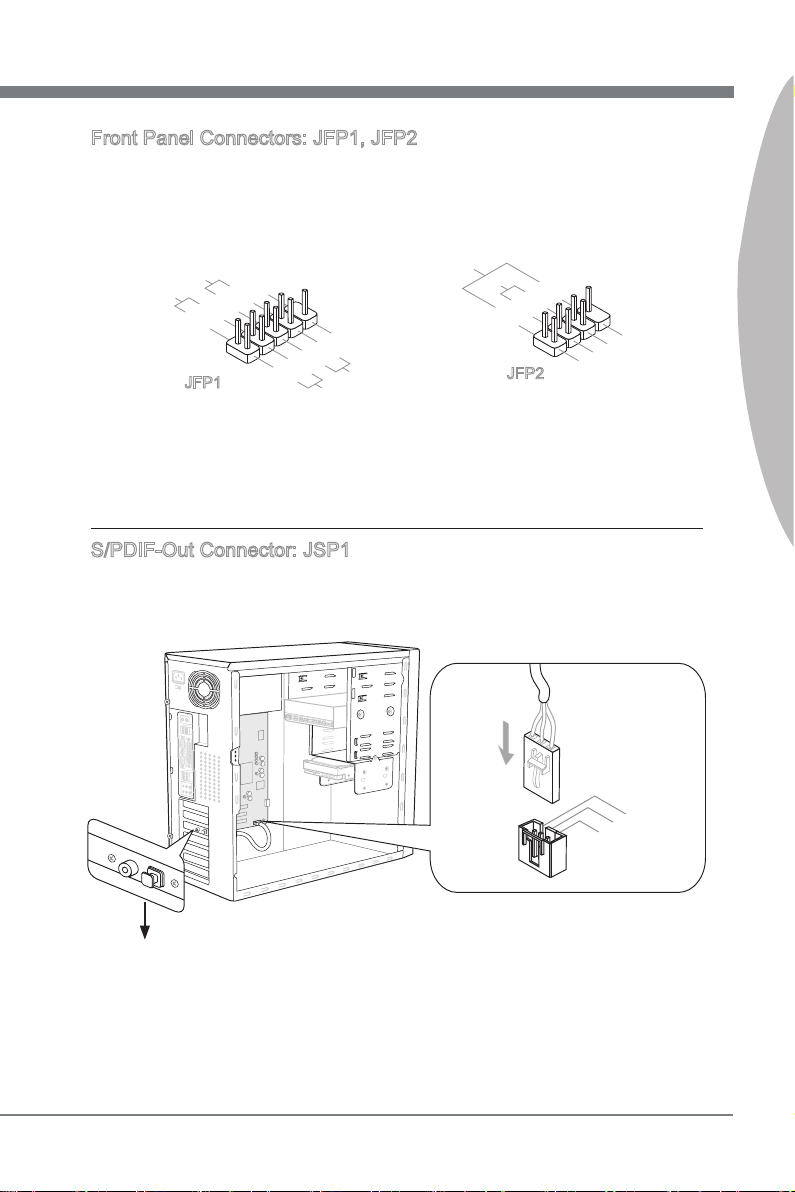
Front Panel Connectors: JFP1, JFP2
1
.Grou nd
3.Sus pen d
LE
D
5.Pow er
LE
D
7.No Pi
n
8.
+
6.
-
4.
+
2.
-
Buzze r
S
peake r
1. +
3.
-
10 .No
Pi
n
5.
Re set
S
wi tch
HD D
LE
D
P
ow er
S
wi tch
P
ow er
LE
D
7.
+
9. Res erv e
d
8.
-
6.
+
4.
-
2.
+
11
5V
3. VC
C
2. SPD IF
1
.G rou nd
These connectors are for electrical connection to the front panel switches and LEDs.
The JFP1 is compliant with Intel® Front Panel I/O Connectivity Design Guide.
English
JFP1
JFP2
S/PDIF-Out Connector: JSP1
This connector is used to connect S/PDIF (Sony & Philips Digital Interconnect Format)
interface for digital audio transmission.
* The MB layout in this gure is for reference only.
S/PDIF-Out Bracket (optional)
En-17
MS-7660 Mainboard
English
4
.
R
3
.
G
r
o
u
n
d
2
.
G
r
o
u
n
d
1
.
L
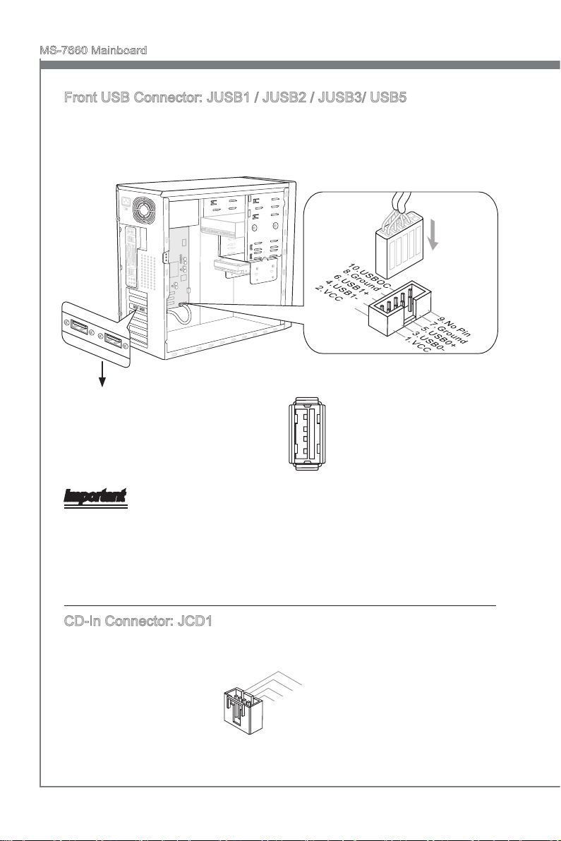
Front USB Connector: JUSB1 / JUSB2 / JUSB3/ USB5
This connector, compliant with Intel® I/O Connectivity Design Guide, is ideal for connecting high-speed USB interface peripherals such as USB HDD, digital cameras, MP3
players, printers, modems and the like.
USB 2.0 connector:
JUSB1/ JUSB2/ JUSB3
* The MB layout in this gure is for reference only.
USB 2.0 Bracket (optional)
USB 3.0 connector: USB5
Important
Note that the pins of VCC and GND must be connected correctly to avoid possible
•
damage.
If you want to use a USB 3.0 device, you must use the USB 3.0 cable to connect to
•
the USB 3.0 port.
CD-In Connector: JCD1
This connector is provided for external audio input.
En-18
English
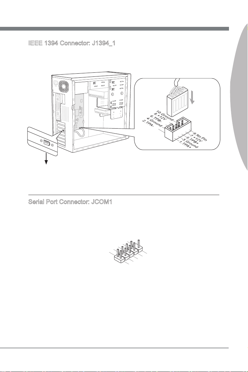
IEEE 1394 Connector: J1394_1
1
.
D
C
D
3
.
S
O
U
T
1
0
.
N
o
P
i
n
5
.
G
r
o
u
n
d
7
.
R
T
S
9
.
R
I
8
.
C
T
S
6
.
D
S
R
4
.
D
T
R
2
.
S
I
N
This connector allows you to connect the IEEE 1394 device via an optional IEEE1394
bracket.
* The MB layout in this gure is for reference only.
1394 Bracket (optional)
Serial Port Connector: JCOM1
This connector is a 16550A high speed communication port that sends/ receives 16
bytes FIFOs. You can attach a serial device.
English
En-19
MS-7660 Mainboard
English
1
0
.
N
o
P
i
n
1
4
.
G
r
o
u
n
d
8
.
5
V
P
o
w
e
r
1
2
.
G
r
o
u
n
d
6
.
S
e
r
i
a
l
I
R
Q
4
.
3
.
3
V
P
o
w
e
r
2
.
3
V
S
t
a
n
d
b
y
p
o
w
e
r
1
.
L
P
C
C
l
o
c
k
3
.
L
P
C
R
e
s
e
t
5
.
L
P
C
a
d
d
r
e
s
s
&
d
a
t
a
p
i
n
0
7
.
L
P
C
a
d
d
r
e
s
s
&
d
a
t
a
p
i
n
1
9
.
L
P
C
a
d
d
r
e
s
s
&
d
a
t
a
p
i
n
2
1
1
.
L
P
C
a
d
d
r
e
s
s
&
d
a
t
a
p
i
n
3
1
3
.
L
P
C
F
r
a
m
e
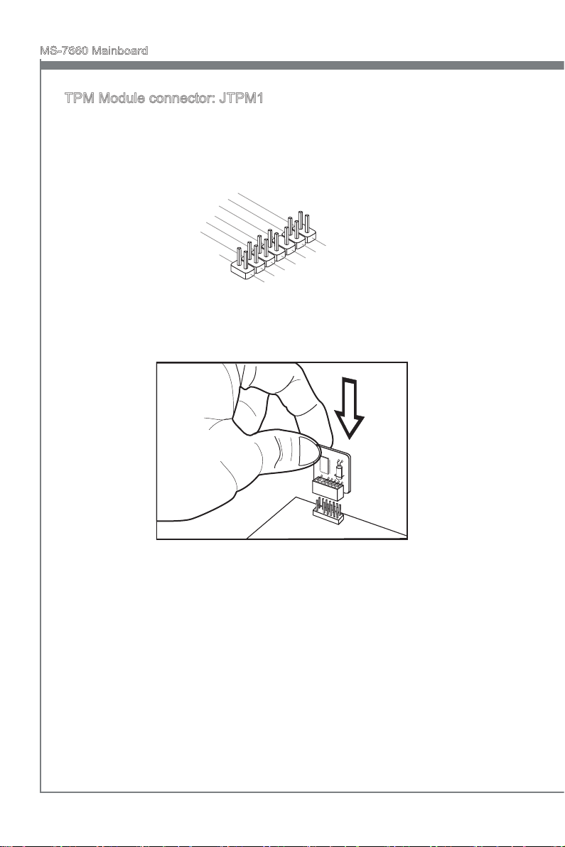
TPM Module connector: JTPM1
This connector connects to a TPM (Trusted Platform Module) module (optional). Please
refer to the TPM security platform manual for more details and usages.
En-20

English
Jumper
Clear CMOS Jumper: JBAT1
There is a CMOS RAM on board with an external battery power supply to preserve the
system conguration data. With the CMOS RAM, the system can automatically boot OS
every time it is turned on. If you want to clear the system conguration, set the jumper
to clear data.
1 11
JBAT1 Keep Data Clear Data
Important
You can clear CMOS by shorting 2-3 pin while the system is o. Then return to 1-2
pin position. Avoid clearing the CMOS while the system is on; it will damage the mainboard.
English
En-21

MS-7660 Mainboard
English
Button
The mainboard provides the following buttons for you to set the computer’s function.
This section will explain how to change your mainboard’s function through the use of
button.
Power Button: POWER1
This button is used to turn-on or turn-o the system. Press the button to turn-on or
turn-o the system.
Reset Button: RESET1
This button is used to reset the system. Press the button to reset the system.
GreenPower Button: GREEN1
This button is used to switch LED function of system. Once you press the button, the
system will switch the LED between on and o mode.
En-22

English
OC Genie Button: OC Genie
This button is used to auto-overclock the system. When the system is in a power o
state, pressing the button will enable OC Genie. The button will light up and lock into
place. After booting up, the system will automatically detect the optimum values to
overclock. To disable the OC Genie function, please press the button again after powering o the system. The button light will turn o, and the system will restore the default
setting.
Important
When using OC Genie, installation of DDR3 1333 and up memory and a better CPU
•
cooler is highly recommended.
We do not guarantee the OC Genie overclocking range and the damages or risks
•
caused by the OC Genie overclocking behavior.
You can disable the OC Genie function in BIOS setup. And we suggest you to save
•
the OC Genie conguration to overclocking prole in BIOS for future using.
The usage of OC Genie is at your own risk. Overclocking is never guaranteed by
•
MSI.
English
En-23

MS-7660 Mainboard
English
Slots
PCIE (Peripheral Component Interconnect Express) Slot
The PCIE slot supports the PCIE interface expansion card.
PCIE x16 Slot
PCIE x1 Slot
Important
When adding or removing expansion cards, make sure that you unplug the power supply rst. Read the documentation for the expansion card to congure any necessary
hardware or software settings for it, such as jumpers, switches or BIOS conguration.
En-24

English
PCI (Peripheral Component Interconnect) Slot
The PCI slot supports LAN card, SCSI card, USB card, and other add-on cards that
comply with PCI specications.
32-bit PCI Slot
Important
When adding or removing expansion cards, make sure that you unplug the power supply rst. Read the documentation for the expansion card to congure any necessary
hardware or software settings for it, such as jumpers, switches or BIOS conguration.
PCI Interrupt Request Routing
IRQ, or interrupt request line, are hardware lines over which devices can send interrupt
signals to the microprocessor. The PCI IRQ pins are typically connected to the PCI bus
pins as follows:
Order1 Order2 Order3 Order4
PCI Slot1 INT E# INT F# INT G# INT H#
English
En-25

MS-7660 Mainboard
English
CPU NB P hase LED s CP U Pha se LE Ds
HDD LED
Gre enPo wer/ Res et/ P ower LED s
RESET
Green
Power
LED Status Indicators
CPU NB Phase LEDs
These LEDs indicate the current CPU-NB power phase mode. Follow the instructions
below to read.
Lights O
CPU-NB is in 1 phase power mode. CPU-NB is in 2 phase power mode.
En-26

English
CPU Phase LEDs
These LEDs indicate the current CPU power phase mode. Follow the instructions below
to read.
Lights O
CPU is in 2 phase power mode.
CPU is in 4 phase power mode.
CPU is in 6 phase power mode.
CPU is in 8 phase power mode.
Power LED
Every time you press the power button and it is functional, the power LED will blink
once.
Reset LED
Every time you press the reset button and it is functional, the reset LED will blink once.
GreenPower LED
Lights when you press the GreenPower button to switch the LED function of system
on.
English
HDD LED
Lights when the hard drive is operating.
En-27

MS-7660 Mainboard
English
BIOS Setup
This chapter provides basic information on the BIOS Setup program and allows you to
congure the system for optimum use. You may need to run the Setup program when:
An error message appears on the screen during the system booting up, and
■
requests you to run BIOS SETUP.
You want to change the default settings for customized features.
■
Important
The items under each BIOS category described in this chapter are under continuous
•
update for better system performance. Therefore, the description may be slightly different from the latest BIOS and should be held for reference only.
Upon boot-up, the 1st line appearing after the memory count is the BIOS version. It is
•
usually in the format:
A7660AMS V1.X 061410 where:
1st digit refers to BIOS maker as A = AMI, W = AWARD, and P = PHOENIX.
2nd - 5th digit refers to the model number.
6th digit refers to the chipset as I = Intel, N = NVIDIA, A = AMD and V = VIA.
7th - 8th digit refers to the customer as MS = all standard customers.
V1.X refers to the BIOS version.
061410 refers to the date this BIOS was released.
En-28

English
Entering Setup
Power on the computer and the system will start POST (Power On Self Test) process.
When the message below appears on the screen, press <DEL> key to enter Setup.
Press DEL to enter SETUP
If the message disappears before you respond and you still wish to enter Setup, restart
the system by turning it OFF and On or pressing the RESET button. You may also restart the system by simultaneously pressing <Ctrl>, <Alt>, and <Delete> keys.
Getting Help
After entering the Setup menu, the rst menu you will see is the Main Menu.
Main Menu
The main menu lists the setup functions you can make changes to. You can use the
arrow keys ( ↑↓ ) to select the item. The on-line description of the highlighted setup
function is displayed at the bottom of the screen.
Sub-Menu
If you nd a right pointer symbol appears to the left of certain elds that means a sub-
menu can be launched from this eld. A sub-menu contains additional options for a
eld parameter. You can use arrow keys ( ↑↓ ) to highlight the eld and press <Enter>
to call up the sub-menu. Then you can use the control keys to enter values and move
from eld to eld within a sub-menu. If you want to return to the main menu, just press
the <Esc >.
General Help <F1>
The BIOS setup program provides a General Help screen. You can call up this screen
from any menu by simply pressing <F1>. The Help screen lists the appropriate keys to
use and the possible selections for the highlighted item. Press <Esc> to exit the Help
screen.
English
En-29

MS-7660 Mainboard
English
The Main Menu
Once you enter BIOS CMOS Setup Utility, the Main Menu will appear on the screen.
The Main Menu allows you to select from the setup functions and two exit choices.
Use arrow keys to select among the items and press <Enter> to accept or enter the
sub-menu.
Standard CMOS Features
▶
Use this menu for basic system congurations, such as time, date etc.
Advanced BIOS Features
▶
Use this menu to setup the items of the BIOS special enhanced features.
Integrated Peripherals
▶
Use this menu to specify your settings for integrated peripherals.
Power Management Setup
▶
Use this menu to specify your settings for power management.
H/W Monitor
▶
This entry shows your PC health status.
Green Power
▶
Use this menu to specify the power phase.
BIOS Setting Password
▶
Use this menu to set the password for BIOS.
Cell Menu
▶
Use this menu to specify your settings for frequency/voltage control and overclocking.
En-30

English
M-Flash
▶
Use this menu to read/ ash the BIOS from storage drive (FAT/ FAT32 format only).
Overclocking Prole
▶
Use this menu to save/ load your settings to/ from CMOS for BIOS.
Load Fail-Safe Defaults
▶
Use this menu to load the default values set by the BIOS vendor for stable system
performance.
Load Optimized Defaults
▶
Use this menu to load the default values set by the mainboard manufacturer specically
for optimal performance of the mainboard.
Save & Exit Setup
▶
Save changes to CMOS and exit setup.
Exit Without Saving
▶
Abandon all changes and exit setup.
English
En-31

MS-7660 Mainboard
English
When enter the BIOS Setup utility, follow the processes below for general use.
Load Optimized Defaults : Use control keys (↑↓) to highlight the Load Optimized
1.
Defaults eld and press <Enter> , a message as below appears:
Select [Ok] and press Enter to load the default settings for optimal system performance.
Setup Date/ Time : Select the Standard CMOS Features and press <Enter> to enter
2.
the Standard CMOS Features-menu. Adjust the Date, Time elds.
Save & Exit Setup : Use control keys (↑↓) to highlight the Save & Exit Setup eld
3.
and press <Enter> , a message as below appears:
Select [Ok] and press Enter to save the congurations and exit BIOS Setup utility.
Important
The conguration above are for general use only. If you need the detailed settings of
BIOS, please see the English manual on MSI website.
En-32

English
Cell Menu Introduction : This menu is for advanced user who want to overclock the
4.
mainboard.
Important
Change these settings only if you are familiar with the chipset.
Current CPU / DRAM / CPU-NB Frequency
▶
These items show the current clocks of CPU, Memory and CPU-NB speed. Read-only.
CPU Specications
▶
Press <Enter> to enter the sub-menu. This submenu shows the information of installed
CPU.
CPU Technology Support
▶
Press <Enter> to enter the sub-menu. This sub-menu shows the technologies that
the installed CPU supported.
CPU Feature
▶
Press <Enter> to enter the sub-menu.
AMD Cool’n’Quiet
▶
The Cool’n’Quiet technology can eectively and dynamically lower CPU speed and
power consumption.
English
Important
To ensure that Cool’n’Quiet function is activated and will be working properly, it is required to double conrm that:
Run BIOS Setup, and select Cell Menu. Under Cell Menu, nd AMD Cool’n’Quiet,
•
and set this item to “Enabled”.
En-33

MS-7660 Mainboard
English
Enter Windows, and select [Start]->[Settings]->[Control Panel]->[Power Options].
•
Enter Power Options Properties tag, and select Minimal Power Management under
Power schemes.
C1E Support
▶
To enable this item to read the CPU power consumption while idle. Not all proces-
sors support Enhanced Halt state (C1E).
SVM Support
▶
This item is used to enable/ disable SVM.
AMD Cool’n’Quiet
▶
The Cool’n’Quiet technology can eectively and dynamically lower CPU speed and
power consumption.
C1E Support
▶
To enable this item to read the CPU power consumption while idle. Not all processors
support Enhanced Halt state (C1E).
Adjust CPU FSB Frequency (MHz)
▶
This item allows you to select the CPU Front Side Bus clock frequency (in MHz).
OC Stepping
▶
This item will be enabled after you set the overclocking frequency in the “Adjust CPU
FSB Frequency (MHz)”. And the following items will appear. This items will help the
system to overclock step by step after system booting up.
Start OC Stepping From (MHz)
▶
This item is used to set the initial FSB clock. The system will boot with the initial FSB
clock, and start to overclock from initial FSB clock to set FSB clock that you set in
“Adjust CPU FSB Frequency (MHz)” step by step.
OC Step
▶
This item is used to set how many steps for FSB colck overclocking.
OC Step Count Timer
▶
This item is used to set the buer time for every step.
Adjust CPU Ratio
▶
This item is used to adjust CPU clock multiplier (ratio). It is available only when the
processor supports this function.
Adjusted CPU Frequency (MHz)
▶
It shows the adjusted CPU frequency. Read-only.
Adjust CPU-NB Ratio
▶
This item is used to adjust CPU-NB ratio.
Adjusted CPU-NB Frequency (MHz)
▶
It shows the adjusted CPU NB frequency. Read-only.
En-34
English
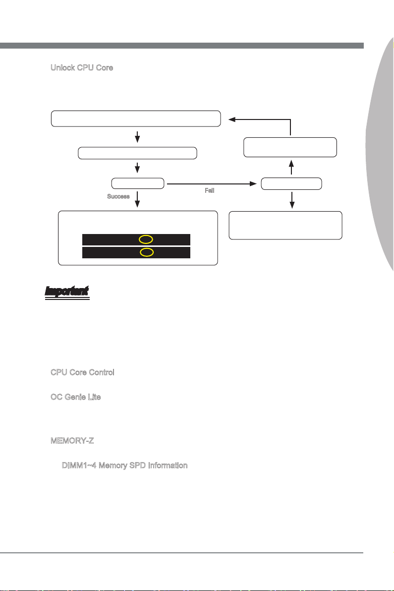
Unlock CPU Core
▶
This item is used to unlock the CPU core. Please refer to the procedures below for CPU
core unlocked in BIOS setup.
Enter “Cell Menu” and set “Unlock CPU Core” to [Enabled].
Set “Adjust CPU-NB Ratio” and
Save changes and exit the BIOS setup.
“HT Link Speed” to [x8].
English
System restart.
Success
You will see the “X4” (quad core) or “X2” (dual core for
Sempron series only) during POST.
AMD Phenom(tm) II X4 Processor
AMD Sempron(tm) II X2 Processor
Fail
The CPU does not support CPU core
unlock, please leave the default settings
for system.
Clear CMOS data.
Important
This CPU core unlocked behavior depends on the CPU ability/ characteristic, and it
•
is not guaranteed.
Depend on CPU’s characteristic, once you get instable scenario, please restore the
•
default settings for system.
You can also check the core numbers in performance tab of Windows task man-
•
ager.
CPU Core Control
▶
This item allows you to select the number of active processor cores.
OC Genie Lite
▶
Setting this item to [Enabled] allows the system to detect the maximum FSB clock and
to overclock automatically. If overclocking fails to run, you can try the lower FSB clock
for overclocking successfully.
MEMORY-Z
▶
Press <Enter> to enter the sub-menu.
DIMM1~4 Memory SPD Information
▶
Press <Enter> to enter the sub-menu. The sub-menu displays the information of
installed memory.
En-35

MS-7660 Mainboard
English
Advance DRAM Conguration
▶
Press <Enter> to enter the sub-menu.
DRAM Timing Mode
▶
This eld has the capacity to automatically detect all of the DRAM timing.
1T/2T Memory Timing
▶
This item controls the SDRAM command rate. Select [1T] makes SDRAM signal
controller to run at 1T (T=clock cycles) rate. Selecting [2T] makes SDRAM signal
controller run at 2T rate.
DCT Unganged Mode
▶
This feature is used to Integrate two 64-bit DCTs into a 128-bit interface.
Bank Interleaving
▶
Bank Interleaving is an important parameter for improving overclocking capability of
memory. It allows system to access multiple banks simultaneously.
Power Down Enable
▶
This is a memory power-saving technology. When the system does not access mem-
ory over a period of time, it will automatically reduce the memory power supply.
MemClk Tristate C3/ATLVID
▶
This setting allows you to enable/disable the MemClk Tristating during C3 and
ATLVID.
FSB/DRAM Ratio
▶
This item allows you to select the ratio of FSB/ DRAM.
Adjusted DRAM Frequency (MHz)
▶
It shows the adjusted Memory frequency. Read-only.
HT Link Control
▶
Press <Enter> to enter the sub-menu.
HT Incoming/ Outgoing Link Width
▶
These items allow you to set the Hyper-Transport Link width. Setting to [Auto], the
system will detect the HT link width automatically.
HT Link Speed
▶
This item allows you to set the Hyper-Transport Link speed. Setting to [Auto], the sys-
tem will detect the HT link speed automatically.
Adjusted HT Link Frequency (MHz)
▶
It shows the adjusted HT Link frequency. Read-only.
Adjust PCI-E Frequency (MHz)
▶
This eld allows you to select the PCIE frequency (in MHz).
En-36

English
Auto Disable DRAM/PCI Frequency
▶
When set to [Enabled], the system will remove (turn o) clocks from empty DRAM/ PCI
slots to minimize the electromagnetic interference (EMI).
CPU VDD Voltage (V)/ CPU-NB VDD Voltage (V)/ CPU Voltage (V)/ CPU-NB Voltage
▶
(V)/ CPU PLL Voltage (V)/ CPU DDR-PHY Voltage (V)/ DRAM Voltage (V)/ DDR VTT
Voltage (V)/ NB Voltage (V)/ NB PCI-E Voltage (V)/ SB Voltage (V)/ HT Link Voltage
(V)
These items are used to adjust the voltage of CPU, Memory and chipset.
Spread Spectrum
▶
When the mainboard’s clock generator pulses, the extreme values (spikes) of the pulses
create EMI (Electromagnetic Interference). The Spread Spectrum function reduces the
EMI generated by modulating the pulses so that the spikes of the pulses are reduced
to atter curves.
Important
If you do not have any EMI problem, leave the setting at [Disabled] for optimal system
•
stability and performance. But if you are plagued by EMI, select the value of Spread
Spectrum for EMI reduction.
The greater the Spread Spectrum value is, the greater the EMI is reduced, and the
•
system will become less stable. For the most suitable Spread Spectrum value, please
consult your local EMI regulation.
Remember to disable Spread Spectrum if you are overclocking because even a slight
•
jitter can introduce a temporary boost in clock speed which may just cause your overclocked processor to lock up.
English
En-37
MS-7660 Mainboard
Software Information
Take out the Driver/Utility DVD that is included in the mainboard package, and place
it into the DVD-ROM drive. The installation will auto-run, simply click the driver or utility and follow the pop-up screen to complete the installation. The Driver/Utility DVD
contains the:
Driver menu : The Driver menu shows the available drivers. Install the driver by
your desire and to activate the device.
Utility menu : The Utility menu shows the software applications that the mainboard
supports.
Important
Please visit the MSI website to get the latest drivers and BIOS for better system performance.
En-38

Deutsch
870A Fuzion
Power Edition Serie
Europe Version

MS-7660 Mainboard
Deutsch
Spezikationen
Prozessoren
AMD® PhenomTM II Serie, AthlonTM II Serie und SempronTM Serie Prozessoren für
■
Sockel AM3.
(Weitere CPU Informationen nden Sie unter http://www.msi.com/index.
php?func=cpuform2)
HyperTransport
HyperTransport™ 3.0, unterstützt bis zu 5,2 GT/s
■
Chipsatz
North-Bridge: AMD® RX780 Chipsatz
■
South-Bridge: AMD® SB850/ SB810 Chipsatz
■
Lucid® LT22102
■
Speicher
DDR3 1600 *(OC)/ 1333/ 1066 DRAM (gesamt max.16 GB)
■
4 DDR3 DIMMs, unterstützt die Modus Dual-Kanal
■
*(Weitere Informationen zu kompatiblen Speichermodulen nden Sie unter
http://www.msi.com/index.php?func=testreport)
LAN
Unterstützt PCIE LAN (10/100/1000) über Realtek® RTL8111DL
■
IEEE 1394
Onboard Chip über VIA® VT6315N
■
Unterstützt 1 IEEE 1394 Anschluss (Rückplatte) & 1 IEEE 1394 Stiftleiste
■
Audio
HD-Audio-Codec wird von Realtek® ALC892/ ALC889 integriert
■
8-Kanal Audio-Ausgang mit „Jack Sensing“
■
SATA
6 SATA 6Gb/s Anschlüsse über AMD® SB850
■
Oder 6 SATA 3Gb/s Anschlüsse über AMD® SB810
■
Unterstützt Hotplug & asynchrone Benachrichtigung
■
USB 3.0
2 USB 3.0 Anschlüsse über NEC uPD720200F1
■
RAID
SATA1~6 Anschlüsse unterstützen die Modi RAID 0/ 1/ 5/ 10 über AMD® SB850
■
Or SATA1~6 Anschlüsse unterstützen die Modi RAID 0/ 1/ 10 über AMD® SB810
■
De-2

Deutsch
Anschlüsse
Hintere Ein-/ und Ausgänge
■
1 PS/2 Tastaturanschluss
1 PS/2 Mausanschluss
1 CMOS leeren-Taste
1 koaxialer S/PDIF-Ausgang
1 optischer S/PDIF-Ausgang
6 USB 2.0 Anschlüsse
1 USB 3.0 Anschluss
1 IEEE 1394 Anschluss
1 LAN Anschluss
6 Audiobuchsen
-
On-Board
■
3 USB 2.0 Stiftleisten
1 USB 3.0 Stiftleiste
1 IEEE 1394 Stiftleiste
1 Gehäusekontaktschalter
1 S/PDIF-Ausgang Stiftleiste
1 Audio Stiftleiste für Gehäuse Audio Ein-/ Ausgänge
1 Serielle Stiftleiste
1 TPM Stiftleiste
1 Ein-/ Ausschalter
1 Reset-Taste
1 GreenPower Taste
1 OC Genie Taste
-
Steckplätze
2 PCIE x16-Steckplätze
■
Unterstützt Multi-GPU Rechentechnologie
Unterstützt die ATI CrossFireXTM Technologie
-
3 PCIE x1-Steckplätze
■
1 PCI-Steckplatz, unterstützt 3,3V/ 5V PCI Bus Interface
■
Form Faktor
ATX (24,5cm X 30,5 cm)
■
Montage
9 Montagebohrungen
■
Deutsch
* Wenn Sie für Bestellungen von Zubehör Teilenummern benötigen, nden Sie diese
auf unserer Produktseite unter http://www.msi.com/index.php
De-3

MS-7660 Mainboard
Deutsch
RESET
Green
Power
Komponenten-Übersicht
Rü ckt afe l,
De-13
USB5, De-18
PCIE, De-24
JCI1, De-15
PCI, De-25
JCD1, De-18
JAUD1, De-16
JPWR3, De-12
JPWR2, De-11
JSP1, De-17
SYSFAN2/1, De-16
J1394_1, De-19
CPU, De-6
JUSB1~3, De-18
JBAT1, De-21
DDR3, De-9
CPUFAN, De-16
SYSFAN3, De-16
JPWR1,De-11
JTPM1, De-20
JFP1/ JFP2, De-17
SATA, De-15
POWER1, De-22
RESET1, De-22
GREEN1, De-22
OC Genie, De-23
JCOM1, De-19
De-4

Deutsch
RESET
Green
Power
Schraubenlöcher
Wenn Sie das Mainboard zu installieren, müssen Sie das Mainboard in das Chassis
in der korrekten Richtung setzen. Die Standorte von Schraubenlöchern auf dem Mainboard sind wie nachfolgend gezeigt.
Die Seite muss nach
hinten, die Position für
die E/A-Abschirmung
des Chassis.
Deutsch
Schraubenlöcher
Verweisen Sie das obige Bild, um Abstandshalter in den entsprechenden Orten auf
Chassis installieren und dann Schraube durch das Mainboard Schraubenlöcher in den
Abstandshaltern.
Wichtig
Zur Verhütung von Schäden auf dem Mainboard, jeglichen Kontakt zwischen dem
•
Mainboard Stromkreis und dem Chassis oder unnötige Abstandshalter montiert auf
dem Chassis ist verboten.
Bitte stellen Sie sicher, dass keine metallischen Komponenten auf dem Mainboard
•
ausgesetzt ist oder innerhalb des Chassis, Kurzschluss des Mainboards verursachen
kann.
De-5

MS-7660 Mainboard
Deutsch
CPU (Prozessor)
Wenn Sie die CPU einbauen, stellen Sie bitte sicher, dass Sie auf der CPU einen Kühler
anbringen, um Überhitzung zu vermeiden. Verfügen Sie über keinen Kühler, setzen
Sie sich bitte mit Ihrem Händler in Verbindung, um einen solchen zu erwerben und zu
installieren. Um die neuesten Informationen zu unterstützten Prozessoren zu erhalten,
besuchen Sie bitte http://www.msi.com/index.php?func=cpuform2
Wichtig
Überhitzung
Überhitzung beschädigt die CPU und das System nachhaltig. Stellen Sie stets eine
korrekte Funktionsweise des CPU Kühlers sicher, um die CPU vor Überhitzung zu
schützen. Überprüfen Sie eine gleichmäßige Schicht der thermischen Paste (oder thermischen Klebeandes) zwischen der CPU und dem Kühlblech anwenden, um Wärmeableitung zu erhöhen.
CPU Wechsel
Stellen Sie vor einem Wechsel des Prozessors stets sicher, dass das ATX Netzteil
ausgeschaltet und der Netzstecker gezogen ist, um die Unversehrtheit der CPU zu
gewährleisten.
Übertakten
Dieses Motherboard wurde so entworfen, dass es Übertakten unterstützt. Stellen Sie
jedoch bitte sicher, dass die betroenen Komponenten mit den abweichenden Einstellungen während des Übertaktens zurecht kommen. Von jedem Versuch des Betriebes
außerhalb der Produktspezikationen kann nur abgeraten werden. Wir übernehmen
keinerlei Garantie für die Schäden und Risiken, die aus unzulässigem oder Bet rieb
jensei ts der Produktspezikationen resultieren.
Die Obserseite der AM3 CPU
Vergessen Sie nicht, etwas Siliziumwärmeleitpaste auf die CPU auf zut ragen,
um eine Ableitung der Hitze zu erzielen.
der goldenen Pfeil
De-6

Deutsch
CPU & Kühler Einbau
Wenn Sie die CPU einbauen, stellen Sie bitte sicher, dass Sie auf der CPU einen Kühler
anbringen, um Überhitzung zu vermeiden. Vergessen Sie nicht, etwas Siliziumwärmeleitpaste auf die CPU aufzutragen, bevor Sie den Prozessorkühler installieren, um eine
Ableitung der Hitze zu erzielen.
Folgen Sie den Schritten unten, um die CPU und den Kühler ordnungsgemäß zu installieren. Ein fehlerhafter Einbau führt zu Schäden an der CPU und dem Mainboard.
Ziehen Sie den Hebel leicht seitlich
1.
vom Sockel weg, heben Sie ihn danach bis zu einem Winkel von ca. 90°
an.
Ist die CPU korrekt installiert, sollten
3. Drücken Sie die CPU fest in den
die Pins an der Unterseite vollständig versenkt und nicht mehr sichtbar
sein. Beachten Sie bitte, dass jede
Abweichung von der richtigen Vorgehensweise beim Einbau Ihr Mainboard dauerhaft beschädigen kann.
Machen Sie den goldenen Pfeil auf
2.
der CPU ausndig. Die CPU passt
nur in der korrekten Ausrichtung.
Setzen Sie die CPU in den Sockel.
4.
Sockel und drücken Sie den Hebel wieder nach unten bis in seine
Ursprungsstellung. Da die CPU
während des Schließens des Hebels
dazu neigt, sich zu bewegen, sichern
Sie diese bitte während des Vorgangs durch permanenten Fingerdruck von oben, um sicherzustellen,
dass die CPU richtig und vollständig
im Sockel sitzt.
Deutsch
De-7

MS-7660 Mainboard
Deutsch
Setzen Sie den Kühler auf die Küh-
5. Dann drücken Sie das andere Ende
lerhalterung und hacken Sie zuerst
ein Ende des Kühlers an dem Modul
fest.
6.
des Bügels herunter, um den Kühler
auf der Kühlerhalterung zu xieren .
Anschließend ziehen Sie den Sicherungshebel an der Seite fest.
Drücken Sie den Sicherungshebel.7. Verbinden Sie das Stromkabel des
8.
CPU Lüfters mit dem Anschluss auf
dem Mainboard.
Wichtig
Die Fotos des Mainboard in diesem Abschnitt dienen nur Demonstrationszwecken.
•
Die Erscheinung Ihres Mainboards kann in Abhängigkeit vom Modell abweichen.
Es besteht Verletzungsgefahr, wenn Sie den Sicherungshaken vom Sicherungsbol-
•
zen trennen. Sobald der Sicher-ungshaken gelöst wird, schnellt der Sicherungshaken sofort zurück.
De-8

Deutsch
Speicher
Diese DIMM-Steckplätze nehmen Arbeitsspeichermodule auf. Die neusten Informationen über kompatible Bauteile nden Sie unter
php?func=testreport
DDR3
240-polig, 1,5V
http://www.msi.com/index.
48x2=96 Pole72x2=144 Pole
Populationsregeln für Dual-Kanal-Speicher
Im Dual-Kanal-Modus können Arbeitsspeichermodule Daten über zwei Datenbusleitun-
gen gleichzeitig senden und empfangen. Durch Aktivierung des Dual-Kanal-Modus wird
die Leistung Ihres Systems verbessert. Bitte beachten Sie die folgenden Abbildungen
zur Veranschaulichung der Populationsregeln im Dual-Kanal-Modus.
DIMM2
DIMM3
DIMM4
1
DIMM1
2
DIMM1
DIMM2
DIMM3
DIMM4
installiert
Installed
leer
Empty
Wichtig
DDR3 und DDR2 können nicht untereinander getauscht werden und der Standard
•
DDR3 ist nicht abwärtskompatibel. Installieren Sie DDR3 Speichermodule stets in
DDR3 DIMM Slots.
Stellen Sie im Zweikanalbetrieb bitte sicher, dass Sie Module des gleichen Typs und
•
identischer Speicherdichte in den DIMM Slots unterschiedlicher Kanäle verwenden.
Um einen sicheren Systemstart zu gewährleisten, bestücken Sie immer DIMM1 zu-
•
erst.
Aufgrund der Chipsatzressourcennutzung wird nur eine Systemdichte bis 15+GB
•
(nicht volle 16GB) erkannt, wenn jeder DIMM Slot mit einem 4GB Speichermodul
besetzt wird.
Deutsch
De-9

MS-7660 Mainboard
Deutsch
Vorgehensweise beim Einbau von Speicher Modulen
Die Speichermodulen haben nur eine Kerbe in der Mitte des Moduls. Sie passen
1.
nur in einer Richtung in den Sockel.
Stecken Sie das Arbeitsspeichermodul senkrecht in den DIMM-Steckplatz ein.
2.
Drücken Sie anschließnd das Arbeitsspeichermodul nach unten, bis die Kontaktseite richtig tief in dem DIMM-Steckplatz sitzt. Der Kunststobügel an jedem Ende
des DIMM-Steckplatzes schnappt automatisch ein, wenn das Arbeitsspeichermodul
richtig eingesetzt ist.
Prüfen Sie von Hand, ob das Arbeitsspeichermodul von den seitlichen Bügeln am
3.
DIMM-Steckplatz richtig gehalten wird.
Notch
Kerbe
Wichtig
Die goldenen Kontakte sind kaum zu sehen, wenn das Arbeitsspeichermodul richtig im
DIMM-Steckplatz sitzt.
De-10

Deutsch
Stromversorgung
13 .+3 .3
V
1. +3. 3
V
14 .-1 2V
2. +3. 3
V
15 .Gr oun d
3
.G rou nd
16 .PS -ON
#
4. +5
V
17 .Gr oun d
5
.G rou nd
18 .Gr oun d
6. +5
V
19 .Gr oun d
7
.G rou nd
22 .+5
V
10 .+1 2V
20 .Re s
8. PW
R O
K
23 .+5
V
11
.+ 12V
21 .+5
V
9. 5VS B
24 .Gr oun d
12 .+3 .3
V
7. +12 V
3.
Gr oun d
5. +12 V
1.
Gr oun d
8. +12 V
4
.G rou nd
6. +12 V
2
.G rou nd
ATX 24-poliger Stromanschluss: JPWR1
Mit diesem Anschluss verbinden Sie den ATX 24-poligen Anschluss des Netzteils.
Achten Sie bei dem Verbinden des ATX 24-poligen Stromanschlusses darauf, dass
der Anschluss des Netzteils richtig auf den Anschluss an der Hauptplatine ausgerichtet
ist. Drücken Sie dann den Anschluss des Netzteils fest nach unten, um eine richtige
Verbindung zu gewährleisten.
Sie können auch den 20-poligen ATX-Stromanschluss des Netzteils verwenden. In diesem Fall muss eine Ecke des 20-poligen ATX-Stromanschlusses des Netzteils auf den
Pol 1 bzw. Pol 13 des Anschlusses an der Hauptplatine ausgerichtet werden.
ATX 8-poliger Stromanschluss: JPWR2
Dieser 12V Stromanschluss wird verwendet, um die CPU mit Strom zu versorgen.
Deutsch
De-11

MS-7660 Mainboard
Deutsch
ATX 6-poliger Stromanschluss: JPWR3
Dieser Stromanschluss wird verwendet, um die Grakkarte mit Strom zu versorgen.
Wichtig
Stellen Sie sicher, dass diese Anschlüsse mit den richtigen Anschlüssen des Netz-
•
teils verbunden werden, um einen stabilen Betrieb der Hauptplatine sicherzustellen.
De-12

Deutsch
Rücktafel
koaxialer
CMOS
leeren-
Taste
S/PDIFAusgang
optischer
S/PDIFAusgang
USB 2.0 Anschluss
Maus
Tastatur
Maus/Tastatur
▶
Die Standard PS/2® Maus/Tastatur Stecker Mini DIN ist für eine PS/2® Maus/Tastatur.
CMOS leeren-Taste
▶
Der CMOS Speicher wird über eine Betterie mit Strom versotgt, damit die Daten nach
Abschalten des PC-systems erhalten bleiben. Weiterhin sind Informationen für den
Start des Systems in dem Speicher hinterlegt. Sollten Sie Fehlermeldungen während
des Startvorganges erhalten, kann ein Zurücksetzen des CMOS Speichers in den
ursprünglichen Werkszustand helfen. Drücken Sie dazu leicht den Schalter.
Wichtig
Stellen Sie sicher, dass das System ausgeschaltet ist, bover Sie den CMOS Speicher
in den Werkszustand zurücksetzen.
Nachdem es diesen Taster zu den klare CMOS Daten in einem Leistung-Auszustand
(G3) betätigt hat, startet das System automatisch.
IEEE 1394
Anschluss
USB 2.0
Anschluss
LAN
USB 2.0
Anschluss
USB 3.0
Anschluss
Line-In
Line-Out
Mic
RS-Out
CS-Out
SS-Out
Deutsch
Koaxialer S/PDIF-Ausgang
▶
Dieser S/PDIF (Sony & Philips Digital Interconnect Format) Ausgang dient als digitale
Schnittstelle zur Audioausgabezur den externen Lautsprechern durch ein Koaxialkabel.
Optischer S/PDIF-Ausgang
▶
Dieser S/PDIF (Sony & Philips Digital Interconnect Format) Ausgang dient als digitale
Schnittstelle zur Audioausgabezur den externen Lautsprechern durch ein optischen
Fasernkabel.
USB 2.0 Anschluss
▶
Der USB (Universal Serial Bus) Anschluss zum direkten Anschluss von USB- Geräten,
wie etwa Tastatur, Maus oder weiterer USB-kompatibler Geräte. Unterstützt Datentransferraten bis 480Mbit/s (Hi-Speed).
De-13

MS-7660 Mainboard
Deutsch
IEEE 1394 Anschluss
▶
Das IEEE 1394 Anschluss auf der hintere Anschlusspanel zu den Vorrichtungen
IEEE1394.
USB 3.0 Anschluss
▶
Der USB 3.0 Anschluss ist abwärtskompatibel mit USB 2.0-Geräten. Unterstützt Daten-
transferraten bis 5 Gbit/s (SuperSpeed).
Wichtig
Wenn Sie ein USB 3.0 Gerät verwenden möchten, müssen Sie das USB 3.0 Kabel
verwenden, um an das USB 3.0 Anschluss anzuschließen.
LAN
▶
Die Standard RJ-45 Buchse ist für Anschlus zum
an ein Lokales Netzwerk (Local Area Network LAN). Hier kann ein Netzwerkkabel angeschlossen
werden.
LED Farbe LED Status Zustand
Links Gelb Aus Keine Verbindung mit dem LAN.
An (Dauerleuchten) Verbindung mit dem LAN.
An An (heller & pulsierend) Der Computer kommuniziert mit einem anderen Rechner im LAN.
Rechts Grün Aus Gewählte Datenrate 10 MBit/.
An Gewählte Datenrate 100 MBit/s.
Orange An Gewählte Datenrate 1000 MBit/s.
Gelb Grün/ Orange
Audioanschlüsse
▶
Diese Audioanschlüsse dienen zur Verbindung mit Audiogeräten. Durch die Farben
erkennen Sie die unterschiedlichen Funktionen der Audioanschlüsse.
Line-In (Blau) - Der Anschluss “Line In” kann einen externen CD-Player, Tape-
■
player oder ein sonstiges Audiogerät aufnehmen.
Line-Out (Grün) - An den Anschluss “Line Out” können Sie Lautsprecher oder
■
Kopfhörer anschließen.
Mikrofon (Rosa) - Der Anschluss “Mic” nimmt ein Mikrofon auf.
■
RS-Out (Schwarz) - Dieser Anschluss nimmt die hinteren Surround-Lautspre-
■
cher im 4/ 5,1/ 7,1-Kanalmodus auf.
CS-Out (Orange) - Dieser Anschluss nimmt die mittleren oder Subwoofer- Laut-
■
sprecher im 5,1/ 7,1-Kanalmodus auf.
SS-Out (Grau) - Dieser Anschluss nimmt die seitlichen Surround-Lautsprecher
■
im 7,1-Kanalmodus auf.
De-14

Deutsch
Anschlüssen
1
.
C
I
N
T
R
U
2
.
G
r
o
u
n
d
Serial ATA Anschluss: SATA1~6
Der Anschluss ist eine Hochgeschwindigkeitsschnittstelle der Serial ATA. Pro Anschluss kann ein S-ATA Gerät angeschlossen werden.
* Das MB-Layout in dieser Abbildung haben nur Orientierungscharakter.
Deutsch
SATA5
SATA6
SATA1_2
SATA3_4
Wichtig
Bitte falten Sie das Serial ATA Kabel nicht in einem Winkel von 90 Grad, da dies zu
Datenverlusten während der Datenübertragung führt.
Gehäusekontaktanschluss: JCI1
Dieser Anschluss wird mit einem Kontaktschalter verbunden. Wird das Gehäuse geönet, wird der Schalter geschlossen und das System zeichnet dies auf und gibt auf dem
Bildschirm eine Warnung aus. Um die Warnmeldung zu löschen, muss das BIOS aufgerufen und die Aufzeichnung gelöscht werden.
De-15

MS-7660 Mainboard
Deutsch
1
.G rou nd
2. +12 V
3. Sen sor
/ N
o U
se
1
.
G
r
o
u
n
d
2
.
+
1
2
V
3
.
S
e
n
s
o
r
4
.
C
o
n
t
r
o
l
1
.
M
I
C
L
3
.
M
I
C
R
1
0
.
H
e
a
d
P
h
o
n
e
D
e
t
e
c
t
i
o
n
5
.
H
e
a
d
P
h
o
n
e
R
7
.
S
E
N
S
E
_
S
E
N
D
9
.
H
e
a
d
P
h
o
n
e
L
8
.
N
o
P
i
n
6
.
M
I
C
D
e
t
e
c
t
i
o
n
4
.
P
R
E
S
E
N
C
E
#
2
.
G
r
o
u
n
d
Stromanschlüsse für Lüfter: CPUFAN, SYSFAN1~3
Die Anschlüsse unterstützen aktive Systemlüfter mit + 12V. Wenn Sie den Anschluss
herstellen, sollten Sie immer darauf achten, dass der rote Draht der positive Pol ist, und
mit +12V verbunden werden sollte. Der schwarze Draht ist der Erdkontakt und sollte mit
GND verbunden werden. Ist Ihr Mainboard mit einem Chipsatz zur Überwachung der
Systemhardware versehen, dann brauchen Sie einen speziellen Lüfter mit Tacho, um
die Vorteile der Steuerung des CPU Lüfters zu nutzen.
CPUFAN
SYSFAN1~3
Wichtig
Bitte informieren Sie sich auf der oziellen Website vom Prozessor über empfohlene
•
CPU Kühler oder fragen Sie Ihren Händler nach einem geeigneten Lüfter.
CPUFAN unterstützen die Lüfterkontrolle. Sie können das Utility Control Center in-
•
stallieren, welches automatisch die Geschwindigkeiten des CPUFAN in Abhängigkeit
von der CPUFAN Temperaturen steuert.
CPUFAN kann die Lüfter/Kühler mit drei- und vierpoligen Steckern unterstützen.
•
Audioanschluss des Frontpanels: JAUD1
Dieser Anschluss ermöglicht den Anschluss von Audioein und -ausgängen eines Frontpanels. Der Anschluss entspricht den Richtlinien des “ Intel® Front Panel I/O Connectivity Design Guide”.
De-16

Deutsch
Frontpanel Anschlüsse: JFP1, JFP2
1
.Grou nd
3.Sus pen d
LE
D
5.Pow er
LE
D
7.No
Pi
n
8.
+
6.
-
4.
+
2.
-
Buzze r
Speak er
1.
+
3.
-
10 .No
Pi
n
5.
Re set
S
wi tch
HD D
LE
D
P
ow er
S
wi tch
P
ow er
LE
D
7.
+
9. Res erv e
d
8.
-
6.
+
4.
-
2.
+
115V
3. VC
C
2. SPD IF
1
.G rou nd
Diese Anschlüsse sind für das Frontpanel. Sie dienen zum Anschluss der Schalter und
LEDs des Frontpanels. JFP1 erfüllt die Anforderungen des “Intel® Front Panel I/O Connectivity Design Guide”.
Deutsch
JFP1
JFP2
S/PDIF-Ausgang: JSP1
Die S/PDIF (Sony & Philips Digital Interconnect Format) Schnittstelle wird für die Übertragung digitaler Audiodaten verwendet.
* Das MB-Layout in dieser Abbildung haben nur Orientierungscharakter.
S/PDIF-Ausgang Slotblech (optional)
De-17

MS-7660 Mainboard
Deutsch
4
.
R
3
.
G
r
o
u
n
d
2
.
G
r
o
u
n
d
1
.
L
USB Vorderanschluss: JUSB1 / JUSB2 / JUSB3/ USB5
Dieser Anschluss entspricht den Richtlinien des Intel® I/O Connectivity Design Guide.
Er ist bestens geeignet, Hochgeschwindigkeits- USB- Peripheriegeräte anzuschließen,
wie z.B. USB Festplattenlaufwerke, Digitalkameras, MP3-Player, Drucker, Modems und
ähnliches.
USB 2.0 Anschluss:
JUSB1/ JUSB2/ JUSB3
* Das MB-Layout in dieser Abbildung haben nur Orientierungscharakter.
USB 2.0 Slotblech (optional)
USB 3.0 Anschlus: USB5
Wichtig
Bitte beachten Sie, dass Sie die mit VCC (Stromführende Leitung) und GND (Erdlei-
•
tung) bezeichneten Pins korrekt verbinden müssen, ansonsten kann es zu Schäden
kommen.
Wenn Sie ein USB 3.0 Gerät verwenden möchten, müssen Sie das USB 3.0 Kabel
•
verwenden, um an das USB 3.0 Anschluss anzuschließen.
CD-Eingang: JCD1
Dieser Anschluss wird für externen Audioeingang zur Verfügung gestellt.
De-18

Deutsch
IEEE 1394 Anschluss: J1394_1
1
.
D
C
D
3
.
S
O
U
T
1
0
.
N
o
P
i
n
5
.
G
r
o
u
n
d
7
.
R
T
S
9
.
R
I
8
.
C
T
S
6
.
D
S
R
4
.
D
T
R
2
.
S
I
N
Mit diesem Anschluss verbinden Sie ein optionales IEEE 1394-Slotblech, das den Anschluss eines IEEE 1394-Gerätes ermöglicht.
* Das MB-Layout in dieser Abbildung haben nur Orientierungscharakter.
1394 Slotblech (optional)
Serieller Anschluss: JCOM1
Es handelt sich um eine 16550A Kommunikationsschnittstelle, die 16 Bytes FIFOs
sendet/empfängt. Hier lässt sich eine serielle Maus oder andere serielle Geräte direkt
anschließen.
Deutsch
De-19

MS-7660 Mainboard
Deutsch
1
0
.
N
o
P
i
n
1
4
.
G
r
o
u
n
d
8
.
5
V
P
o
w
e
r
1
2
.
G
r
o
u
n
d
6
.
S
e
r
i
a
l
I
R
Q
4
.
3
.
3
V
P
o
w
e
r
2
.
3
V
S
t
a
n
d
b
y
p
o
w
e
r
1
.
L
P
C
C
l
o
c
k
3
.
L
P
C
R
e
s
e
t
5
.
L
P
C
a
d
d
r
e
s
s
&
d
a
t
a
p
i
n
0
7
.
L
P
C
a
d
d
r
e
s
s
&
d
a
t
a
p
i
n
1
9
.
L
P
C
a
d
d
r
e
s
s
&
d
a
t
a
p
i
n
2
1
1
.
L
P
C
a
d
d
r
e
s
s
&
d
a
t
a
p
i
n
3
1
3
.
L
P
C
F
r
a
m
e
TPM Modul Anschluss: JTPM1
Dieser Anschluss wird für das optionale TPM Modul (Trusted Platform Module) verwendt. Weitere Informationen über den Einsatz des optionalen TPM Modules entnehmen Sie bitte dem TPM Plattform Handbuch.
De-20

Deutsch
Steckbrücke
Steckbrücke zur CMOS- Löschung: JBAT1
Der Onboard CMOS Speicher (RAM) wird über eine zusätzliche Betterie mit Strom
versorgt, um die Daten der Systemkonguration zu speichern. Er ermöglicht es dem
Betriebssystem, mit jedem Einschalten automatisch hochzufahren. Wenn Sie die Systemkonguration löschen wollen, müssen Sie die Steckbrücke für kurze Zeit umsetzen
(Löschen Daten).
1 11
JBAT1 Halten Daten Löschen Daten
Wichtig
Wenn das System ausgeschaltet ist, können Sie die Steckbrücke auf den Pol 2 und 3
stecken, um die Daten im CMOS zu löschen. Stecken Sie anschließnd die Steckbrücke
auf den Pol 1 und 2 zurück. Versuchen Sie niemals die Daten im CMOS zu löschen,
wenn das System eingeschaltet ist. Die Hauptplatine kann dadurch beschädigen.
Deutsch
De-21

MS-7660 Mainboard
Deutsch
Tasten
Das Motherboard unterstützt die folgende Tasten, um die Funktion des Computers
einzustellen. Dieser Abschnitt beschreibt, wie man die Funktionen des Motherboards
durch den Gebrauch der Taste ändert.
Ein-/Ausschalter: POWER1
Dieser Ein-/ Ausschalter verwendet, um das System ein- und auszuschalten. Drücken
Sie diese Taste, um das System ein- bzw. auszuschalten.
Reset-Taste: RESET1
Diese Reset-Taste wird verwendet, um das System zurückzusetzen. Drücken Sie die
Taste, um das System zurückzusetzen.
GreenPower Taste: GREEN1
Diese Taste kann die LED-Funktion des System schalten. Wenn Sie die Taste drücken,
schält das System das LED zwischen deaktivierter Modus und automatischer Modus.
De-22

Deutsch
OC Genie Taste: OC Genie
Diese Taste wird zum Selbstübertaktung für das System benutzt. Drücken Sie diese
Taste, um der OC Genie Funktion zu ermöglichen, wenn das System im spannungslosen Zustand ist, unterdessen die Taste beleuchtet und sich verriegelt. Nach dem
Boot des Systems und wird das System die optimalen Werte automatisch ermitteln und
übertaktet das System automatisch. Um die OC Genie Funktion zu sperren, drücken
Sie bitte die Taste wieder nach der Abschaltung des Systems. Gleichzeitig schaltet und
entsperren die Tastelicht aus. Das System stellt die Standard-Werte für nächste Start
wiederher.
Wichtig
Bitte installieren Sie DDR3 1333 und größer Speicher und rüsten Sie bessere Küh-
•
lkopper/ Kühler mit OC Genie Funktion aus.
Wir garantieren nicht der OC Genie Übertaktungs-Bereich und die Beschädigun-
•
gen oder die Gefahren, die durch das OC Genie Übertaktungsverhalten verursacht
werden.
Sie können die OC Genie Funktion in der BIOS-Einstellung sperren. Und wir schla-
•
gen Sie vor, um die OC Genie Konguration zu Übertaktungsprol im BIOS für die
zukunftigen Verwenden zu speichern.
Der Verbrauch von OC Genie ist an Ihrer eigenen Gefahr. Übertaktung wird nie durch
•
MSI garantiert.
Deutsch
De-23

MS-7660 Mainboard
Deutsch
Steckplätze
PCIE (Peripheral Component Interconnect Express)
Der PCIE-Steckplatz unterstützt eine Erweiterungskarte mit der PCIE-Schnittstelle
PCIE x1 Steckplatz
Steckplatz
.
PCIE x16 Steckplatz
Wichtig
Achten Sie darauf, dass Sie zuerst das Netzkabel aus der Steckdose herausziehen,
bevor Sie eine Erweiterungskarte installieren oder entfernen. Denken Sie bitte auch
daran die Dokumentation der Erweiterungskarte zu lesen, um notwendige Hardwareoder Softwareeinstellungen für die Erweiterungskarte wie z.B. Jumper-, Schalter- oder
BIOS-Einstellungen vorzunehmen
.
De-24

Deutsch
PCI (Peripheral Component Interconnect) Steckplatz
Der PCI-Steckplatz kann LAN-Karten, SCSI-Karten, USB-Karten und sonstige Zusatzkarten aufnehmen, die mit den PCI-Spezikationen konform sind.
32-Bit PCI Steckplatz
Wichtig
Achten Sie darauf, dass Sie zuerst das Netzkabel aus der Steckdose herausziehen,
bevor Sie eine Erweiterungskarte installieren oder entfernen. Denken Sie bitte auch
daran die Dokumentation der Erweiterungskarte zu lesen, um notwendige Hardwareoder Softwareeinstellungen für die Erweiterungskarte wie z.B. Jumper-, Schalter- oder
BIOS-Einstellungen vorzunehmen
.
PCI-Unterbrechungsanforderungs-Routing
Eine IRQ (Interrupt Request; Unterbrechungsanforderung)-Leitung ist eine Hardwareleitung, über die ein Gerät Unterbrechungssignale zu dem Mikroprozessor schicken
kann. Die PCI IRQ-Pole werden in der Regel mit dem PCI-Bus-Polen wie folgt verbunden:
Folge1 Folge2 Folge3 Folge4
PCI Steckplatz1 INT E# INT F# INT G# INT H#
Deutsch
De-25

MS-7660 Mainboard
Deutsch
CPU NB P hase LED s CP U Pha se LE Ds
HDD LED
Gre enPo wer/ Res et/ P ower LED s
RESET
Green
Power
LED Statusdikatoren
CPU NB Phase LEDs
Diese LEDs zeigen den gegenwärtigen CPU-NB Power-Modus an. Lesen Sie die folgenden Anweisungen.
Leuchtet Aus
CPU-NB bendet sich in der Phase 1
des Power-Modus.
De-26
CPU-NB bendet sich in der Phase 2
des Power-Modus.

Deutsch
CPU Phase LEDs
Diese LEDs zeigen den gegenwärtigen CPU Power-Modus an. Lesen Sie die folgenden
Anweisungen.
Leuchtet Aus
CPU bendet sich in der Phase 2 des Power-Modus.
CPU bendet sich in der Phase 4 des Power-Modus.
CPU bendet sich in der Phase 6 des Power-Modus.
CPU bendet sich in der Phase 8 des Power-Modus.
Power LED
Jedes Mal wenn Sie den Netzschalter drücken und es ist funktional, blinkt die Power
LED einmal.
Reset LED
Jedes Mal wenn Sie den Reset-Taste drücken und es ist funktional, blinkt die ResetLED einmal.
GreenPower LED
Diese Leuchtdiode leuchtet, wenn Sie die GreenPower-Taste drücken, um das SystemLEDs anzuschalten.
Deutsch
HDD LED
Diese Leuchtdiode leuchtet, wenn die Festplatte in Betrieb ist.
De-27
MS-7660 Mainboard
Deutsch
BIOS Setup
Dieses Kapitel enthält Informationen über das BIOS Setup und ermöglicht es Ihnen,
Ihr System optimal auf Ihre Anforderungen einzustellen. Notwendigkeit zum Aufruf des
BIOS besteht, wenn:
Während des Bootvorgangs des Systems eine Fehlermeldung erscheint und
■
Sie zum Aufruf des BIOS SETUP aufgefordert werden.
Sie die Werkseinstellungen zugunsten individueller Einstellungen ändern wol-
■
len.
Wichtig
Die Menüpunkte jeder BIOS Kategorie, die in diesem Kapitel beschrieben wird,
•
werden permanent auf den neuesten Stand gebracht, um die Systemleistung zu verbessern. Aus diesem Grunde kann die Beschreibung geringfügig von der aktuellsten
Version des BIOS abweichen und sollte dementsprechend lediglich als Anhaltspunkt
dienen.
Während des Hochfahrens, wird die BIOS Version in der ersten Zeile nach dem Ho-
•
chzählen des Speichers angezeigt, üblicherweise im Format dieses Beispiels:
A7660AMS V1.X 061410 wobei:
Die erste Stellen den BIOS-Hersteller bezeichnet, dabei gilt A = AMI, W =
AWARD, und P = PHOENIX.
2te - 5te Stelle bezeichnen die Modelnummer.
6te Stelle bezeichen den Chipsatzhersteller, A = AMD, I = Intel, V = VIA, N
=Nvidia, U = ULi.
7te - 8te Stelle beziehen sich auf den Kunden, MS=alle Standardkunden
V1.X bezieht sich auf die BIOS Version.
061410 bezeichnet das Datum der Veröentlichung des BIOS.
De-28
Deutsch
Aufruf des BIOS Setups
Nach dem Einschalten beginnt der Computer den POST (Power On Self Test -Selbstüberprüfung nach Anschalten). Sobald die Meldung unten erscheint, drücken Sie die
Taste <Entf>(<Del>) um das Setup aufzurufen.
Press DEL to enter SETUP
(ENTF drücken, um das Einstellungsprogramm zu önen)
Wenn die Nachricht verschwindet, bevor Sie reagieren und Sie möchten immer noch
ins Setup, starten Sie das System neu, indem Sie es erst AUS- und danach wieder
ANSCHALTEN, oder die “RESET”-Taste am Gehäuse betätigen. Sie können das System außerdem neu starten, indem Sie gleichzeitig die Tasten <Strg>,<Alt> und <Entf>
drücken (bei manchen Tastaturen <Ctrl>,<Alt> und <Del>).
Hilfe nden
Nach dem Start des Setup Menüs erscheint zuerst das Hauptmenü.
Hauptmenü
Das Hauptmenü listet Funktionen auf, die Sie ändern können. Sie können die Steuer-
tasten ( ↑↓ ) verwenden, um einen Menüpunkt auszuwählen. Die Online-Beschreibung
des hervorgehobenen Menüpunktes erscheint am unteren Bildschirmrand.
Bildschirmrand
Wenn Sie an der linken Seite bestimmter Felder ein Dreieckssymbol nden (wie re-
chts dargestellt), bedeuted dies, dass Sie über das entsprechende Feld ein Untermenü
mit zusätzlichen Optionen aufrufen können. Durch die Steuertasten ( ↑↓ ) können Sie
ein Feld hervorheben und durch Drücken der Eingabetaste <Enter> in das Untermenü
gelangen. Dort können Sie mit den Steuertasten Werte eingeben und navigieren. Durch
Drücken von <Esc > kommen Sie zurück ins Hauptmenü.
Deutsch
Allgemeine Hilfe <F1>
Das BIOS Setup verfügt über eine Allgemeine Hilfe (General Help). Sie können diese
aus jedem Menü einfach durch Drücken der Taste <F1> aufrufen. Sie listet die Tasten
und Einstellungen zu dem hervorgehobenen Menüpunkt auf. Um die Hilfe zu verlassen,
drücken Sie <Esc>.
De-29

MS-7660 Mainboard
Deutsch
Das Hauptmenü
Nachdem Sie das BIOS CMOS Setup Utility, aufgerufen haben, erscheint das Haupt-
menü. Es weist zehn Setup- Funktionen und zwei Arten das Menü zu verlassen auf.
Verwenden Sie die Pfeiltasten, um im Menü zu navigieren und drücken Sie die Eingabetaste (<Enter>), um ein Untermenü aufzurufen.
Standard CMOS Features
▶
In diesem Menü können Sie die Basiskonguration Ihres Systems anpassen, so z.B.
Uhrzeit, Datum usw.
Advanced BIOS Features
▶
Verwenden Sie diesen Menüpunkt, um weitergehende Einstellungen an Ihrem System
vorzunehmen.
Integrated Peripherals
▶
Verwenden Sie dieses Menü, um die Einstellungen für in das Board integrierte
Peripheriegeräte vorzunehmen.
Power Management Setup
▶
Verwenden Sie dieses Menü, um die Einstellungen für die Stromsparfunktionen
vorzunehmen.
H/W Monitor
▶
Dieser Eintrag zeigt den generellen Systemstatus.
Green Power
▶
Verwenden Sie dieses Menü um Einstellungen der Stromversorgung vorzunehmen.
BIOS Setting Password
▶
Verwenden Sie dieses Menü, um das Kennwort für das BIOS einzugeben.
Cell Menu
▶
Hier können Sie Einstellungen zu Frequenzen/Spannungen und Übertaktung vornehm-
en.
De-30

Deutsch
M-Flash
▶
In diesem Menü können Sie das BIOS vom Speicher-Antrieb abtasten/ aufblinken (nur
FAT/ FAT32 Format).
Overclocking Prole
▶
Abspeichern/ laden die Einstellungen im/ vom CMOS für BIOS.
Load Fail-Safe Defaults
▶
Hier können Sie die BIOS- Werkseinstellungen für stabile Systemleistung laden.
Load Optimized Defaults
▶
In diesem Menü können Sie die BIOS-Voreinstel l ungen laden, die der Mainboardher-
steller zur Erzielung der besten Systemleistung vorgibt.
Save & Exit Setup
▶
Abspeichern der BIOS-Änderungen im CMOS und verlassen des BIOS.
Exit Without Saving
▶
Verlassen des BIOS´ ohne Speicherung, vorgenommene Änderungen verfallen
Deutsch
De-31

MS-7660 Mainboard
Deutsch
Wenn Sie das BIOS Dienstprogramm önen, folgen Sie den untenstehenden Anweisungen.
Laden der optimalen Voreinstellung : Verwenden Sie die Steuerschlüssel (↑↓), um
1.
dem Laden der optimalen Voreinstellung zu wählen und drücken Sie auf <Eingabe>. Dann erscheint die folgende Meldung:
Drücken Sie auf [OK] und <Enter>, um die im Werk eingestellten Standardwerte für
eine optimale Systemleistung zu laden.
Die Datum/Zeit Einstellung : Wählen Sie die “Standard-CMOS Features” vor und
2.
drücken Sie <Eingabe> um das Standard-CMOS Features-Menü zu wählen. Passen Sie nun die Felder “Datum” und “Zeit” an.
Abspeichern u. Beenden der Einstellung: Verwenden Sie die Steuerschlüssel (↑
3.
↓), um dem Abspeichern u. Beenden der Einstellungen zu wählen und drücken Sie
auf <Eingabe>. Es erscheint folgende Meldung:
Drücken Sie auf [OK] und <Enter>, um die (neuen) Einstellungen zu speichern und
das BIOS Setup zu verlassen.
Wichtig
Die Konguration oben dienen nur generellen Zwecken. Wenn Sie detaillierte BIOSEinstellungen benötigen, dann sehen Sie bitte das Handbuch in Englischer Sprache
auf der MSI Website ein.
De-32
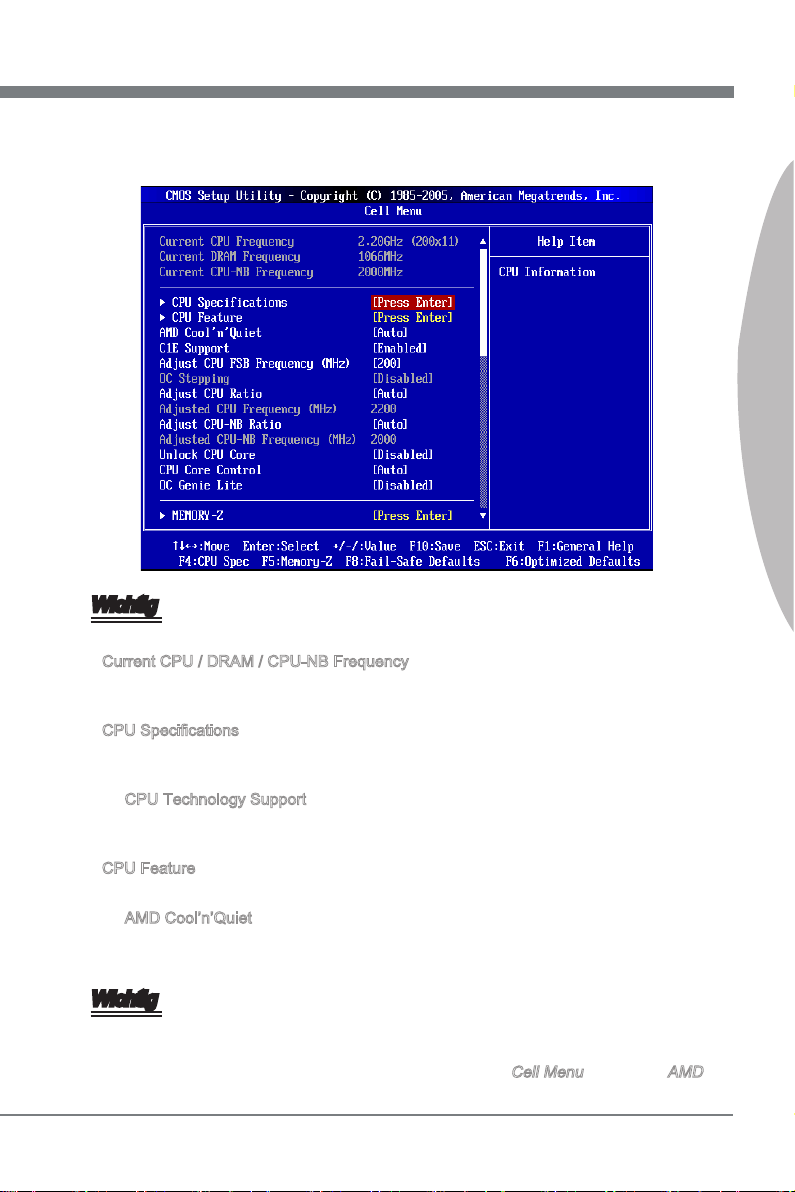
Deutsch
Cell Menu Introduction: Das Menü ist für den weiteren Benutzer, der die Haupt-
4.
platine übertakten mögen.
Wichtig
Nur wenn Sie mit dem Chipsatz vertraut sind, können Sie die Einstellung ändern.
Current CPU / DRAM / CPU-NB Frequency
▶
Zeigt die derzeitige Frequenz der CPU/ des Speichers & die Geschwindigkeit des CPU-
NBs. Nur Anzeige.
CPU Specications
▶
Press <Enter> to enter the sub-menu. This submenu shows the information of installed
CPU.
CPU Technology Support
▶
Drücken Sie die Eingabetaste <Enter>, um das Untermenü aufzurufen. Das Unter-
menü zeigt die Technologien des installierten CPUs.
CPU Feature
▶
Drücken Sie die Eingabetaste <Enter>, um das Untermenü aufzurufen.
AMD Cool’n’Quiet
▶
Die Cool’n’Quiet-Technologie kann die CPU-Geschwindigkeit und den Stromver-
brauch ezient und dynamisch herabsetzen.
Deutsch
Wichtig
Für eine einwandfreie Funktion von Cool’n’Quiet muss folgende Vorgehensweise unbedingt sichergestellt werden:
BIOS Setup ausführen und wählen Cell Menu aus Unter Cell Menu setzen Sie AMD
•
De-33

MS-7660 Mainboard
Deutsch
Cool’n’Quiet, auf “Enabled”.
Önen Sie Windows und wählen Sie [Start] -> [Ein tellungen] -> [Systemsteuerung]
•
-> [Energieoptionen]. Gehen Sie zu Eigenschaften von Energieoptionen (Power Options Properties), und wählen Sie Minimaler Energieverbrauch (Minimal Power Management) under Energieschemas (Power schemes).
C1E Support
▶
Während des Leerlaufs aktiviert die Funktion, um die Stromaufnahme lesen. Nicht
alle Prozessor unterstützt Enhanced Halt Stand (C1E).
SVM Support
▶
Diese Option aktiviert oder deaktiviert das SVM.
AMD Cool’n’Quiet
▶
Die Cool’n’Quiet-Technologie kann die CPU-Geschwindigkeit und den Stromverbrauch
ezient und dynamisch herabsetzen.
C1E Support
▶
Während des Leerlaufs aktiviert die Funktion, um die Stromaufnahme lesen. Nicht alle
Prozessor unterstützt Enhanced Halt Stand (C1E).
Adjust CPU FSB Frequency (MHz)
▶
Hier können Sie die CPU FSB Frequenz verändern (in MHz).
OC Stepping
▶
OC Stepping ist aktiviert, nachdem Sie die Frenquenz der Übertaktung im “Adjust CPU
FSB Frequency (MHz)” einstellt. Die folgenden Einzelteile erscheinen und das System
kann Schritt für Schritt übertaken nach System Laden des Betriebssystems oben.
Start OC Stepping From (MHz)
▶
Hier kann den Angangs-FSB-Takt angeben. Das system bootet mit dem Angangs-
FSB-Takt, und übertakt vom Angangs-FSB-Takt zu eingestellten FSB-Takt, die im
“Adjust CPU FSB Frequency (MHz)” Schritt für Schritt einsetzen.
OC Step
▶
Stellt wieviele Schritte für das niedrige FSB-Takt Übertaktung ein.
OC Step Count Timer
▶
Stellt die Puerzeit für jeden Schritt ein.
Adjust CPU Ratio
▶
Hier können Sie die CPU-Taktmultiplikator (Ratio) angeben. Dies können Sie nur
benutzen, wenn der Prozessor die Funktion unterstützt.
Adjusted CPU Frequency (MHz)
▶
Zeigt die verstellte Frequenz der CPU. Nur Anzeige.
Adjust CPU-NB Ratio
▶
Hier können Sie die CPU-NB-Taktmultiplikator (Ratio) angeben.
Adjusted CPU-NB Frequency (MHz)
▶
Zeigt die verstellte Frequenz der CPU-NB. Nur Anzeige.
De-34

Deutsch
Unlock CPU Core
▶
Hier können Sie den CPU-Kern freischalten. Bitte beachten Sie dazu die nachfolgend
beschriebenen Verfahren beziehen, um die CPU-Kern im BIOS-Setup freizuschalten.
Geben Sie “Cell Menu” und setzen Sie “Unlock CPU Core”
auf [Enabled].
Speichern Sie die Änderungen und verlassen Sie das BIOS-Setup.
System neustarten.
Erfolg
Sehen Sie die “X4” (Quad Core) oder “X2” (Dual-Core nur
für Sempron-Serie) während des POST.
AMD Phenom(tm) II X4 Prozessor
AMD Sempron(tm) II X2 Prozessor
Fehler
Setzen Sie “Adjust CPU-NB Ratio”
und “HT Link Speed” auf [x8].
Löschen Sie das CMOS Daten.
Die CPU unterstützt nicht Freischalten
von CPU-Kern, bitte lassen Sie die Standardeinstellungen für das System.
Wichtig
Diese CPU-Kern freigeschaltet Verhalten hängt von der Fähigkeit / Eigenschaft CPU,
•
und es ist nicht garantiert.
Hängen Sie von der Eigenschaft CPU, sobald Sie instabil Szenario erhalten, bitte
•
wieder die Standardeinstellungen für die System.
Sie können die Kernzahlen in die Registerkarte Leistung des Windows Task-Man-
•
ager prüfen.
CPU Core Control
▶
Hier können Sie die Zahl der aktiven Prozessorkernen vorwählen.
OC Genie Lite
▶
Die Einstellung [Enabled] erlaubt das System, maximaler FSB-Takt zu erkennen und
automatish zu übertakten. Wenn die Übertaktung nicht ausgeführt werden kann, können Sie bei niedriger FSB-Takt für erfolgreiche Übertaktung versuchen.
MEMORY-Z
▶
Drücken Sie die Eingabetaste <Enter>, um das Untermenü aufzurufen.
DIMM1~4 Memory SPD Information
▶
Drücken Sie die Eingabetaste <Enter>, um das Untermenü aufzurufen. Das Unter-
menü zeigt die Informationen des installierten Speichers an.
Deutsch
De-35

MS-7660 Mainboard
Deutsch
Advance DRAM Conguration
▶
Drücken Sie die Eingabetaste <Enter>, um das Untermenü aufzurufen.
DRAM Timing Mode
▶
Dieses kann alles DRAM Timing automatisch auangen.
1T/2T Memory Timing
▶
Legt die SDRAM Kommandorate fest. Die Einstellung [1T] lässt den SDRAM Signal
Kontroller mit einem 1T (Taktzyklus) laufen. Bei [2T] läuft er mit zwei Zyklen.
DCT Unganged Mode
▶
Im Unganged Modus, ein logisches DIMM irgendein ein 128-Bit DIMM.
Bank Interleaving
▶
Bank Interleaving ist ein wichtiger Parameter für das Verbessern von Übertaktung
Fähigkeit des Speichers. Es lässt System mehrfache Bänke gleichzeitig zugänglich
machen.
Power Down Enable
▶
Es ist eine energiesparende Technologie des Speicher. Wenn das System nicht auf
den Speicher uber einen Zeitraum von Zeit zugreift, verringert es automatisch die
Stromversorgung des Speichers.
MemClk Tristate C3/ATLVID
▶
Diese Einstellung erlaubt Ihnen, das MemClk Tristating wahrend C3 und ATLVID
zu aktivieren/ deaktivieren.
FSB/DRAM Ratio
▶
Können Sie hier den FSB/Speicher des Ratios anpassen.
Adjusted DRAM Frequency (MHz)
▶
Gibt der verstellt Frequenz des DDR Speicher. Nur Anzeige.
HT Link Control
▶
Drücken Sie die Eingabetaste <Enter>, um das Untermenü aufzurufen.
HT Incoming/ Outgoing Link Width
▶
Setzt die Bandbreite des Hyper-Transport Links fest. Mit der Einstellung [Auto],
erkennt das System die HT Link Bandbreite automatisch.
HT Link Speed
▶
Gibt die Betriebsfrequenz des Taktgebers des Hypertransport Links vor. Mit der Einstel-
lung [Auto], erkennt das System die HT Link Geschwindigkeit automatisch.
Adjusted HT Link Frequency (MHz)
▶
Gibt der verstellt Frequenz des HT-Links. Nur Anzeige.
Adjust PCI-E Frequency (MHz)
▶
Gestattet die Wahl der PCI-E Frequenz (in MHz).
De-36

Deutsch
Auto Disable DRAM/PCI Frequency
▶
Lautet die Einstellung auf [Enabled] (eingeschaltet), deaktiviert das System die Taktung
leerer PCI Sockel, um die Elektromagnetische Störstrahlung (EMI) zu minimieren.
CPU VDD Voltage (V)/ CPU-NB VDD Voltage (V)/ CPU Voltage (V)/ CPU-NB Voltage
▶
(V)/ CPU PLL Voltage (V)/ CPU DDR-PHY Voltage (V)/ DRAM Voltage (V)/ DDR VTT
Voltage (V)/ NB Voltage (V)/ NB PCI-E Voltage (V)/ SB Voltage (V)/ HT Link Voltage
(V)
Diese Option bietet Ihnen an, die Spannung des CPU, des Speichers und des Chipsatz
anzupassen.
Spread Spectrum
▶
Pulsiert der Taktgenerator des Motherboards, erzeugen die Extremwerte (Spitzen) der
Pulse EMI (Elektromagnetische Interferenzen). Die Spread Spectrum Funktion reduziert die erzeugten EMI, indem die Pulse so moduliert werden, das die Pulsspitzen zu
acheren Kurven reduziert werden.
Wichtig
Sollten Sie keine Probleme mit Interferenzen haben, belassen Sie es bei der Einstel-
•
lung [Disabled] (ausgeschaltet) , um bestmögliche Systemstabilität und -leistung zu
gewährleisten. Stellt für sie EMI ein Problem dar, wählen Sie die gewünschte Bandbreite zur Reduktion der EMI.
Je größer Spread Spectrum Wert ist, desto größer nimmt der EMI ab, und das Sys-
•
tem wird weniger stabil. Bitte befragen Sie Ihren lokalen EMI Regelung zum meist
passend Spread Spectrum Wert.
Denken Sie daran Spread Spectrum zu deaktivieren, wenn Sie übertakten, da sogar
•
eine leichte Schwankung eine vorübergehende Taktsteigerung erzeugen kann, die
gerade ausreichen mag, um Ihren übertakteten Prozessor zum einfrieren zu bringen.
Deutsch
De-37

MS-7660 Mainboard
Software-Information
Die im Mainboard-Paket enthaltene DVD enthält alle notwendigen Treiber. Um die
Installation automatisch laufen zu lassen, klicken Sie einfach den Treiber oder Utiltiy
und folgen Sie dem Pop-Up Schirm, um die Installation durchzuführen. Der Treibergebrauchs-DVD enthält:
Treibermenü - das Treibermenü zeigt die vorhandenen Treiber. Aktivieren Sie den
gewünschten Treiber.
Gebrauchsmenü - das Gebrauchsmenü zeigt die Software-Anwendungen der die
Mainboard Unterstützungen.
Wichtig
Besuchen Sie bitte die MSI Website, um die neuesten Treiber und BIOS für bessere
System Leistung zu erhalten.
De-38

Français
870A Fuzion
Power Edition Séries
Europe version

Carte mère MS-7660
Spécications
Processeurs Supportés
AMD® PhenomTM II séries, AthlonTM II séries et SempronTM séries processeurs dans
■
le paquet AM3.
(Pour plus d’information sur le CPU, veuillez visiter http://www.msi.com/index.
php?func=cpuform2)
HyperTransport
HyperTransport™ 3.0, supporte jusqu’à 5.2 GT/s
■
Jeu de puces
North Bridge : puce AMD® RX780
■
South Bridge : puce AMD® SB850/ SB810
■
Lucid® LT22102
■
Mémoire supportée
DDR3 1600 *(OC)/ 1333/ 1066 DRAM (total 16GB Max)
■
4 DDR3 DIMMs, supporte le double-canaux
■
*(Pour plus d’information sur les composants compatible, veuillez visiter
http://www.msi.com/index.php?func=testreport)
LAN
Supporte PCIE LAN (10/100/1000) par Realtek® RTL8111DL
■
IEEE 1394
Puce intégrée par VIA® VT6315N
■
Supporte 1 port IEEE 1394 (panneau arrière) et 1 connecteur IEEE 1394
■
Audio
HD audio codec intégré par Realtek® ALC892/ ALC889
■
8-canaux audio exibles avec détection de prise
■
SATA
6 ports SATA 6Gb/s par AMD® SB850
■
Ou 6 ports SATA 3Gb/s par AMD® SB810
■
Supporte la déconnection à chaud et la notication asynchrone
■
USB 3.0
2 ports USB 3.0 par NEC uPD720200F1
■
RAID
SATA1~6 ports supportent le mode RAID 0/ 1/ 5/ 10 par AMD® SB850
■
Ou SATA1~6 ports supportent le mode RAID 0/ 1/ 10 par AMD® SB810
■
Fr-2

Connecteurs
Panneau arrière
■
1 port clavier PS/2
1 port souris PS/2
1 bouton d’eacement CMOS
1 port coaxial S/PDIF-Out
1 port optique S/PDIF-Out
6 ports USB 2.0
1 port USB 3.0
1 port IEEE 1394
1 port LAN
6 ports audio exibles
-
Connecteurs intégrés
■
3 connecteurs USB 2.0
1 connecteur USB 3.0
1 connecteur IEEE 1394
1 connecteur Châssis Intrusion
1 connecteur S/PDIF-Out
1 connecteur audio avant
1 connecteur de port sérial
1 connecteur du Module TPM
1 bouton d’alimentation
1 bouton réinitialisation
1 bouton Green Power
1 bouton OC Genie
-
Emplacments
2 emplacements PCIE x16
■
Supporte la technologie informatique Multi-GPU
Supporte la technologie ATI CrossFireX
-
3 emplacements PCIE x1
■
1 emplacement PCI, supporte l’Interface bus PCI 3.3V/ 5V
■
TM
Dimension
ATX (24.5cm X 30.5 cm)
■
Montage
9 trous de montage
■
Français
* Si vous désirez acheter des accessoires et vous avez besoin de numéros des pièces,
vous pouvez chercher sur la page website et trouver les détails sur notre adresse cidessous http://www.msi.com/index.php
Fr-3

Carte mère MS-7660
RESET
Green
Power
Guide Rapide Des Composants
Panneau
arrière,
Fr-13
USB5, Fr-18
PCIE, Fr-24
JCI1, Fr-15
PCI, Fr-25
JCD1, Fr-18
JAUD1, Fr-16
JPWR3, Fr-12
JPWR2, Fr-11
JSP1, Fr-17
SYSFAN2/1, Fr-16
J1394_1, Fr-19
CPU, Fr-6
JUSB1~3, Fr-18
JBAT1, Fr-21
DDR3, Fr-9
CPUFAN, Fr-16
SYSFAN3, Fr-16
JPWR1, Fr-11
JTPM1, Fr-20
JFP1/ JFP2, Fr-17
SATA, Fr-15
POWER1, Fr-22
RESET1, Fr-22
GREEN1, Fr-22
OC Genie, Fr-23
JCOM1, Fr-19
Fr-4

RESET
Green
Power
Trous Taraudés
Quand vous installez la carte mère, il faut déposer la carte dans le châssis en bonne
position. La situation des trous taraudés sont montrée dans la gure ci-dessous.
Face vers l’arrière, position pour la protège Entré/ Sortie du châssis.
Français
Trous taraudés
Veuillez vous référer à la gure pour installer le support dans une position appropriée
sur le châssis et puis de xer la carte à travers les trous taraudés sur le support.
Important
Pour prévenir les endommages à la carte mère, il est interdit de mettre toute sorte de
•
contact entre le circuit et le châssis ou de mettre un support inutile sur le châssis.
Veuillez vous assurer qu’il n’y pas de composant en métal mis dans la carte ou le
•
châssis qui entraînerait un court circuit à la carte mère.
Fr-5

Carte mère MS-7660
Processeur : CPU
Quand vous installez le CPU, veuillez vous assurer d’installer un ventilateur pour éviter
la surchaue. Si vous n’en avez pas, contactez votre revendeu pour en acheter et installez-les avant d’allumer votre ordinateur.
Pour plus d’informations sur le CPU, veuillez visiter http://www.msi.com/index.
php?func=cpuform2
Important
Surchaue
La surchaue endommage sérieusement l’unité centrale et le système. Assurez-vous
toujours que le ventilateur de refroidissement fonctionne correctement pour protéger
l’unité centrale contre la surchaue. Assurez-vous d’appliquer une couche d’enduit
thermique (ou lm thermique) entre l’unité centrale et le dissipateur thermique pour
améliorer la dissipation de la chaleur.
Remplacement de l’unité centrale
Lorsque vous remplacez l’unité centrale, commencez toujours par couper l’alimentation
électrique de l’ATX ou par débrancher le cordon d’alimentation de la prise mise à la
terre pour garantir la sécurité de l’unité centrale.
Overclocking
Cette carte mère supporte l’overclocking. Néanmoins, veuillez vous assurer que vos
composants soient capables de tolérer ces congurations anormales, lors d’overclocking.
Tout envie d’opérer au dessus des spécications du produit n’est pas recommandé.
Nous ne garantissons pas les dommages et risques causés par les opérations insufsantes ou au dessus des spécications du produit.
Introduction du AM3 CPU
La surface du CPU. N’oubliez pas d’appliquer une couche d’enduit thermique
pour améliorer la dissipation de la chaleur.
La èche d'or
Fr-6

Installation du CPU et son ventilateur
Quand vous installez le CPU, assurez-vous que le CPU soit équipé d’un ventilateur de
refroidissement attaché sur le dessus pour éviter la surchaue. Méanmoins, n’oubliez
pas d’appliquer une couche d’enduit thermique sur le CPU avant d’installer le ventilateur pour une meilleure dissipation de chaleur.
Suivez les instruction suivantes pour installer le CPU et son ventilateur correctement.
une faute installation peut endommager votre CPU et la carte mère.
Enlevez le levier de côté de la dou-
1.
ille et assurez-vous de lever le levier
jusqu’à 90 degrés.
Si le CPU est correctement installé,
3. Appuyez sur le CPU fermement dans
les pins doivent s’intégrer complètement dans la douille et sont
invisibles. Veuillez noter que toute
violence ou une fausse installation
peut endommager votre carte mère
en permanance.
Trouvez la èche d’or du CPU et
2.
mettez-la comme montré dans
l’image. Le CPU ne s’installe que
dans la position correcte.
4.
la douille et fermez le levier. Puisque
le CPU a une tendance de bouger
lors de la fermeture du levier, il faut
fermer le levier en appuyant sur le
CPU pour qu’il soit complètement et
correctement installé dans la douille.
Français
Fr-7

Carte mère MS-7660
Déposez l’ensemble du ventilateur
5. Puis appuyez sur l’autre côté du clip
sur le mécanisme de rétention.
Accrochez un côté du clip d’abord.
6.
pour xer l’ensemble du ventilateur
sur le mécanisme de rétention.
Localisez le levier de xe et levez-le.
Fixez le levier.7. Attachez le câble du ventilateur
8.
de CPU au connecteur sur la carte
mère.
Important
Les photos de la carte mère montrées dans cette partie ne sont que pour une dé-
•
monstration. L’apparence de votre carte mère peut varier selon le modèle que vous
achetez.
Quand vous déconnectez le Crochet de Sécurité du verrou xé, il faut garder un oeil
•
sur vos doigts, parce qu’une fois le Crochet de Sécurité est déconnecté du verrou, le
levier xé jaillira immédiatement.
Fr-8

Mémoire
Ces slots DIMM sont destinés à installer les modules de mémoire. Pour plus
d’informations sur les composants compatibles, veuillez visiter
dex.php?func=testreport
DDR3
240-pin, 1.5V
Règle de population en mode double-canaux
En mode de canaux-double, les modules de mémoire peuvent transmettre et recevoir
les données avec simultanément deux lignes omnibus de données. L’activation du
mode de canaux-double peut améliorer les performances du système. Veuillez vous
reporter aux illustrations suivantes pour connaître les règles de population en mode de
canaux-double.
http://www.msi.com/in-
48x2=96 pin 72x2=144 pin
Français
DIMM2
DIMM3
DIMM4
1
DIMM1
2
DIMM1
DIMM2
DIMM3
DIMM4
Installé
Vide
Important
Les modules de mémoire DDR3 ne sont pas interchangeables par DDR2 et vice
•
versa. Vous devez toujours installer les modules de mémoire DDR3 dans les slots
DDR3 DIMM.
En mode double canaux, assurez-vous que vous installez les modules de mémoire
•
du même type et de la même densité dans les slots DIMM de canaux différents
Pour lancer avec succès votre système, insérez tout d’abord les modules de mé-
•
moire dans le DIMM1
A cause du développement de la ressource du chipset, la densité du système sera
•
détecté seulement jusqu’à 15+GB (non 16GB plein) quand chaque DIMM est installé
avec un module de mémoire de 4GB.
.
.
Fr-9

Carte mère MS-7660
Installation des modules de mémoire
Le module de mémoire possède une seule encoche en son centre et ne s’adaptera
1.
que s’il est orienté de la mqnière convenable.
Insérez le module de mémoire à la verticale dans le slot du DIMM. Poussez-le en-
2.
suite jusqu’à l’extrémité dorée du module de mémoire, soit profondément insérée
dans le slot du DIMM. Les clips en plastique situés de chaque côté du module va
se fermer automatiquement.
Vériez manuellement si la barrette mémoire a été verrouillée en place par les clips
3.
du slot DIMM sur les côtés.
Encoche
Volt
Important
Vous pourriez à peine voir l’extrémité dorée si le module de mémoire est correctement
inséré dans le slot du DIMM.
Fr-10

Connecteurs d’alimentation
13 .+3 .3
V
1. +3. 3
V
14 .-1 2V
2. +3. 3
V
15 .Gr oun d
3
.G rou nd
16 .PS -ON
#
4. +5
V
17 .Gr oun d
5
.G rou nd
18 .Gr oun d
6. +5
V
19 .Gr oun d
7
.G rou nd
22 .+5
V
10 .+1 2V
20 .Re s
8. PW
R O
K
23 .+5
V
11
.+ 12V
21 .+5
V
9. 5VS B
24 .Gr oun d
12 .+3 .3
V
7. +12 V
3.
Gr oun d
5. +12 V
1.
Gr oun d
8. +12 V
4
.G rou nd
6. +12 V
2
.G rou nd
Connecteur d’alimentation ATX 24-pin : JPWR1
Ce connecteur vous permet de connecter l’alimentation ATX 24-pin. Pour cela, assurez-vous que la prise d’alimentation est bien positionnée dans le bon sens et que les
goupilles soient alignées. Enfoncez alors la prise dans le connecteur.
Vous pourvez aussi utiliser un alimentation 20-pin selon vos besoins. Veuillez brancher
votre alimentation d’énergie avec le pin 1 et le pin 13 si vous voulez utiliser l’alimentation
ATX 20-pin.
Connecteur d’alimentation ATX 8-pin : JPWR2
Ce connecteur d’alimentation sert à fournir de l’alimentation de 12V au CPU.
Français
Fr-11

Carte mère MS-7660
Connecteur d’alimentation ATX 6-pin : JPWR3
Ce connecteur d’alimentation sert à fournir de l’alimentation à la carte graphics.
Important
Veuillez vous assurer que tous les connecteurs sont connectés aux correctes alimen-
•
tations ATX pour garantir une opération stable de la carte mère.
Fr-12

Panneau arrière
Souris
Bouton
d'eacement
CMOS
Clavier
Souris/Clavier
▶
S/PDIF-Out
coaxial
S/PDIF-Out
optique
Port USB 2.0
Port IEEE 1394
Port USB 2.0
LAN
Port USB 2.0
Port USB 3.0
Ligne-In
Ligne-Out
Mic
RS-Out
CS-Out
SS-Out
Le standard connecteur de souris/clavier DIN de PS/2® est pour une souris ou un clavier
de PS/2® .
Bouton d’eacement CMOS
▶
Il y a un CMOS RAM intégré, qui possède un bloc d’alimentation alimenté par une bat-
terie externe, destiné à conserver les données de conguration du système. Avec le
CMOS RAM, le système peut lancer automatiquement le système d’exploitation chaque
fois qu’il est allumé. Si vous souhaitez eacer la conguration du système, utilisez ce
bouton pour eacer les données. Appuyez le bouton pour eacer les données.
Important
Veuillez vous assurer d’éteindre le système avant d’eacer les données CMOS.
Après avoir appuyé ce bouton pour eacer les données CMOS au statut éteint (G3), le
système se réinitialise automatiquement.
S/PDIF-Out coaxial
▶
Ce connecteur est utilisé pour relier l’interface S/PDIF (Sony et Philips Digital Intercon-
nect Format) de la transmission audio numérique à un haut-parleur externe via un câble
coaxial.
Français
S/PDIF-Out optique
▶
Ce connecteur est utilisé pour relier l’interface S/PDIF (Sony et Philips Digital Intercon-
nect Format) de la transmission audio numérique à un haut-parleur externe via un câble
de bre optique.
Port USB 2.0
▶
Le port USB (Universal Serial Bus) sert à brancher des périphériques USB tels que le
clavier, la souris, ou d’autres périphériques compatibles USB. Supporte la trasmission
de données jusqu’à 480Mbit/s (Hi-Speed).
Fr-13

Carte mère MS-7660
Port IEEE 1394
▶
Le port IEEE1394 sur le panneau arrière fournit une connexion aux périphériques
IEEE1394.
Port USB 3.0
▶
Le port USB 3.0 est inférieur-compatible avec les périphériques USB 2.0. Il supporte le
taux de transfert jusqu'à 5 Gbit/s (Super-Vitesse).
Important
Si vous voulez appliquer un périphérique USB 3.0, il faut utiliser une câble USB 3.0
pour connecter au port USB 3.0.
LAN
▶
La prise standard RJ-45 LAN sert à la connexion
au réseau local (Local Area Network (LAN)). Vous
pouvez y relier un câble de réseau.
LED Couleur LED Statut Condition
Gauche Jaune Eteinte La connexion au réseau LAN n’est pas établie.
Allumée (Stable) La connexion au réseau LAN est établie.
Allumée (plus brillant
et clignotante)
Droite Vert Eteinte Un débit de 10 Mbits/sec est sélectionné.
Allumée Un débit de 100 Mbits/sec est sélectionné.
Orange Allumée Un débit de 1000 Mbits/sec est sélectionné.
L’ordinateur communique avec un autre ordinateur sur le réseau
local LAN.
Jaune Vert/ Orange
Ports Audio
▶
Ces connecteurs audio servent pour les périphériques audio. Vous pouvez diérencier
la couleur des prises audio pour obtenir divers eets sonores.
Ligne-In (Bleu) - Ligne In, est utilisée pour un appareil de CD externe, cassette
■
ou d’autre périphériques.
Ligne-Out (Vert) - Ligne Out, est destiné aux haut-parleurs ou aux casques
■
d’écoute.
Mic (Rose) - Mic, est un connecteur pour les microphones.
■
RS-Out (Noir) - Rear-Surround Out en mode de canal 4/ 5.1/ 7.1.
■
CS-Out (Orange) - Center/ Subwoofer Out en mode de canal 5.1/ 7.1.
■
SS-Out (Gris) - Side-Surround Out en mode de canal 7.1.
■
Fr-14
 Loading...