


K8MM3 Series
MS-7181 (v2.X) Micro-ATX Mainboard
G52-M7181X4
i
FCC-B Radio Frequency Interference Statement
This equipment has been tested and found to comply with the limits for a class B digital device, pursuant to part 15 of the FCC rules. These limits are designed
to provide reasonable protection against harmful interference in a residential installation. This equipment generates, uses and can radiate radio frequency energy and, if not installed and used in accordance with the instruction manual, may cause harmful interference to radio communications. However, there is no guarantee that interference will not occur in a particular installation. If this equipment does cause harmful interference to radio or television reception, which can be determined by turning the equipment off and on, the user is encouraged to try to correct the interference by one or more of the measures listed below.
=Reorient or relocate the receiving antenna.
=Increase the separation between the equipment and receiver.
=Connect the equipment into an outlet on a circuit different from that to which the receiver is connected.
=Consult the dealer or an experienced radio/television technician for help.
Notice 1
The changes or modifications not expressly approved by the party responsible for compliance could void the user’s authority to operate the equipment.
Notice 2
Shielded interface cables and A.C. power cord, if any, must be used in order to comply with the emission limits.
VOIR LA NOTICE D’INSTALLATION AVANT DE RACCORDER AU RESEAU.
Micro-StarInternational
MS-7181
This device complies with Part 15 of the FCC Rules. Operation is subject to the following two conditions:
(1)this device may not cause harmful interference, and
(2)this device must accept any interference received, including interference that may cause undesired operation
ii

Copyright Notice
The material in this document is the intellectual property of M ICRO-STAR INTERNATIONAL. We take every care in the preparation of this document, but no guarantee is given as to the correctness of its contents. Our products are under continual improvement and we reserve the right to make changes without notice.
Trademarks
All trademarks are the properties of their respective owners.
AMD, Athlon™64 and Athlon™ FX are registered trademarks of AMD Corporation. Intel® and Pentium® are registered trademarks of Intel Corporation.
PS/2 and OS®/2 are registered trademarks of International Business Machines Corporation.
Microsoft is a registered trademark of Microsoft Corporation. Windows® 98/2000/NT/ XP are registered trademarks of Microsoft Corporation.
NVIDIA, the NVIDIA logo, DualNet, and nForce are registered trademarks or trademarks of NVIDIA Corporation in the United States and/or other countries.
Netware® is a registered trademark of Novell, Inc.
Award® is a registered trademark of Phoenix Technologies Ltd. AMI® is a registered trademark of American Megatrends Inc.
Kensington and MicroSaver are registered trademarks of the Kensington Technology Group.
PCMCIA and CardBus are registered trademarks of the Personal Computer Memory Card International Association.
Revision History
Revision |
Revision History |
Date |
V1.0 |
First release for PCB 1.X |
May 2005 |
|
with VIA K8M800 & VT8237R |
|
V1.1 |
Add WEEE Statement |
Sept. 2005 |
|
with VIA K8M800 & VT8237R/ VT8237R Plus |
|
V2.0 |
First release for PCB 2.X |
January 2006 |
|
with VIA K8M800 & VT8237R/ VT8237R Plus |
|
iii

Technical Support
If a problem arises with your system and no solution can be obtained from the user’s manual, please contact your place of purchase or local distributor. Alternatively, please try the following help resources for further guidance.
† Visit the MSI homepage & FAQ site for technical guide, BIOS updates, driver updates, and other information: http://www.msi.com.tw & http://www.msi. com.tw/program/service/faq/faq/esc_faq_list.php
† Contact our technical staff at: support@msi.com.tw
Safety Instructions
1.Always read the safety instructions carefully.
2.Keep this User’s Manual for future reference.
3.Keep this equipment away from humidity.
4.Lay this equipment on a reliable flat surface before setting it up.
5.The openings on the enclosure are for air convection hence protects the equipment from overheating. Do not cover the openings.
6.Make sure the voltage of the power source and adjust properly 110/220V before connecting the equipment to the power inlet.
7.Place the power cord such a way that people can not step on it. Do not place anything over the power cord.
8.Always Unplug the Power Cord before inserting any add-on card or module.
9.All cautions and warnings on the equipment should be noted.
10.Never pour any liquid into the opening that could damage or cause electrical shock.
11.If any of the following situations arises, get the equipment checked by a service personnel:
†The power cord or plug is damaged.
†Liquid has penetrated into the equipment.
†The equipment has been exposed to moisture.
†The equipment has not work well or you can not get it work according to User’s Manual.
†The equipment has dropped and damaged.
†The equipment has obvious sign of breakage.
12.Do not leave this equipment in an environment unconditioned, storage
temperature above 600 C (1400F), it may damage the equipment.
CAUTION: Danger of explosion if battery is incorrectly replaced. Replace only with the same or equivalent type recommended by the manufacturer.
iv

WEEE Statement
v

vi

vii
CONTENTS
FCC-B Radio Frequency Interference Statement .......................................................... |
ii |
Copyright Notice .............................................................................................................. |
iii |
Revision History .............................................................................................................. |
iii |
Technical Support .......................................................................................................... |
iv |
Safety Instructions ......................................................................................................... |
iv |
WEEE Statement........................................................................................................ |
v |
Chapter 1. Getting Started .................................................................................... |
1-1 |
Mainboard Specifications ................................................................................... |
1-2 |
Mainboard Layout ................................................................................................ |
1-4 |
Packing Contents ................................................................................................. |
1-5 |
Chapter 2. Hardware Setup .................................................................................. |
2-1 |
Quick Components Guide ................................................................................... |
2-2 |
Central Processing Unit: CPU ............................................................................. |
2-3 |
Memory Speed/CPU FSB Support Matrix................................................... |
2-3 |
CPU Installation Procedures for Socket 754 ............................................. |
2-4 |
Installing AMD Athlon64 CPU Cooler Set .................................................... |
2-5 |
Memory................................................................................................................. |
2-6 |
Introduction to DDR SDRAM ....................................................................... |
2-6 |
DDR DIMM Module Combination .................................................................. |
2-7 |
Installing DDR Modules ................................................................................ |
2-7 |
Power Supply ...................................................................................................... |
2-8 |
ATX 20-Pin Power Connector: JWR1 ........................................................ |
2-8 |
ATX 12V Power Connector: JPW1 ............................................................ |
2-8 |
Back Panel ........................................................................................................... |
2-9 |
View of the Back Panel .............................................................................. |
2-9 |
Serial Port: COM1 ........................................................................................ |
2-9 |
Mouse Connector ...................................................................................... |
2-10 |
Keyboard Connector ................................................................................. |
2-10 |
VGA Connector ......................................................................................... |
2-10 |
USB Ports .................................................................................................... |
2-11 |
RJ-45 LAN Jack .......................................................................................... |
2-11 |
IEEE 1394 Port ............................................................................................ |
2-12 |
Audio Port Connectors .............................................................................. |
2-12 |
Parallel Port ................................................................................................ |
2-13 |
Connectors ........................................................................................................ |
2-14 |
Floppy Disk Drive Connector: FDD1 ........................................................ |
2-14 |
viii
Fan Power Connectors: CPUFAN1, SFAN1 ............................................ |
2-14 |
Hard Disk Connectors: IDE1 & IDE2 ......................................................... |
2-15 |
Serial Port Header: JCOM1 (Optional) ..................................................... |
2-15 |
Serial ATA/Serial ATA RAID Connectors controlled by VT8237R/VT8237R |
|
Plus: SATA1 & SATA2 ............................................................................... |
2-16 |
Front Panel Connectors: JFP1 & JFP2 ..................................................... |
2-17 |
Chassis Intrusion Switch Connector: JCI1 .............................................. |
2-17 |
Aux Line-In Connector: JAUX1 ................................................................ |
2-18 |
CD-In Connector: JCD1 ............................................................................. |
2-18 |
Front USB Connectors: JUSB1 & JUSB2 ................................................. |
2-18 |
Front Panel Audio Connector: JAUD1 ...................................................... |
2-19 |
IrDA Infrared Module Header: JIR1 ........................................................... |
2-19 |
IEEE 1394 Connector: J1394_1 ................................................................ |
2-20 |
SPDIF-Out Connector: JSP1 ..................................................................... |
2-20 |
Jumpers .............................................................................................................. |
2-21 |
Clear CMOS Jumper: JBAT1 ..................................................................... |
2-21 |
Slots .................................................................................................................... |
2-22 |
AGP (Accelerated Graphics Port) Slot .................................................... |
2-22 |
PCI (Peripheral Component Interconnect) Slots ...................................... |
2-22 |
PCI Interrupt Request Routing ................................................................... |
2-22 |
Chapter 3. BIOS Setup ............................................................................................ |
3-1 |
Entering Setup ..................................................................................................... |
3-2 |
Selecting the First Boot Device .................................................................. |
3-2 |
Control Keys ................................................................................................ |
3-3 |
Getting Help .................................................................................................. |
3-3 |
The Main Menu ..................................................................................................... |
3-4 |
Standard CMOS Features ................................................................................... |
3-6 |
Advanced BIOS Features ................................................................................... |
3-8 |
Advanced Chipset Features ............................................................................ |
3-10 |
Integrated Peripherals ....................................................................................... |
3-14 |
Power Management Setup ............................................................................... |
3-17 |
PNP/PCI Configurations ..................................................................................... |
3-20 |
H/W Monitor ........................................................................................................ |
3-22 |
Load Optimized Defaults ................................................................................... |
3-24 |
BIOS Setting Password .................................................................................... |
3-25 |
Chapter 4. Introduction to DigiCell ..................................................................... |
4-1 |
Main ...................................................................................................................... |
4-2 |
Introduction: ................................................................................................. |
4-2 |
ix
H/W Diagnostic .................................................................................................... |
4-4 |
Communication ..................................................................................................... |
4-5 |
Software Access Point ....................................................................................... |
4-6 |
Terminology .................................................................................................. |
4-6 |
Access Point Mode ..................................................................................... |
4-7 |
WLAN Card Mode ........................................................................................ |
4-8 |
Live Update .......................................................................................................... |
4-9 |
MEGA STICK ....................................................................................................... |
4-10 |
Basic Function ........................................................................................... |
4-10 |
Non-Unicode programs supported ........................................................... |
4-12 |
PC Alert ............................................................................................................... |
4-14 |
Audio Speaker Setting ...................................................................................... |
4-15 |
Power on Agent ................................................................................................. |
4-17 |
Power On ................................................................................................... |
4-17 |
Power Off / Restart ................................................................................... |
4-18 |
Start With .................................................................................................... |
4-18 |
Auto Login .................................................................................................. |
4-19 |
Chapter 5. VIA VT8237R/ VT8237R Plus SATA RAID Introduction ................ |
5-1 |
Introduction .......................................................................................................... |
5-2 |
RAID Basics ................................................................................................. |
5-2 |
RAID 0 (Striping) .......................................................................................... |
5-2 |
RAID 1 (Mirroring) ........................................................................................ |
5-2 |
BIOS Configuration .............................................................................................. |
5-3 |
Create Disk Array ........................................................................................ |
5-4 |
Delete Disk Array ......................................................................................... |
5-6 |
Create and Delete Spare Hard Drive ......................................................... |
5-7 |
View Serial Number of Hard Drive............................................................. |
5-7 |
Duplicate Critical RAID 1 Array ................................................................... |
5-8 |
Rebuild Broken RAID 1 Array ..................................................................... |
5-8 |
Installing RAID Software & Drivers ................................................................. |
5-10 |
Install Driver in Windows OS .................................................................... |
5-10 |
Installation of VIA SATA RAID Drvier and Utility ....................................... |
5-11 |
Using VIA RAID Tool .......................................................................................... |
5-13 |
Chapter 6. Using 2-, 4- & 6-Channel Audio Function ..................................... |
6-1 |
Installing the Audio Driver ................................................................................... |
6-2 |
Installation for Windows 98SE/ME/2000/XP .............................................. |
6-2 |
Special Notice during Installation ............................................................... |
6-2 |
x
Software Configuration ...................................................................................... |
6-4 |
Speaker ........................................................................................................ |
6-4 |
Mixer ............................................................................................................. |
6-5 |
Recording ..................................................................................................... |
6-5 |
SPDIF............................................................................................................. |
6-6 |
Speaker Test ................................................................................................ |
6-6 |
Information.................................................................................................... |
6-7 |
Using 2-, 4- & 6- Channel Audio Function ......................................................... |
6-8 |
xi

Getting Started
Getting Started
Thank you for purchasing the K8MM3 (MS-7181 v2.x) series, an excellent Micro-ATX mainboard from MSI. Based on the innovative VIA K8M800 and VIA VT8237R/ VT8237R Plus chipsets for optimal system efficiency, the K8MM3 serias mainboard accommodates latest AMD K8 processor in the 754-pin lidded ceramic micro PGA package, and supports up to 2 DIMMs to provide the maximum of 2 GB memory capacity. This mainboard provides a high professional desktop platform solution.
1- 1

MS-7181 Micro-ATX Mainboard
Mainboard Specifications
CPU
†Supports 64-bit AMD® K8 Athlon 64/ Sempron processor (Socket 754).
†Supports 3700+ or higher CPU.
Chipset
†VIA K8M800 Chipset
-HyperTransportTM connection to AMD K8 Athlon64/ Sempron processor -8 or 16 bit control/address/data transfer both directions -800/600/400/200 MHz “Double Data Rate” operation both direction -AGP v3.0 compliant with 8x transfer mode
-Graphic integrated
†VIA VT8237R/ VT8237R Plus Chipset
-Integrated Hardware Sound Blaster/Direct Sound AC97 audio
-Ultra DMA 66/100/133 master mode PCI EIDE controller
-ACPI& PC2001 compliant enhanced power management
-Supports dual channel native SATA controller up to 150MB/s
-Supports SATA RAID 0 or RAID 1
-Supports 8 USB2.0 ports
-Supports SATA2 Device (for VT8237R Plus only)
Main M emory
†Supports DDR266/333/400 DDR SDRAM, and unbuffered DIMMs for two 184pin DDR DIMMs.
†Supports DIMM sizes up to 2GB of memory in total.
Slots
†One AGP 8x/4x slot.
†Three 32-bit/33 MHz PCI slots.
On-Board IDE
†An IDE controller on the VT8237R/ VT8237R Plus chipset provides IDE HDD/CDROM with PIO, Bus Master and Ultra DMA133/100/66 operation modes.
-Can connect up to four Ultra ATA drives.
†Serial ATA/150 controller integrated in VT8237R/ VT8237R Plus.
-Up to 150MB/sec transfer speeds. (VT8237R Plus supports SATA2 device.)
-Can connect up to two Serial ATA drives.
-Supports RAID 0 or 1
1- 2

Getting Started
On-Board Peripherals
†On-Board Peripherals include:
-1 floppy port supports 1 FDDs with 360K, 720K, 1.2M, 1.44M and 2.88Mbytes
-2 serial ports (Rear * 1/ Front * 1)
-1 VGA port onboard
-1 parallel port supports SPP/EPP/ECP mode
-1 IrDA pinheader (optional)
-1 CD-In pinheader
-1 Aux-In pinheader
-1SPDIF out pinheader (optional)
-1 audio port (Line-in/Line-out/MIC)
-8 USB 1.1/2.0 ports (Rear * 4/ Front * 4)
IEEE 1394 (Optional)
†Supports up to 2 * 1394 ports (Rear * 1/ onboard header * 1). Transfer rate is up to 400Mbps
†Controlled by VIA 6307 or 6308P chipset
Audio
†AC’97 link controller integrated in VIA VT8237R/ VT8237R Plus.
†6 channels software audio codec VIA VT1617A
-Compliance with AC97 v2.3 Spec.
-Meet PC2001 audio performance requirement.
LAN
†VIA VT8237R/ VT8237R Plus MAC + VIA 6103 Ethernet PHY
-Supports 10/100Mb/s auto-negotiation operation.
-Compliant with PCI v2.2 and PC99 standard.
-Supports ACPI Power Management.
BIOS
†The mainboard BIOS provides “Plug & Play” BIOS which detects the peripheral devices and expansion cards of the board automatically.
†The mainboard provides a Desktop Management Interface (DMI) function which records your mainboard specifications.
Dimension and Mounting
†Micro-ATX Form Factor: 24.4 cm (L) x 21.5 cm (W).
†6 mounting holes
1- 3
MS-7181 Micro-ATX Mainboard
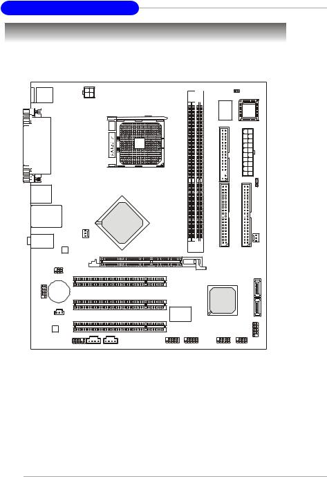
Mainboard Layout
Top : mouse |
|
|
|
|
DDR1 DDR2 |
|
JCI1 |
|
|
|
|
|
|
|
|
Bottom: keyboard |
JPW1 |
|
|
|
|
|
|
|
|
|
|
Winbond W83627EHG |
|
||
|
|
|
|
|
|
BIOS |
|
|
|
|
|
|
|
|
|
Top : |
|
|
|
|
|
|
|
Parallel Port |
|
|
|
|
|
|
|
Bottom: |
|
|
|
|
|
|
|
COM Port |
|
|
|
|
|
|
|
VGA Port |
|
|
|
|
|
FDD 1 |
|
|
|
|
|
|
|
JWR2 |
|
|
|
|
|
|
|
|
JBAT1 |
Top :1394 port |
|
|
|
|
|
|
|
B:USB ports |
|
|
|
|
|
|
|
Top: LAN Jack |
|
|
|
|
|
|
|
Bottom: USB |
|
|
VIA |
|
|
|
|
ports |
|
|
|
|
|
|
|
|
|
K8M800 |
|
|
1 |
2 |
|
|
|
|
|
|
|||
T:Line-In |
|
|
|
|
|
IDE |
IDE |
|
|
|
|
|
|
|
|
M:Line-Out |
CPUFAN1 |
|
|
|
|
|
|
B:Mic |
|
|
|
|
|
|
SFAN1 |
VIA |
|
|
|
|
|
|
|
VT6103L |
|
|
|
AGP 1 |
|
|
|
|
|
|
|
|
|
|
|
JIR1 |
PCI1 |
|
|
|
|
|
|
|
|
|
|
|
|
|
|
BATT |
|
|
|
|
|
|
SATA2 |
+ |
PCI2 |
|
|
|
|
VIA |
|
JCOM1 |
|
|
|
|
|
VT8237R/Plus |
|
(optional) |
|
|
|
|
|
|
SATA1 |
|
|
|
|
VIA |
|
|
|
JSP1 |
PCI3 |
|
|
VT6307/6308P |
|
||
|
|
|
|
|
|
||
|
|
|
|
|
|
|
|
VIA |
|
|
|
|
|
|
|
VT1617A |
|
|
|
|
|
|
|
|
|
|
|
|
|
|
JFP1 |
|
JAUD1 |
JCD1 |
JAUX1 |
J1394_1 |
JUSB2 |
JUSB1 |
JFP2 |
K8MM3 (MS-7181 v2.X) Series Mainboard |
|
||||||
1- 4
Getting Started
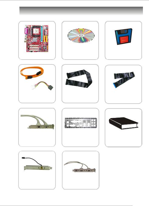
Packing Contents
MSI motherboard
SATA Cable/
Power Cable (Optional)
1394 Cable
(Optional)
SPDIF-Bracket
(Optional)
MSI Driver/Utility CD
Flat Cable of
Floppy Disk
Back IO Shield
USB Bracket
(Optional)
SATA RAID Driver
Diskette
Flat Cable of
IDE Devices
User’s Guide
* The pictures are for reference only and may vary from the packing contents of the product you purchased.
1- 5

Hardware Setup
Hardware Setup
This chapter provides you with the information about hardware setup procedures. While doing the installation, be careful in holding the components and follow the installation procedures. For some components, if you install in the wrong orientation, the components will not work properly.
Use a grounded wrist strap before handling computer components. Static electricity may damage the components.
2- 1
MS-7181 Micro-ATX M ainboard
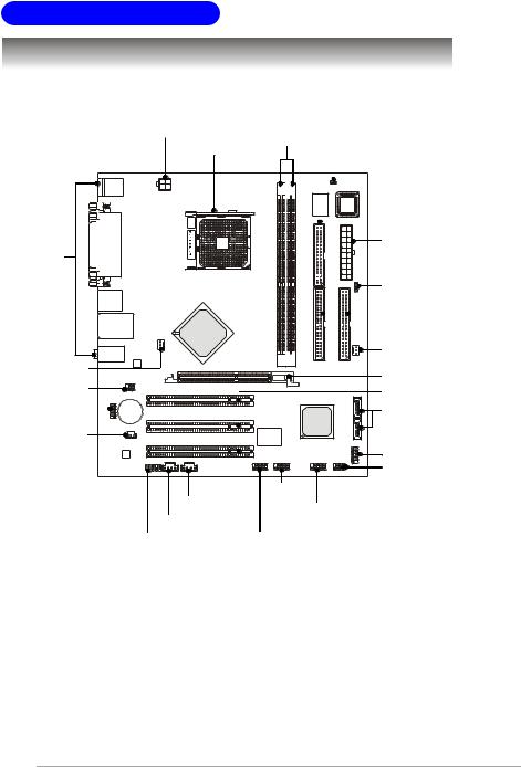
Quick Components Guide
JPW1, p.2-8 |
|
|
JCI1, p.2-18 |
|
|
|
|
CPU, p.2-3 |
DIMM1-2, p.2-6 |
||
|
|
||
|
|
|
FDD1, p.2-14 |
|
|
|
JWR1, p.2-8 |
I/O Ports, |
|
|
|
p.2-9 |
|
|
|
|
|
|
JBAT1, p.2-21 |
|
|
|
IDE1, IDE2, |
|
|
|
p.2-15 |
|
|
|
SFAN1, |
CPUFAN1, |
|
|
p.2-14 |
|
|
|
|
p.2-14 |
|
|
AGP slot, p.2-22 |
JIR1, p.2-19 |
|
|
PCI slots, p.2-22 |
|
|
|
|
JCOM1, p.2-18 |
|
|
SATA1/2, p.2-16 |
JSP1, p.2-20 |
|
|
|
|
|
|
JFP1, p.2-17 |
|
|
|
JFP2, p.2-17 |
JAUX1, p.2-18 |
JUSB1/2, p.2-15 |
||
|
|
|
|
JCD1, p.2-18 |
|
|
|
JAUD1, p.2-19 |
J1394_1, p.2-20 |
||
2- 2
Hardware Setup
Central Processing Unit: CPU
The mainboard supports AMD® Athlon64/ Sempron processor. The mainboard uses a CPU socket called Socket-754 for easy CPU installation. When you are installing the CPU, make sure the CPU has a heat sink and a cooling fan attached on the top to prevent overheating. If you do not have the heat sink and cooling fan, contact your dealer to purchase and install them before turning on the computer.
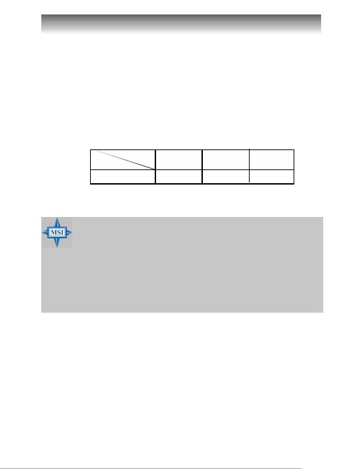
Memory Speed/CPU FSB Support Matrix
|
DDR266 |
DDR333 |
DDR400 |
FSB800 |
OK |
OK |
OK |
MSI Reminds You...
Overheating
Overheating will seriously damage the CPU and system, always make sure the cooling fan can work properly to protect the CPU from overheating.
Replacing the CPU
While replacing the CPU, always turn off the ATX power supply or unplug the power supply’s power cord from grounded outlet first to ensure the safety of CPU.
2- 3
MS-7181 Micro-ATX M ainboard
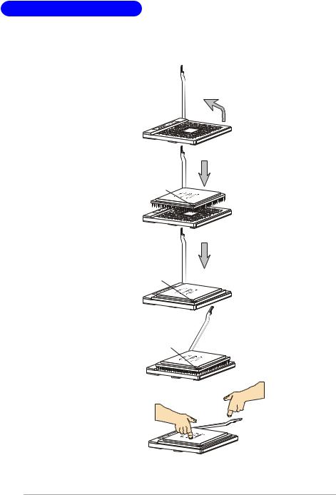
CPU Installation Procedures for Socket 754
1.Please turn off the power and unplug the power cord before installing the CPU.
|
O pen Lever |
|
Sliding |
90 degree |
|
Plate |
||
|
2. Pull the lever sideways away from the socket. Make sure to raise the lever up to a 90-de- gree angle.
G old arrow
3. Look for the gold arrow. The gold arrow should point as picture shown. The CPU can only fit in the correct orientation.
4.If the CPU is correctly installed, the pins should be completely embedded into the socket and can not be seen. Please note that any violation of the correct installation proc edures may cause permanent damages to your mainboard.
5.Press the CPU down firmly into the socket and close the lever. As the CPU is likely to move while the lever is being closed, always close the lever with your fingers pressing tightly on top of the CPU to make sure the CPU is properly and completely embedded into the socket.
C orrectC PU placem ent
G old arrow |
O |
|
IncorrectC PU placem ent
G old arrow
X
Press dow n
the C PU 
 C lose
  Lever
Lever
2- 4
Hardware Setup
Installing AMD Athlon64 CPU Cooler Set
W hen you are installing the CPU, make sure the CPU has a heat sink and a cooling fan attached on the top to prevent overheating. If you do not have the heat sink and cooling fan, contact your dealer to purchase and install them before turning on the computer.
1.Position the cooling set onto the retention mechanism. Hook one end of the clip to hook first.
4. Fasten down the lever.
2.Press down the other end of the clip to fasten the cooling set on
t h e t o p o f t h e r e t en t i o n mechanism.
3.Locate the Fix Lever, Safety Hook and the Fixed Bolt. Lift up the intensive fixed lever.
S a f e t y
FixedLever |
Fixed Bolt |
5.Make sure the safety hook completely clasps the fixed bolt of the retention mechanism.
6.Connect the fan power cable from the mounted fan to the CPUFAN1 connector on the board
MSI Reminds You...
While disconnecting the Safety Hook from the fixed bolt, it is necessary to keep an eye on your fingers, because once the Safety Hook is disconnected from the fixed bolt, the fixed lever will spring back instantly.
2- 5
MS-7181 Micro-ATX M ainboard
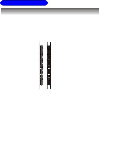
Memory
The mainboard provides two slots for 184-pin DDR SDRAM DIMM (Double In-Line Memory Module) modules and supports up to 2GB memory size. You can install PC3200/DDR400, PC2700/DDR333 & PC2100/DDR266 modules on the DDR DIMM slots (DDR 1~2).
For the updated supporting memory modules, please visit http://www.msi.com.tw/ program/products/mainboard/mbd/pro_mbd_trp_list.php.
DDR DIMM Slots
(DIMM1~2)
Introduction to DDR SDRAM
DDR (Double Data Rate) SDRAM is similar to conventional SDRAM, but doubles the rate by transferring data twice per cycle. It uses 2.5 volts as opposed to 3.3 volts used in SDR SDRAM, and requires 184-pin DIMM modules rather than 168-pin DIMM modules used by SDR SDRAM. High memory bandwidth makes DDR an ideal solution for high performance PC, workstations and servers.
2- 6
Hardware Setup
DDR DIMM Module Combination
Install at least one DIMM module on the slots. Memory modules can be installed on the slots in any order. You can install either singleor double-sided modules to meet your own needs.
Memory modules can be installed in any combination as follows:
Slot |
Memory Module |
Total Memory |
|
|
|
DIMM 1 |
S/D |
64MB~1GB |
(Bank 0 & 1) |
|
|
DIMM 2 |
S/D |
64MB~1GB |
(Bank 2 & 3) |
|
|
Maximum System Memory Supported |
64MB~2GB |
|
|
|
|
S: Single Side |
D: Double Side |
|
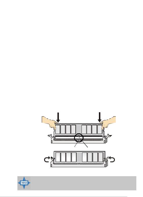
Installing DDR Modules
1.The DDR DIMM has only one notch on the center of module. The module will only fit in the right orientation.
2.Insert the DIMM memory module vertically into the DIMM slot. Then push it in until the golden finger on the memory module is deeply inserted in the socket.
3.The plastic clip at each side of the DIMM slot will automatically close.
Volt Notch
MSI Reminds You...
You can barely see the golden finger if the module is properly inserted in the socket.
2- 7
MS-7181 Micro-ATX M ainboard
Power Supply
The mainboard supports ATX power supply for the power system. Before inserting the power supply connector, always make sure that all components are installed properly to ensure that no damage will be caused.
ATX 20-Pin Power Connector: JWR1
This connector allows you to connect to an ATX power supply. To connect to the ATX power supply, make sure the plug of the power supply is inserted in the proper orientation and the pins are aligned. Then push down the power supply firmly into the connector.
10 |
20 |
PIN |
SIGNAL |
PIN |
SIGNAL |
|
|
|
1 |
3.3V |
11 |
3.3V |
|
|
|
2 |
3.3V |
12 |
-12V |
|
|
|
3 |
GND |
13 |
GND |
|
|
|
4 |
5V |
14 |
PS_ON |
|
|
|
5 |
GND |
15 |
GND |
|
|
|
6 |
5V |
16 |
GND |
|
|
|
7 |
GND |
17 |
GND |
|
1 |
11 |
8 |
PW_OK |
18 |
-5V |
|
9 |
5V_SB |
19 |
5V |
|||
JWR1 |
|
|||||
|
10 |
12V |
20 |
5V |
ATX 12V Power Connector: JPW1
This 12V power connector is used to provide power to the CPU.
4 2 |
PIN |
SIGNAL |
|
|
JPW1 |
1 |
GND |
JPW1 Pin Definition |
|
|
2 |
GND |
|
|
|
|
|
|
||
3 |
1 |
|
3 |
12V |
|
|
|
|
4 |
12V |
|
MSI Reminds You...
There is a mechanism of this mainboard to protect it from being damaged. The power will shut down automatically in two conditions: the temperature of CPU reaches 100oC, or the low voltage occurs during booting up. Please follow the instructions below for this issue:
1.The power LED will blink continously. You should unplug the power cord or turn off the power switch.
2.After the power LED stop blinking, plug on the power cord or turn on the power switch, then you can reboot your system again.
2- 8
Hardware Setup
Back Panel
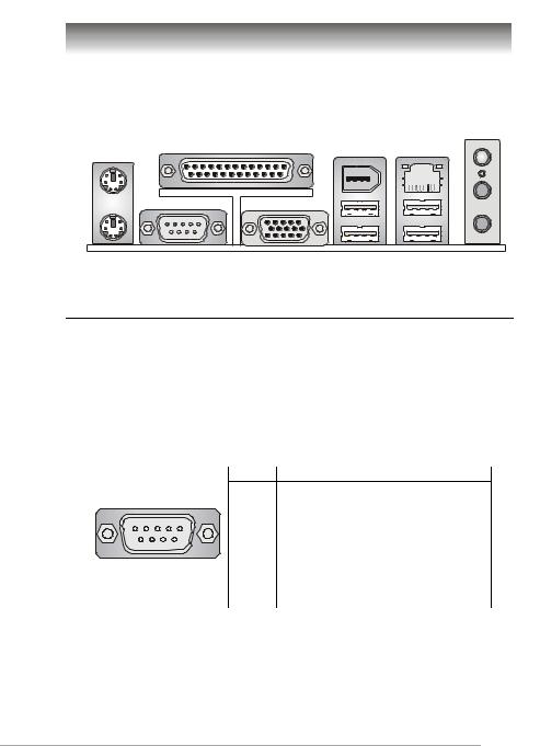
View of the Back Panel
The back panel provides the following connectors:
|
(optional) |
L-in |
Parallel |
1394 |
|
Mouse |
Port |
LAN |
Keyboard COM 1 |
VGA Port USB Ports USB Ports L-out |
|
MIC |
Serial Port: COM1
The mainboard provides one 9-pin mail DIN connector as serial port COM1. The serial port is a 16550A high speed communication port that sends/receives 16 bytes FIFOs. You can attach a serial mouse or other serial device directly to it.
|
|
|
|
|
|
|
|
Pin Definition |
|
|
|
|
|
|
PIN |
SIGNAL |
DESCRIPTION |
1 |
2 |
3 |
4 |
|
5 |
1 |
DCD |
Data Carry Detect |
|
2 |
SIN |
Serial In or Receive Data |
|||||
|
|
|
|
|
|
|||
|
|
|
|
|
|
3 |
SOUT |
Serial Out or Transmit Data |
|
|
|
|
|
|
4 |
DTR |
Data Terminal Ready |
|
|
|
|
|
|
5 |
GND |
Ground |
6 |
7 |
|
8 |
9 |
|
6 |
DSR |
Data SetReady |
|
|
7 |
RTS |
Request To Send |
||||
|
|
|
|
|
|
|||
|
COM1 |
|
|
8 |
CTS |
Clear To Send |
||
|
|
|
|
|
|
9 |
RI |
Ring Indicate |
2- 9
MS-7181 Micro-ATX M ainboard
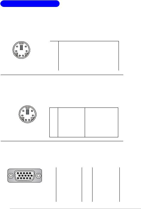
Mouse Connector
The mainboard provides a standard PS/2® mouse mini DIN connector for attaching a PS/2® mouse. You can plug a PS/2® mouse directly into this connector. The connector location and pin assignments are as follows.
|
|
|
|
Pin Definition |
||
6 |
5 |
|
PIN |
SIGNAL |
DESCRIPTION |
|
4 |
|
3 |
1 |
Mouse Data |
Mouse data |
|
|
2 |
NC |
Noconnection |
|||
|
|
|
||||
|
|
|
3 |
GND |
Ground |
|
2 |
1 |
|
4 |
VCC |
+5V |
|
PS/2 Mouse |
|
5 |
MouseClock |
Mouseclock |
||
|
6 |
NC |
Noconnection |
|||
(6-pin Female) |
||||||
|
|
|
||||
Keyboard Connector
The mainboard provides a standard PS/2® keyboard mini DIN connector for attaching a PS/2® keyboard. You can plug a PS/2® keyboard directly into this connector. The connector location and pin assignments are as follows.
|
|
|
Pin Definition |
||
6 |
5 |
PIN |
SIGNAL |
DESCRIPTION |
|
|
|
||||
4 |
3 |
1 |
Keyboard Data |
Keyboard data |
|
|
|
2 |
NC |
Noconnection |
|
2 |
1 |
3 |
GND |
Ground |
|
4 |
VCC |
+5V |
|||
PS/2 Keyboard |
|||||
5 |
KeyboardClock |
Keyboardclock |
|||
(6-pin Female) |
6 |
NC |
Noconnection |
||
VGA Connector
The mainboard provides a DB 15-pin female connector to connect a VGA monitor.
|
|
|
Pin Definition |
|
||
5 |
1 |
Pin |
Signal Description |
Pin |
Signal Description |
|
|
|
|||||
|
|
1 |
RED |
9 |
+5V |
|
|
|
2 |
GREEN |
10 |
GND |
|
|
|
3 |
BLUE |
11 |
N/C |
|
15 |
11 |
4 |
N/C |
12 |
SDA |
|
VGA Connector |
5 |
GND |
13 |
Horizontal Sync |
||
6 |
GND |
14 |
Vertical Sync |
|||
(DB 15-pin) |
||||||
7 |
GND |
15 |
SCL |
|||
|
|
8 |
GND |
|
|
|
2-10
Hardware Setup
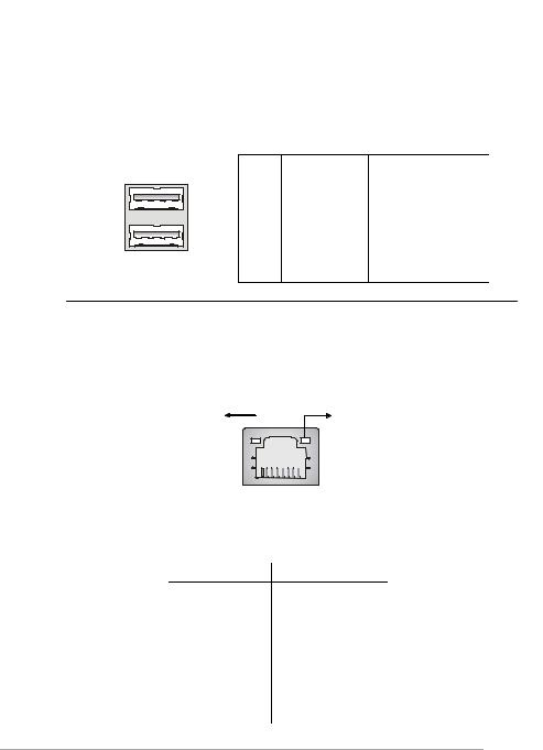
USB Ports
The mainboard provides a UHCI (Universal Host Controller Interface) Universal Serial Bus root for attaching USB devices such as keyboard, mouse or other USB-compat- ible devices. You can plug USB devices directly into the ports.
1 |
2 |
3 |
4 |
5 |
6 |
7 |
8 |
USB Ports
Pin Definition
PIN |
SIGNAL |
DESCRIPTION |
1 |
VCC |
+5V |
2 |
-Data 0 |
Negative Data Channel 0 |
3 |
+Data 0 |
Positive Data Channel 0 |
4 |
GND |
Ground |
5 |
VCC |
+5V |
6 |
-Data 1 |
Negative Data Channel 1 |
7 |
+Data 1 |
Positive Data Channel 1 |
8 |
GND |
Ground |
RJ-45 LAN Jack
The mainboard provides one standard RJ-45 jack for connection to Local Area Network (LAN). You can connect a network cable to the LAN jack.
ActivityIndicator |
LinkIndicator |
|
8 |
1 |
|
RJ-45 LAN Jack |
|
|
10/100 LAN Pin Definition |
|
PIN |
SIGNAL |
DESCRIPTION |
1 |
TDP |
Transmit Differential Pair |
2 |
TDN |
Transmit Differential Pair |
3 |
RDP |
Receive Differential Pair |
4 |
NC |
Not Used |
5 |
NC |
Not Used |
6 |
RDN |
Receive Differential Pair |
7 |
NC |
Not Used |
8 |
NC |
Not Used |
2-11
MS-7181 Micro-ATX M ainboard
IEEE 1394 Port (Optional)
The back panel provides one standard IEEE 1394 port. The IEEE1394 high-speed serial bus complements USB by providing enhanced PC connectivity for a wide range of devices, including consumer electronics audio/video (A/V) appliances, storage peripherals, other PCs, and portable devices.
IEEE1394 Port
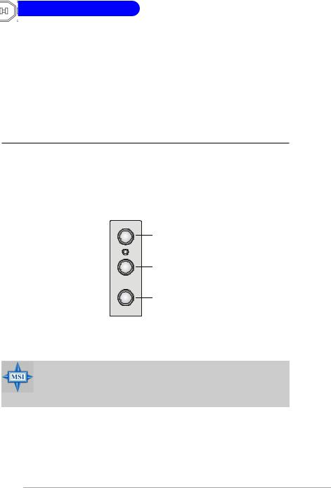
Audio Port Connectors
Line Out is a connector for Speakers or Headphones. Line In is used for external CD player, Tape player, or other audio devices. Mic is a connector for microphones.
Line In
Line Out
MIC
MSI Reminds You...
For advanced audio application, VIA VT1617 audio chip is provided to offer support for 6-channel audio operation and can turn rear audio connectors from 2-channel to 4-/6-channel audio.
2-12
Hardware Setup
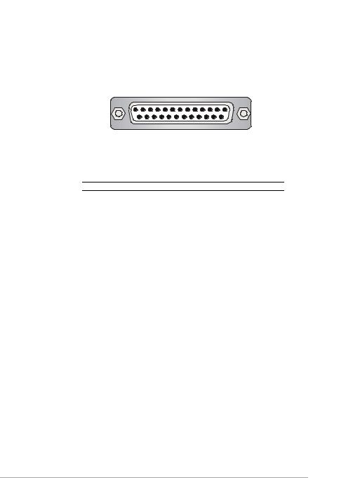
Parallel Port
The mainboard provides a 25-pin female centronic connector as LPT. A parallel port is a standard printer port that supports Enhanced Parallel Port (EPP) and Extended Capabilities Parallel Port (ECP) mode.
|
13 |
1 |
|
25 |
14 |
|
Pin Definition |
|
PIN |
SIGNAL |
DESCRIPTION |
1 |
STROBE |
Strobe |
2 |
DATA0 |
Data0 |
3 |
DATA1 |
Data1 |
4 |
DATA2 |
Data2 |
5 |
DATA3 |
Data3 |
6 |
DATA4 |
Data4 |
7 |
DATA5 |
Data5 |
8 |
DATA6 |
Data6 |
9 |
DATA7 |
Data7 |
10 |
ACK# |
Acknowledge |
11 |
BUSY |
Busy |
12 |
PE |
PaperEnd |
13 |
SELECT |
Select |
14 |
AUTO FEED# |
AutomaticFeed |
15 |
ERR# |
Error |
16 |
INIT# |
Initialize Printer |
17 |
SLIN# |
Select In |
18 |
GND |
Ground |
19 |
GND |
Ground |
20 |
GND |
Ground |
21 |
GND |
Ground |
22 |
GND |
Ground |
23 |
GND |
Ground |
24 |
GND |
Ground |
25 |
GND |
Ground |
2-13
MS-7181 Micro-ATX M ainboard
Connectors
The mainboard provides connectors to connect FDD, IDE HDD, front panel of the system case, audio ports, USB Ports, and CPU/System FANs.
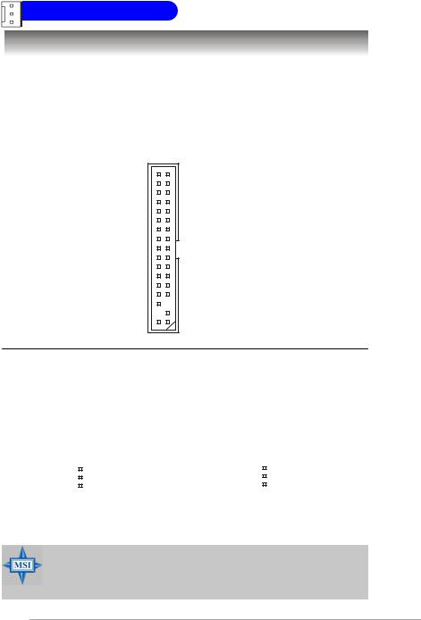
Floppy Disk Drive Connector: FDD1
The mainboard provides a standard floppy disk drive connector that supports 360KB, 720KB, 1.2MB, 1.44MB and 2.88MB floppy disk types.
FDD1
Fan Power Connectors: CPUFAN1, SFAN1
The CPUFAN1 (processor fan) and SFAN1 (system fan) support system cooling fan with +12V. It supports 3-pin head connector. W hen connecting the wire to the connectors, always take note that the red wire is the positive and should be connected to the +12V, the black wire is Ground and should be connected to GND. If the mainboard has a System Hardware Monitor chipset on-board, you must use a specially designed fan with speed sensor to take advantage of the CPU fan control.
|
|
|
|
|
|
|
|
SENSOR |
|
|
|
|
|
|
|
|
+12V |
|
|
|
|
|
|
|
|
GND |
|
|
|
|
|
|
|
|
|
CPUFAN1 |
SFAN1 |
Fan Connector |
||||||
|
|
|
|
|
Pin Definition |
|||
MSI Reminds You...
1.Always consult the vendors for proper CPU cooling fan.
2.CPUFAN1 supports Smart Fan control, you may set up the smart fan control functions in the BIOS setup.
2-14
 Loading...