


MSI
MICRO-STAR INTERNATIONAL
MS-6382 (v2.X) Micro ATX Mainboard
Version 2.0
G52-MA00563
i

Manual Rev: 2.0
Release Date: March 2002
FCC-B Radio Frequency Interference Statement
This equipment has been tested and found to comply with the limits for a class B digital device, pursuant to part 15 of the FCC rules. These limits are designed to provide reasonable protection against harmful interference when the equipment is operated in a commercial environment. This equipment generates, uses and can radiate radio frequency energy and, if not installed and used in accordance with the instruction manual, may cause harmful interference to radio communications. Operation of this equipment in a residential area is likely to cause harmful interference, in which case the user will be required to correct the interference at his own expense.
Notice 1
The changes or modifications not expressly approved by the party responsible for compliance could void the user’s authority to operate the equipment.
Notice 2
Shielded interface cables and A.C. power cord, if any, must be used in order to comply with the emission limits.
VOIR LA NOTICE D’INSTALLATION AVANT DE RACCORDER AU RESEAU.
Micro-Star International MS-6382
Tested to comply
withFCCStandard
For Home or Office Use
ii
Edition
March 2002
Copyright Notice
The material in this document is the intellectual property of MICRO-STAR INTERNATIONAL. We take every care in the preparation of this document, but no guarantee is given as to the correctness of its contents. Our products are under continual improvement and we reserve the right to make changes without notice.
Trademarks
All trademarks are the properties of their respective owners.
Intel® and Pentium® are registered trademarks of Intel Corporation.
PS/2 and OS®/2 are registered trademarks of International Business Machines Corporation.
Windows® 95/98/2000/NT/XP are registered trademarks of Microsoft Corporation.
Netware® is a registered trademark of Novell, Inc.
Award® is a registered trademark of Phoenix Technologies Ltd. AMI® is a registered trademark of American Megatrends Inc.
Revision History
Revision |
Revision History |
Date |
2.0 |
First Release for PCB 2.X |
March 2002 |
iii

Safety Instructions
1.Read the safety instructions carefully.
2.Save this User’s Guide for possible use later.
3.Keep this equipment away from humidity.
4.Lay this equipment on a stable and flat surface before setting it up.
5.The openings on the enclosure are used for air convection and to prevent the equipment from overheating. Note: Do not cover the openings.
6.Make sure that the power voltage is within its safety range and has been adjusted properly to the value of 110/220V before connecting the equipment to the power inlet.
7.Place the power cord in a way that people are unlikely to step on it. Do not place anything on the power cord.
8.Always unplug the power cord before inserting any add-on card or module.
9.All cautions and warnings on the equipment should be noted.
10.Never pour any liquid into the opening that could damage the equipment or cause an electrical shock.
11.If any of the following situations arises, get the equipment checked by a service personnel:
l the power cord or plug is damaged
l liquid has penetrated into the equipment
l the equipment has been exposed to moisture
lthe equipment has not work well or you can not get it work according to User’s Guide
lthe equipment was dropped and damaged
lthe equipment has obvious signs of breakage
12.Do not leave the equipment in an unconditioned environment with a storage temperature of 600 C (1400F) or above, which may damage the equipment.
CAUTION: To prevent explosion caused by improper battery replacement, use the same or equivalent type of battery recommended by the manufacturer only.
iv
CONTENTS
Chapter 1. Getting Started ........................................................................ |
1-1 |
Mainboard Specification ...................................................................... |
1-2 |
Mainboard Layout ............................................................................... |
1-4 |
Quick Components Guide .................................................................... |
1-5 |
Chapter 2. Hardware Setup ....................................................................... |
2-1 |
Central Processing Unit: CPU .............................................................. |
2-2 |
CPU Installation Procedures ......................................................... |
2-2 |
Thermal Issue for CPU .................................................................. |
2-3 |
CPU Core Speed Derivation Procedure ......................................... |
2-3 |
Memory ................................................................................................ |
2-4 |
Introduction to DDR SDRAM ....................................................... |
2-4 |
DDR Module Combination ............................................................ |
2-5 |
Installing DDR Modules ............................................................... |
2-5 |
Power Supply ....................................................................................... |
2-6 |
ATX 20-Pin Power Connector: JWR1 ............................................ |
2-6 |
Back Panel ............................................................................................ |
2-7 |
Mouse Connector ......................................................................... |
2-7 |
Keyboard Connector ..................................................................... |
2-8 |
USB Connectors ............................................................................ |
2-8 |
Serial Port Connectors: COM A & COM B .................................... |
2-9 |
Joystick/Midi Connectors ............................................................. |
2-9 |
Audio Port Connectors ................................................................. |
2-9 |
Parallel Port Connector: LPT1 ...................................................... |
2-10 |
RJ-45 LAN Jack (optional) ........................................................... |
2-11 |
v
Connectors ......................................................................................... |
2-12 |
Floppy Disk Drive Connector: FDD1 ........................................... |
2-12 |
Chassis Intrusion Switch Connector: J1 ...................................... |
2-12 |
Hard Disk Connectors: IDE1 & IDE2 ........................................... |
2-13 |
CD-In Connector: CD_IN ............................................................ |
2-14 |
Aux Line-In Connector: AUX_IN ................................................ |
2-14 |
Modem-In Connector: MODEM_IN ........................................... |
2-14 |
Fan Power Connectors: CFAN1/SFAN1 ...................................... |
2-15 |
Power Saving LED Connector: JGL1 ........................................... |
2-16 |
Power Saving Switch Connector: JGS1 ........................................ |
2-17 |
IrDA Infrared Module Header: FPIR ........................................... |
2-17 |
Front Panel Audio Connector: JAUD1 ........................................ |
2-18 |
Front Panel Connectors: JFP1 & JFP2 ......................................... |
2-19 |
Front USB Connector: USB1 ....................................................... |
2-20 |
Jumpers .............................................................................................. |
2-21 |
Clear CMOS Jumper: JBAT1 ........................................................ |
2-21 |
CPU Clock Frequency Selection: SW1 ........................................ |
2-22 |
Slots ................................................................................................... |
2-23 |
AGP Slot ...................................................................................... |
2-23 |
PCI Slots ...................................................................................... |
2-23 |
CNR (Communication Network Riser) ......................................... |
2-23 |
PCI Interrupt Request Routing .................................................... |
2-24 |
Chapter 3. AWARD® BIOS Setup ............................................................ |
3-1 |
Entering Setup ...................................................................................... |
3-2 |
Control Keys ................................................................................. |
3-2 |
Getting Help .................................................................................. |
3-3 |
The Main Menu ................................................................................... |
3-4 |
Standard CMOS Features .................................................................... |
3-6 |
vi
Advanced BIOS Features .................................................................... |
3-8 |
Advanced Chipset Features ............................................................... |
3-12 |
Integrated Peripherals ........................................................................ |
3-16 |
Power Management Setup ................................................................. |
3-21 |
PNP/PCI Configurations ..................................................................... |
3-26 |
PC Health Status ................................................................................ |
3-29 |
Frequency/Voltage Control ................................................................ |
3-30 |
Load Fail-Safe/Optimized Defaults ..................................................... |
3-31 |
Set Supervisor/User Password ........................................................... |
3-32 |
Glossary .................................................................................................... |
G-1 |
vii

|
Getting Started |
|
|
|
1 |
Getting Started |
|
|
The MS6382 v2.X Micro-ATX mainboard is a high performance computer mainboard based on VIA KT266A & VT8233A chipsets. The KT266A chipset is ideal for high quality and high integration desktop and notebook AGP/PCI/LPC computer systems based on Socket A processors.
The VT8233A V-Link Client controller is a highly integrated PCI/LPC controller. It supports three PCI slots of arbitration and decoding for all integrated functions and LPC bus.
For sophisticated power management, the KT266A chipset provides independent clock stop control for the SDRAM, PCI buses and Dynamic CKE control for powering down of the SDRAM. A seperate suspend-well plane is implemented for the SDRAM control signals for the Suspend-to- DRAM operation.
TOPICS |
|
Mainboard Specification |
1-2 |
Mainboard Layout |
1-4 |
Quick Components Guide |
1-5 |
1-1

Chapter 1
Mainboard Specification
CPU
 Socket 462 (Socket A) for AMD® DuronTM/AthlonTM processor with 200/ 266MHzFSB
 Support 600MHz up to 1.5GHz processor
Chipset
 VIA® KT266A Chipset
-Support 66MHz V-Link Host interface with peak bandwidth of 266MB/s
-Advanced ECC memory controller supporting PC133/PC100 SDR SDRAM and PC2100/1600 DDR SDRAM
-Full featured AGP Controller: AGP v2.0 compliant
 VIA® VT8233A Chipset
-High bandwidth V-Link client controller
-Integrated faster Ethernet controller
-Direct sound ready AC97 digital audio controller
-Ultra DMA 33/66/100/133 master mode EIDE controller
-Support both ACPI and legacy APM power management
Clock Generator
 Cypress CY28341OC rev. D (support 2 DDR DIMM)
MainMemory
 Support four memory banks using two 184-pin (100/133MHz) DDR DIMM
  Support a maximum memory size of 2GB
Slots
 One (Accelerated Graphics Port) AGP slot One CNR (Communication Network Riser) slot
 Three 32-bit Master PCI Bus slots
- 3rd PCI with “MEDION” specification reserved  Supports 3.3v/5v PCI bus Interface
On-BoardIDE
 Dual Channel master mode IDE controller on the VIA® VT8233A Chipset provides IDE HDD/CD-ROM with PIO, Bus Master and Ultra DMA 33/66/ 100/133 operation modes
 Can connect up to four IDE devices
1-2
Getting Started
Audio
 2 channels S/W Audio CODEC, Realtek ALC201A
 AC97’s digital link controller was integrated in VIA VT8233A
On-Board Peripherals
 On-Board Peripherals include:
-1 floppy port supports 2 FDD with 360K, 720K, 1.2M, 1.44M and 2. 88Mbytes.
-2 serial ports (COMA + COM B)
-1 parallel port supports SPP/EPP/ECP mode
-4 USB ports (2 x Rear / 2x Front)
-1 Audio/Game port
-1 optional RJ-45 LAN jack (Reaktek RTL8100BL)
BIOS
 The mainboard BIOS provides “Plug & Play” BIOS which detects the peripheral devices and expansion cards of the board automatically.
  The mainboard provides a Desktop Management Interface (DMI) function which records your mainboard specifications.
Dimension
 M-ATX Form Factor: 9.6 in. x 8.25 in.
Mounting
 6 mounting holes
Others
 Support STR/STD (S3/S4)
 Support PS2/USB KBD/Mouse Wakeup function in S3 mode
 PC 2001 Compliance
 Support Chassis Intrusion Detection & SIR
1-3

Chapter 1
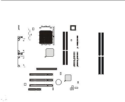
Mainboard Layout
Top : mouse |
|
CFAN1 |
|
|
BIOS |
|
|
Bottom: keyboard |
|
|
|
|
|||
|
SOCKET 462 |
|
|
|
|
||
|
|
|
|
|
|
|
|
Top: LAN Jack |
ATX |
SupplyPower |
|
|
|
|
|
Bottom: USB |
|
|
|
|
|
||
ports |
|
|
|
|
|
Winbond |
|
|
|
|
|
|
|
W83697HF |
|
|
|
|
|
|
|
J1 |
1 |
|
|
|
|
|
|
FDD |
|
Top : Parallel Port |
|
|
|
|
|
||
|
|
|
|
|
|
||
Bottom: |
|
|
|
|
|
|
|
COM A |
|
|
|
|
|
|
|
COM B |
|
|
|
|
|
|
|
|
|
|
VIA |
|
|
|
|
|
|
|
KT266A |
|
|
|
|
Top : |
|
|
|
|
|
|
|
Game port |
|
|
|
|
|
|
|
Bottom: |
CD_IN |
|
|
|
|
|
|
|
|
|
|
|
|
|
|
Line-Out |
|
|
|
|
|
|
|
Line-In |
|
|
|
|
|
|
|
Mic |
|
|
|
|
|
|
|
|
|
AUX_IN |
AGP Slot |
|
|
|
|
|
|
|
|
|
|
|
|
MODEM_IN |
|
|
|
|
1 |
2 |
|
|
|
DDR 1 |
DDR 2 |
IDE |
IDE |
||
|
|
|
PCI Slot 1 |
||||
RTL |
|
|
|
|
|
|
|
|
|
|
|
|
|
|
|
8100BL |
|
|
SW1 |
|
|
|
|
|
|
|
|
|
|
|
|
|
|
|
PCI Slot 2 |
|
VT8233A |
|
|
|
|
|
|
|
|
|
|
|
|
|
|
BATT |
|
|
JGS1 |
Codec |
|
|
+ |
|
|
||
|
PCI Slot 3 |
|
|
|
|||
ALC201A |
|
|
|
|
SFAN1 |
|
|
|
|
|
|
|
|
|
|
|
|
|
|
USB1 |
|
|
JFP2 |
|
|
|
JAUD1 |
|
|
|
|
|
|
|
|
|
|
|
|
CNR |
|
JBAT1 |
|
|
FPIR |
|
|
|
|
|
|
|
|
JGL1 JFP1 |
|
MS-6382 v2.X Micro ATX Mainboard
1-4

Getting Started
Quick Components Guide
Component |
Function |
Reference |
|
|
|
JWR1 |
ATX 20-pin Power Connector |
See p. 2-6 |
|
|
|
USB Connectors |
Connecting to USB devices |
See p. 2-8 |
|
|
|
COM A & B Connector |
Connecting to Serial ports |
See p. 2-9 |
|
|
|
Game/Audio Connectors |
Connecting to Game/Audio devices |
See p. 2-9 |
|
|
|
LPT1 |
Parallel port connector |
See p. 2-10 |
|
|
|
RJ-45 LAN Jack |
Connecting to LAN devices |
See p. 2-11 |
|
|
|
FDD1 |
Floppy disk drive connector |
See p. 2-12 |
|
|
|
J1 |
Chassis intrusion switch |
See p. 2-12 |
|
|
|
IDE1~ IDE2 |
Hard disk connectors |
See p. 2-13 |
|
|
|
CD_IN |
CD-in connector |
See p. 2-14 |
|
|
|
AUX_IN |
Aux line-in connector |
See p. 2-14 |
|
|
|
MODEM_IN |
Modem-in connector |
See p. 2-14 |
|
|
|
CFAN1/SFAN1 |
Fan power connectors |
See p. 2-15 |
|
|
|
JGL1 |
Power Saving LED Connector |
See p. 2-16 |
|
|
|
JGS1 |
Power Saving Switch Connector |
See p. 2-17 |
|
|
|
FPIR |
IrDA infrared module connector |
See p. 2-17 |
|
|
|
JAUD1 |
Front panel audio connector |
See p. 2-18 |
|
|
|
JFP1 & JFP2 |
Front panel connectors |
See p. 2-19 |
|
|
|
USB1 |
Front USB connector |
See p. 2-20 |
|
|
|
JBAT1 |
Clear CMOS jumper |
See p. 2-21 |
|
|
|
SW1 |
CPU FSB jumper |
See p. 2-22 |
|
|
|
AGP Slot |
Connecting to expansion cards |
See p. 2-23 |
|
|
|
PCI Slots |
Connecting to expansion cards |
See p. 2-23 |
|
|
|
CNR Slots |
Connecting to expansion cards |
See p. 2-23 |
|
|
|
1-5

|
Hardware Setup |
|
|
|
2 |
Hardware Setup |
|
|
This chapter provides you with the information about hardware setup procedures. While doing the installation, be careful in holding the components and follow the installation procedures. For some components, if you install in the wrong orientation, the components will not work properly.
Use a grounded wrist strap before handling computer components. Static electricity may damage the components.
TOPICS |
|
Central Processing Unit: CPU |
2-2 |
Memory |
2-5 |
Power Supply |
2-6 |
Back Panel |
2-7 |
Connectors |
2-12 |
Jumpers |
2-21 |
Slots |
2-23 |
2-1
Chapter 2
Central Processing Unit: CPU
The mainboard supports AMD® DuronTM/AthlonTM processor. The mainboard uses a CPU socket called Socket-462 for easy CPU installation. When you are installing the CPU, make sure the CPU has a heat sink and a cooling fan attached on the top to prevent overheating. If you do not find the heat sink and cooling fan, contact your dealer to purchase and install them before turning on the computer.
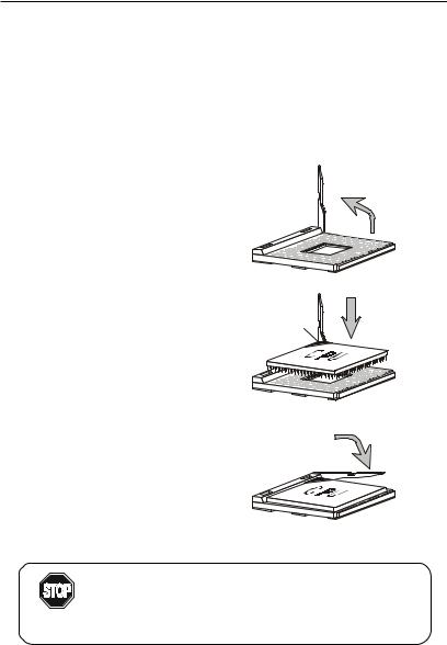
CPU Installation Procedures
1.Pull the lever sideways away from the socket. Then, raise the lever up to a 90-degree angle.
2.Look for the cut edge. The cut edge should point towards the lever pivot. The CPU will only fit in the correct orientation.
3.Hold the CPU down firmly, and then close the lever to complete the installation.
Open Lever
Sliding
Plate
Cut edge
Close
Lever
Overheating will seriously damage the CPU and system, always make sure the cooling fan can work properly to
WARNING! protect the CPU from overheating.
2-2

Hardware Setup
Thermal Issue for CPU
As processor technology pushes to faster speeds and higher performance, thermal management becomes increasingly crucial when building computer systems. Maintaining the proper thermal environment is key to reliable operation. As such, the processor must be maintained in the specified thermal requirements. AMD recommends the use of high performance thermal interface material.
AMD Athlon™ processor with a speed of 600MHz and above requires LARGER heatsink and fan. You also need to add thermal grease between the CPU and heatsink to improve heat dissipation. Then, make sure that the CPU and heatsink are securely fastened and in good contact with each other. These are needed to prevent damaging the processor and ensuring reliable operation.
You can check AMD’s web site for more information on proper cooling.
CPU Core Speed Derivation Procedure
If |
CPUClock |
= |
100MHz |
|
Core/Bus ratio |
= |
7 |
then |
CPU core speed |
= |
Host Clock x Core/Bus ratio |
|
|
= |
100MHzx7 |
|
|
= |
700MHz |
While replacing the CPU, always turn off the ATX
power supply or unplug the power cable of the ATX WARNING! power supply from grounded outlet first to ensure the
safety of CPU.
2-3
Chapter 2
Memory
The mainboard provides 2 slots for 184-pin, 2.5V unbuffered DDR DIMM with 4 memory banks. You can install PC1600 or PC2100 DDR SDRAM modules on the DDR DIMM slots (DDR 1~2). To operate properly, at least one DIMM module must be installed.
|
|
|
|
|
|
|
|
|
|
|
|
|
|
|
|
|
|
|
|
|
|
|
|
|
|
|
|
|
|
|
|
|
|
|
|
|
|
|
|
|
|
|
|
|
|
|
|
|
|
|
|
|
|
|
|
|
|
|
|
|
|
|
|
|
|
|
|
|
|
|
|
|
|
|
|
|
|
|
|
|
|
|
|
|
|
|
|
|
|
|
|
|
|
|
|
|
|
|
|
|
|
|
|
|
|
|
|
|
|
|
|
|
|
|
|
|
|
|
|
|
|
|
|
|
|
|
|
|
|
|
|
|
|
|
|
|
|
|
|
|
|
|
|
|
|
|
|
|
|
|
|
|
|
|
|
|
|
|
|
|
|
|
|
|
|
|
|
|
|
|
|
|
|
|
|
|
|
|
|
|
|
|
|
|
|
|
|
|
|
|
|
|
|
|
|
|
|
|
|
|
|
|
|
|
|
|
|
|
|
|
|
|
|
|
|
|
|
|
|
|
|
|
|
|
|
|
|
|
|
|
|
|
|
|
|
|
|
|
|
|
|
|
|
|
|
|
|
|
|
|
|
|
|
|
|
|
|
|
|
|
|
|
|
|
|
|
|
|
|
|
|
|
|
|
|
|
|
|
|
|
|
|
|
|
|
|
|
|
|
|
|
|
|
|
|
|
|
|
|
|
|
|
|
|
|
|
|
|
|
|
|
|
|
|
|
|
|
|
|
|
|
|
|
|
|
|
|
|
|
|
|
|
|
|
|
|
|
|
|
|
|
|
|
|
|
|
|
|
|
|
|
|
|
|
|
|
|
|
|
|
|
|
|
|
|
|
|
|
|
|
|
|
|
|
|
|
|
|
|
|
|
|
|
|
|
|
|
|
|
|
|
|
|
|
|
|
|
|
|
|
|
|
|
|
|
|
|
|
|
|
|
|
|
|
|
|
|
|
|
|
|
|
|
|
|
|
|
|
|
|
|
|
|
|
|
|
|
|
|
|
|
|
|
|
|
|
|
|
|
|
|
|
|
|
|
|
|
|
|
|
|
|
|
|
|
|
|
|
|
|
|
|
|
|
|
|
|
|
|
|
|
|
|
|
|
|
|
|
|
|
|
|
|
|
|
|
|
|
|
|
|
|
|
|
|
|
|
|
|
|
|
|
|
|
|
|
|
|
|
|
|
|
|
|
|
|
|
|
|
|
|
|
|
|
|
|
|
|
|
|
|
|
|
|
|
|
|
|
|
|
|
|
|
|
|
|
|
|
|
|
|
|
|
|
|
|
|
|
|
|
|
|
|
|
|
|
|
|
|
|
|
|
|
|
|
|
|
|
|
|
|
|
|
|
|
|
|
|
|
|
|
|
|
|
|
|
|
|
|
|
|
|
|
|
|
|
|
|
|
|
|
|
|
|
|
|
|
|
|
|
|
|
|
|
|
|
|
|
|
|
|
|
|
|
|
|
|
|
|
|
|
|
|
|
|
|
|
|
|
|
|
|
|
|
|
|
|
|
|
|
|
|
|
|
|
|
|
|
|
|
|
|
|
|
|
|
|
|
|
|
|
|
|
|
|
|
|
|
|
|
|
|
|
|
|
|
|
|
DDR1 |
|
DDR 2 |
||
|
|
|
|
|
|
|
|
|
|
|
|
|
|
|
|
|
|
|
|
|
|
|
|
|
|
|
|
|
|
|
|
|
|
|
|
|
|
|
|
|
|
|
|
|
|
|
||||
|
|
|
|
|
|
|
|
|
|
|
|
|
|
|
|
|
|
|
|
|
|
|
|
|
|
|
|
|
|
|
|
|
|
|
|
|
|
|
|
|
|
|
|
|
|
|
||||
|
|
|
|
|
|
|
|
|
|
|
|
|
|
|
|
|
|
|
|
|
|
|
|
|
|
|
|
|
|
|
|
|
|
|
|
|
|
|
|
|
|
|
|
|
|
|
||||
|
|
|
|
|
|
|
|
|
|
|
|
|
|
|
|
|
|
|
|
|
|
|
|
|
|
|
|
|
|
|
|
|
|
|
|
|
|
|
|
|
|
|
|
|
|
|
|
|
|
|
|
|
|
|
|
|
|
|
|
|
|
|
|
|
|
|
|
|
|
|
|
|
|
|
|
|
|
|
|
|
|
|
|
|
|
|
|
|
|
|
|
|
|
|
|
|
|
|
|
|
|
|
|
|
|
|
|
|
|
|
|
|
|
|
|
|
|
|
|
|
|
|
|
|
|
|
|
|
|
|
|
|
|
|
|
|
|
|
|
|
|
|
|
|
|
|
|
|
|
|
|
|

 Note: The DDR DIMM slots DO NOT support PC2700 modules.
Introduction to DDR SDRAM
DDR (Double Data Rate) SDRAM is similar to conventional SDRAM, but doubles the rate by transferring data twice per cycle. It uses 2.5 volts as opposed to 3.3 volts used in SDR SDRAM, and requires 184-pin DIMM modules rather than 168-pin DIMM modules used by SDR SDRAM. Two types of DDR SDRAM are available at the time of writing: PC1600, PC2100.
The following table shows the clock and peak bandwidth of each type of DDR SDRAM module:
|
PC2100 |
PC1600 |
|
(DDR266) |
(DDR200) |
|
|
|
Clock |
133MHz |
100MHz |
|
|
|
Peak |
|
|
Bandwidth |
2133MB/s |
1600MB/s |
|
|
|
2-4
Hardware Setup
DDR Module Combination
You can install either single sided or double sided 184-pin DDR DIMM modules into DDR DIMM slots to meet your needs. Different from the SDR DIMM, the DDR DIMM has only one notch on the center of module. The number of pins on either side of the breaks are different. The module will only fit in the right orientation.
You can install memory modules in any combination as follows:
Slot |
Memory Module |
Total Memory |
|
|
|
Slot 1 |
64MB, 128MB, |
64MB~1GB |
(Bank 0 & Bank 1) |
256MB, 512MB, 1GB |
|
Slot 2 |
64MB, 128MB, |
64MB~1GB |
(Bank 2 & Bank 3) |
256MB, 512MB, 1GB |
|
Maximum System Memory Supported |
64MB~2GB |
|
|
|
|
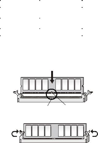
Installing DDR Modules
1.The DDR DIMM has only one notch on the center of module. The module will only fit in the right orientation.
2.Insert the DIMM memory module vertically into the DIMM slot. Then push it in.
Volt notch
3. The plastic clip at each side of the DIMM slot will automatically close.
2-5
Chapter 2
Power Supply
The mainboard supports ATX power supply for the power system. Before inserting the power supply connector, always make sure that all components are installed properly to ensure that no damage will be caused.
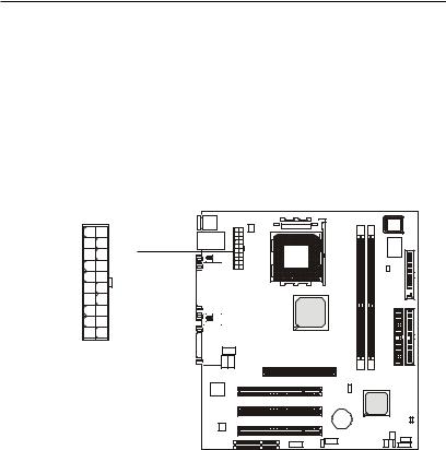
ATX 20-Pin Power Connector: JWR1
This connector allows you to connect to an ATX power supply. To connect to the ATX power supply, make sure the plugs of the power supply is inserted in the proper orientation and the pins are aligned. Then push down the power supply firmly into the connector. The power connector supports instant power on function which means that system will boot up immediately when the power supply connector is inserted on the board.
10 |
20 |
1 |
11 |
JWR1 |
|
JWR1 Pin Definition
PIN |
SIGNAL |
PIN |
SIGNAL |
1 |
3.3V |
11 |
3.3V |
2 |
3.3V |
12 |
-12V |
3 |
GND |
13 |
GND |
4 |
5V |
14 |
PS_ON |
5 |
GND |
15 |
GND |
6 |
5V |
16 |
GND |
7 |
GND |
17 |
GND |
8 |
PW_OK |
18 |
-5V |
9 |
5V_SB |
19 |
5V |
10 |
12V |
20 |
5V |
|
|
|
|
2-6

Hardware Setup
Back Panel
The Back Panel provides the following connectors:
LAN |
Parallel |
Midi/Joystick |
|
Mouse (optional) |
|||
|
Keyboard USB |
COM A |
COM B |
L-out L-in MIC |
Mouse Connector
The mainboard provides a standard PS/2® mouse mini DIN connector for attaching a PS/2® mouse. You can plug a PS/2® mouse directly into this connector. The connector location and pin assignments are as follows:
|
|
|
Pin Definition |
||
6 |
5 |
PIN |
SIGNAL |
DESCRIPTION |
|
1 |
Mouse DATA |
Mouse DATA |
|||
|
|
||||
4 |
3 |
2 |
NC |
No connection |
|
|
|
3 |
GND |
Ground |
|
2 |
1 |
4 |
VCC |
+5V |
|
5 |
Mouse Clock |
Mouse clock |
|||
|
|
||||
PS/2 Mouse (6-pin Female) |
6 |
NC |
No connection |
||
2-7
Chapter 2
Keyboard Connector
The mainboard provides a standard PS/2® keyboard mini DIN connector for attaching a PS/2® keyboard. You can plug a PS/2® keyboard directly into this connector.
6 


 5
5
4 |
3 |
2 1
PS/2 Keyboard (6-pin Female)
Pin Definition
PIN |
SIGNAL |
DESCRIPTION |
|
|
|
1 |
Keyboard DATA |
Keyboard DATA |
2 |
NC |
No connection |
3 |
GND |
Ground |
4 |
VCC |
+5V |
5 |
Keyboard Clock |
Keyboard clock |
6 |
NC |
No connection |
|
|
|
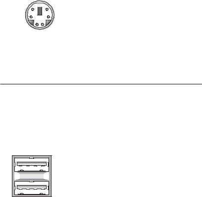
USB Connectors
The mainboard provides a UHCI (Universal Host Controller Interface) Universal Serial Bus root for attaching USB devices such as keyboard, mouse or other USB-compatible devices. You can plug the USB device directly into the connector.
1 |
2 |
3 |
4 |
5 |
6 |
7 |
8 |
USB Ports |
|||
USB Port Description
PIN |
SIGNAL |
DESCRIPTION |
|
|
|
1 |
VCC |
+5V |
2 |
-Data 0 |
Negative Data Channel 0 |
3 |
+Data0 |
Positive Data Channel 0 |
4 |
GND |
Ground |
5 |
VCC |
+5V |
6 |
-Data 1 |
Negative Data Channel 1 |
7 |
+Data 1 |
Positive Data Channel 1 |
8 |
GND |
Ground |
|
|
|
2-8
Hardware Setup
Serial Port Connector: COM A & COM B
The mainboard offers two 9-pin male DIN connectors as serial port COM A and COM B. The ports are 16550A high speed communication ports that send/receive 16 bytes FIFOs. You can attach a serial mouse or other serial devices directly to them.
|
|
Pin Definition |
||
1 2 3 4 5 |
PIN |
SIGNAL |
DESCRIPTION |
|
|
1 |
DCD |
Data Carry Detect |
|
|
2 |
SIN |
Serial In or Receive Data |
|
|
3 |
SOUT |
Serial Out or Transmit Data |
|
|
4 |
DTR |
Data Terminal Ready) |
|
6 7 8 9 |
5 |
GND |
Ground |
|
6 |
DSR |
Data Set Ready |
||
9-Pin Male DIN Connectors |
7 |
RTS |
Request To Send |
|
8 |
CTS |
Clear To Send |
||
|
||||
|
9 |
RI |
Ring Indicate |
|
Joystick/Midi Connectors
You can connect a joystick or game pad to this connector.
Audio Port Connectors
Line Out is a connector for Speakers or Headphones. Line In is used for external CD player, Tape player, or other audio devices. Mic is a connector for microphones.
1/8” Stereo Audio Connectors
Line Out Line In MIC
2-9

Chapter 2
Parallel Port Connector: LPT1
The mainboard provides a 25-pin female centronic connector for LPT. A parallel port is a standard printer port that supports Enhanced Parallel Port (EPP) and Extended Capabilities Parallel Port (ECP) mode.
|
13 |
1 |
|
|
|
|
14 |
|
|
|
|
|
|
|
|
25 |
|
|
|
|
Pin Definition |
|
|
|
PIN |
SIGNAL |
DESCRIPTION |
||
1 |
STROBE |
Strobe |
||
2 |
DATA0 |
Data0 |
||
3 |
DATA1 |
Data1 |
||
4 |
DATA2 |
Data2 |
||
5 |
DATA3 |
Data3 |
||
6 |
DATA4 |
Data4 |
||
7 |
DATA5 |
Data5 |
||
8 |
DATA6 |
Data6 |
||
9 |
DATA7 |
Data7 |
||
10 |
ACK# |
Acknowledge |
||
11 |
BUSY |
Busy |
||
12 |
PE |
PaperEnd |
||
13 |
SELECT |
Select |
||
14 |
AUTO FEED# |
Automatic Feed |
||
15 |
ERR# |
Error |
||
16 |
INIT# |
Initialize Printer |
||
17 |
SLIN# |
Select In |
||
18 |
GND |
Ground |
||
19 |
GND |
Ground |
||
20 |
GND |
Ground |
||
21 |
GND |
Ground |
||
22 |
GND |
Ground |
||
23 |
GND |
Ground |
||
24 |
GND |
Ground |
||
25 |
GND |
Ground |
||
2-10
 Loading...