


MS-9830
IM-945GSE Series
MS-9830 (V1.X) Mainboard
G52-98301X2
i

Copyright Notice
The material in this document is the intellectual property of MICRO-STAR
INTERNATIONAL. We take every care in the preparation of this document, but no
guarantee is given as to the correctness of its contents. Our products are under
continual improvement and we reserve the right to make changes without notice.
Trademarks
All trademarks are the properties of their respective owners.
Intel® and Pentium® are registered trademarks of Intel Corporation.
AMD, Athlon™, Athlon™ XP, Thoroughbred™, and Duron™ are registered trademarks of AMD Corporation.
NVIDIA, the NVIDIA logo, DualNet, and nForce are registered trademarks or trademarks of NVIDIA Corporation in the United States and/or other countries.
PS/2 and OS®/2 are registered trademarks of International Business Machines
Corporation.
Windows® 98/2000/NT/XP/Vista are registered trademarks of Microsoft Corporation.
Netware® is a registered trademark of Novell, Inc.
Award® is a registered trademark of Phoenix Technologies Ltd.
AMI® is a registered trademark of American Megatrends Inc.
Revision History
Revision Revision History Date
V1.1 Adding option D, E mainboards January 2009
Technical Support
If a problem arises with your system and no solution can be obtained from the user’ s
manual, please contact your place of purchase or local distributor. Alternatively,
please try the following help resources for further guidance.
Visit the MSI website at http://global.msi.com.tw/index.php?
func=service for FAQ, technical guide, BIOS updates, driver updates, and
other information.
Contact our technical staff at http://ocss.msi.com.tw.
ii
Safety Instructions
1. Always read the safety instructions carefully.
2. Keep this User’s Manual for future reference.
3. Keep this equipment away from humidity.
4. Lay this equipment on a reliable flat surface before setting it up.
5. The openings on the enclosure are for air convection hence protects the equipment from overheating. DO NOT COVER THE OPENINGS.
6. Make sure the voltage of the power source and adjust properly 110/220V before connecting the equipment to the power inlet.
7. Place the power cord such a way that people can not step on it. Do not place
anything over the power cord.
8. Always Unplug the Power Cord before inserting any add-on card or module.
9. All cautions and warnings on the equipment should be noted.
10. Never pour any liquid into the opening that could damage or cause electrical
shock.
11. If any of the following situations arises, get the equipment checked by service
personnel:
The power cord or plug is damaged.
Liquid has penetrated into the equipment.
The equipment has been exposed to moisture.
The equipment does not work well or you can not get it work according to
User’s Manual.
The equipment has dropped and damaged.
The equipment has obvious sign of breakage.
12. DO NOT LEAVE THIS EQUIPMENT IN AN ENVIRONMENT UNCONDITIONED, STORAGE TEMPERATURE ABOVE 600 C (1400F), IT MAY DAMAGE THE EQUIPMENT.
CAUTION: Danger of explosion if battery is incorrectly replaced.
Replace only with the same or equivalent type recommended by the
manufacturer.
iii
FCC-B Radio Frequency Interference Statement
This equipment has been
tested and found to comply
with the limits for a Class B
digital device, pursuant to Part
15 of the FCC Rules. These limits are designed to provide reasonable protection
against harmful interference in a residential installation. This equipment generates,
uses and can radiate radio frequency energy and, if not installed and used in accordance with the instructions, may cause harmful interference to radio communications.
However, there is no guarantee that interference will not occur in a particular
installation. If this equipment does cause harmful interference to radio or television
reception, which can be determined by turning the equipment off and on, the user is
encouraged to try to correct the interference by one or more of the measures listed
below.
Reorient or relocate the receiving antenna.
Increase the separation between the equipment and receiver.
Connect the equipment into an outlet on a circuit different from that to
which the receiver is connected.
Consult the dealer or an experienced radio/television technician for help.
Notice 1
The changes or modifications not expressly approved by the party responsible for
compliance could void the user’s authority to operate the equipment.
Notice 2
Shielded interface cables and A.C. power cord, if any, must be used in order to
comply with the emission limits.
VOIR LA NOTICE D’ INSTALLATION AVANT DE RACCORDER AU RESEAU.
Micro-Star International
MS-9830
This device complies with Part 15 of the FCC Rules. Operation is subject to the
following two conditions:
(1) this device may not cause harmful interference, and
(2) this device must accept any interference received, including interference that
may cause undesired operation.
iv

WEEE (Waste Electrical and Electronic Equipment) Statement
v
vi
vii

CONTENTS
Copyright Notice..............................................................................................................ii
Trademarks.......................................................................................................................ii
Revision History..............................................................................................................ii
Technical Support...........................................................................................................ii
Safety Instructions.........................................................................................................iii
FCC-B Radio Frequency Interference Statement........................................................iv
WEEE (Waste Electrical and Electronic Equipment) Statement....................................v
Chapter 1 Product Overview................................................................................1-1
Mainboard Specifications...................................................................................1-2
Block Diagram.......................................................................................................1-5
Mainboard Layout................................................................................................1-6
Board Dimension.................................................................................................1-11
Back Panel & I/O Shield Drawing......................................................................1-12
Power Consumption..........................................................................................1-17
Safety Compliance & MTBF..............................................................................1-19
Chapter 2 Hardware Setup....................................................................................2-1
Quick Components Guide....................................................................................2-2
Memory.................................................................................................................2-3
Power Supply......................................................................................................2-4
Back Panel I/O......................................................................................................2-5
Connector...........................................................................................................2-11
Jumper................................................................................................................2-19
Slot......................................................................................................................2-20
Chapter 3 BIOS Setup.............................................................................................3-1
Entering Setup.....................................................................................................3-2
The Menu Bar......................................................................................................3-4
Main......................................................................................................................3-5
Advanced............................................................................................................3-6
Boot....................................................................................................................3-17
Security..............................................................................................................3-19
Chipset...............................................................................................................3-20
Power.................................................................................................................3-25
Exit......................................................................................................................3-26
Chapter 4 System Resources.............................................................................4-1
Watch Dog Timer Setting.....................................................................................4-2
AMI POST Code...................................................................................................4-3
Resource List......................................................................................................4-7
viii
Product Overview
Chapter 1
Product Overview
Thank you for choosing the IM-945GSE Series (MS9830 v1.X) Mini ITX mainboards from MSI.
Based on the innovative Intel® 945GSE & ICH7M controllers for optimal system efficiency, the IM-945GSE
Series accommodate the latest Intel® AtomTM processor
N270 (1.6GHz single core with HT) and support one
DDR2 533/667/800 SO-DIMM slot to provide the maximum of 1GB memory capacity.
Three options are available for the IM-945GSE Series:
Option A
Option B
Option C
Option D
Option E
ATX Power, High Rear I/O, DVI, VGA,
1 RS-232/422/485 Port, 5 RS-232 Ports
DC Power, Low Rear I/O, DVI-I,
1 RS-232/422/485 Port, 4 RS-232 Ports
DC Power, Low Rear I/O, VGA, LVDS,
1 RS-232/422/485 Port, 4 RS-232 Ports
DC Power, High Rear I/O, DVI, VGA,
1 RS-232/422/485 Port
DC Power, High Rear I/O, VGA, LVDS,
1 RS-232/422/485 Port, 4 RS-232 Ports
1-1
MS-9830 Mainboard
Mainboard Specifications
Processor
- Intel Atom processor N270 (1.6GHz single core with HT)
FSB
- 533MHz
Chipset
- Northbridge: Intel 945GSE chipset
- Southbridge: Intel ICH7M chipset
Memory
- 1 unbuffered non-ECC DDR2 533/667/800 SO-DIMM slot
- Up to 1GB memory capacity
LAN
- Supports Gigabit Ethernet by Intel 82574L Controller
Audio
- HDA Codec by Realtek ALC888 7.1 channel (compliant with
Azalia 1.0 specs)
- TPA3005D2 amplifier (for Option C, E)
1-2
IDE
- 1 IDE port by Intel ICH7M
- Supports Ultra DMA 66/100 mode
- Supports PIO, Bus Master operation mode
SATA
- 2 SATA ports by Intel ICH7M
- Supports 2 SATA devices
- Supports up to 1.5Gb/s data transfer rate
Graphics
- Onboard graphics integrated in Intel 945GSE
Connectors
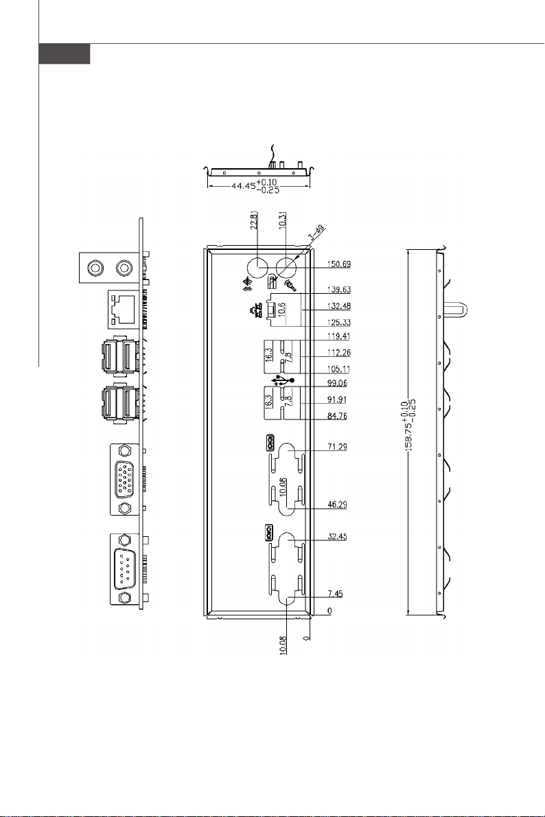
Option A Back Panel
- 1 double stack DB-9 connector
- 1 stack up VGA and DVI-D connector
- 1 stack up RJ45 and USB connector
- 1 double stack USB connector
- 1 Gigabit LAN jack
- 3 audio jacks
Option B Back Panel
- 1 DB-9 connector
- 1 DVI-I connector
- 2 double stack USB connectors
- 1 Gigabit LAN jack
- 2 audio jacks
Option C Back Panel
- 1 DB-9 connector
- 1 VGA connector
- 2 double stack USB connectors
- 1 Gigabit LAN jack
- 2 audio jacks
Option D Back Panel
- 1 DB-9 connector
- 1 stack up VGA and DVI-D connector
- 2 double stack USB connectors
- 1 Gigabit LAN jack
- 2 audio jacks
Option E Back Panel
- 1 DB-9 connector
- 1 VGA connector
- 1 stack up RJ45 and USB connector
- 1 double stack USB connector
- 1 Gigabit LAN jack
- 2 audio jacks
Product Overview
1-3

MS-9830 Mainboard
Onboard Connectors
- 1 front audio pinheader
- 1 USB 2.0 pinheader (2 ports)
- 1 parallel port connector
- 4 serial port connectors (for option A, B, C, E only)
- 1 SPI Flash ROM pinheader (for debugging)
- 1 chassis intrusion switch pinheader
- 1 S/PDIF-Out pinheader
- 1 amplifier pinheader (for option C, E only)
- 1 LVDS connector (for option C, E only)
- 1 20-pin ATX power connector (for option A only)
- 1 4-pin DC 12V power connector (for option B, C, D, E only)
- 1 4-pin DC 5V/12V power connector (for option B, C, D, E only)
Slots
- 1 Mini PCI-E slot
- 1 32-bit/33MHz PCI slot
Form Factor
- Mini ITX: 170mm x 170mm
Mounting
- 4 mounting holes
1-4
Environmental
Storage Environment
- Temperature: -20oC ~ 80oC
- Humidity: 5% ~ 90% non condensing
Operation Environment
- Temperature: 0oC ~ 60oC
- Humidity: 5% ~ 90% non condensing
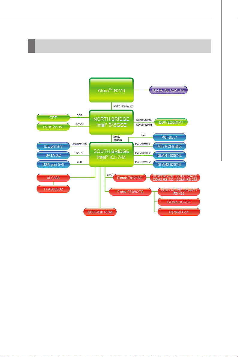
Block Diagram
Product Overview
1-5
MS-9830 Mainboard
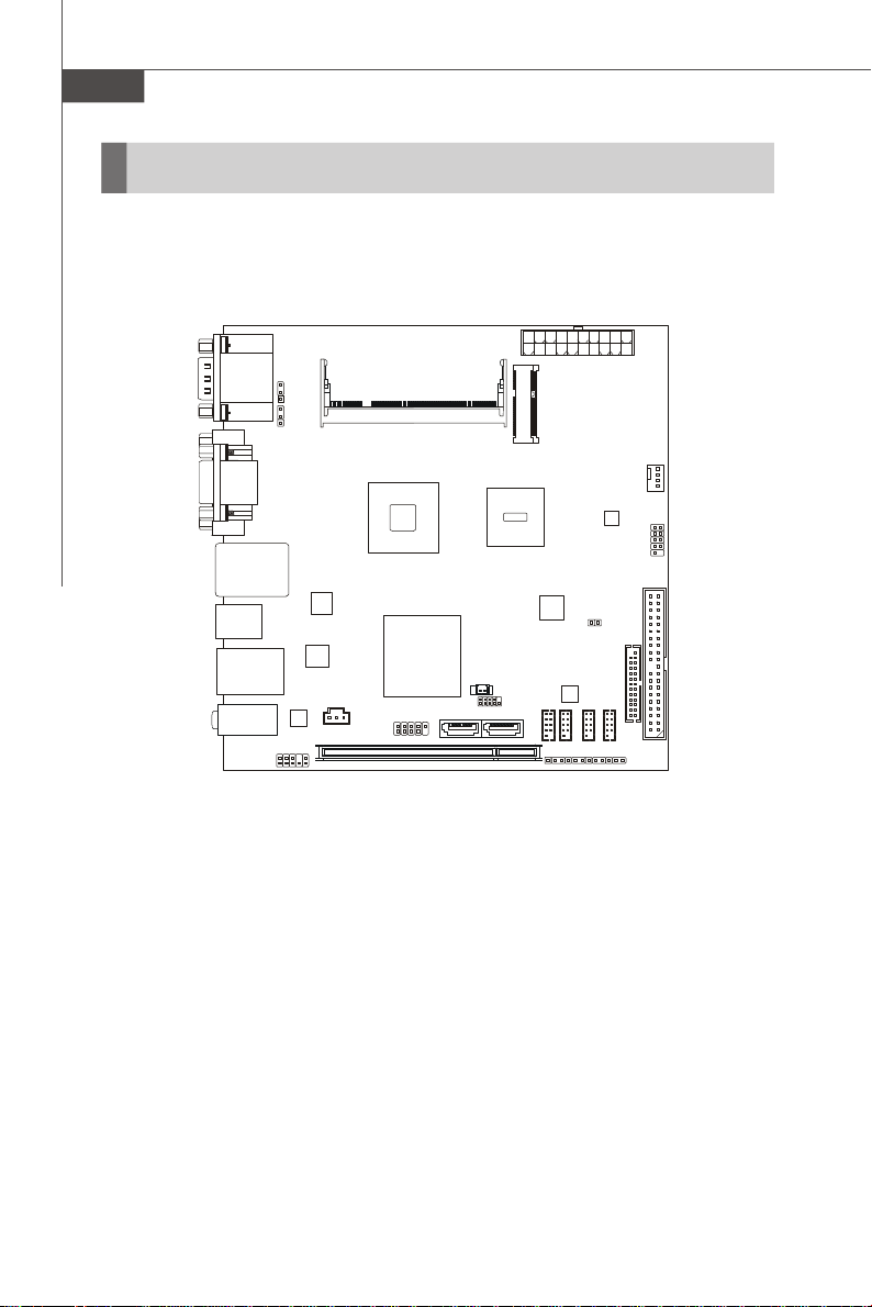
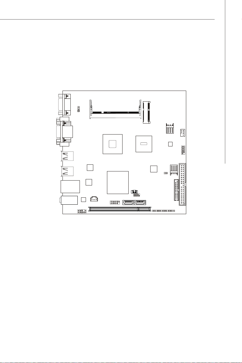
PCI1
COM1COM2COM3COM
4
IDE 1JLPT1CPUFAN1JFP1
ALC888
JSPDO1
2
CON1CON
1
T: Line-In
Mainboard Layout
JCOMP4
JCI1
JCOMP5
ATX1
JCOMP6
COM Ports
Top: VGA Port
Bottom: DVI Port
Top: LAN Jack
Bottom: USB Ports
USB Ports
JLAN1
M: Line-Out
B: Mic-In
JCOMP1
JCOMP
JAUD1
DIMM1
945GSE
Intel
ICH7M
JUSB1
Intel
Atom CPU
JRTC1
SATA1 SATA2
Intel
JSPI1
JCOMP3
IM-945GSE Series Mini ITX Mainboard - Option A
1-6
Product Overview
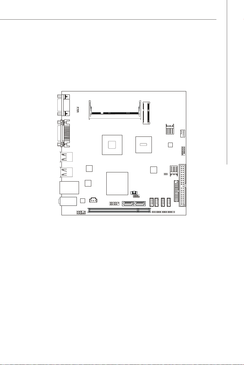
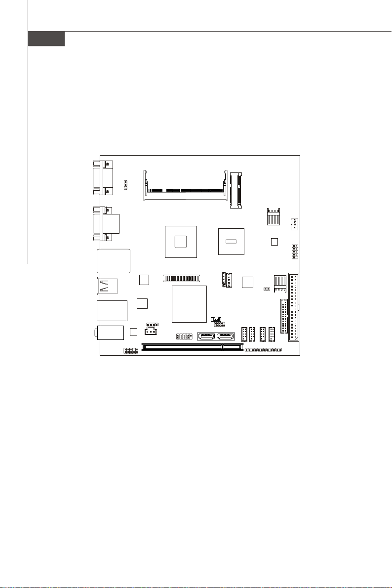
PCI1
IDE 1JLPT1CPUFAN1JFP1
ALC888
JSPDO1
(For HDD)
CON1CON
1
COM5
JCOMP1
JDVI1
USB Ports
USB Ports
DIMM1
Intel 945GSE
Intel Atom CPU
(DC-IN)
JCI1
JPW1
JPWR1
Intel ICH7M
JLAN1
T: Line-Out
B: Mic-In
JUSB1
JAUD1
JRTC1
SATA1 SATA2
JSPI1
COM1
JCOMP3
JCOMP4
COM2
JCOMP5
COM3
JCOMP6
COM4
IM-945GSE Series Mini ITX Mainboard - Option B
1-7
MS-9830 Mainboard
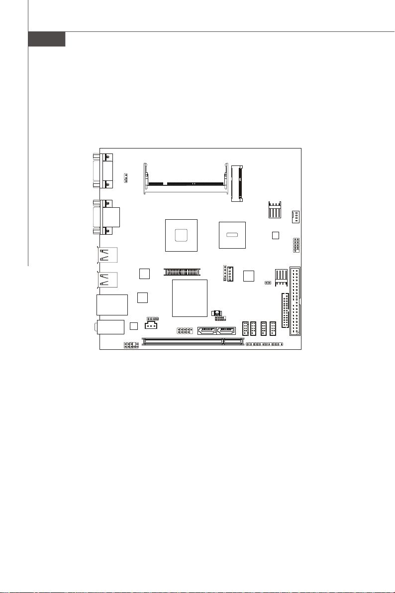
IDE 1JLPT1CPUFAN1JFP1
ALC888
JSPDO1
JLVDS1
JCOMP1
CON1CON
1
Intel Atom CPU
JCOMP3
JCOMP5
COM5
JVGA1
DIMM1
JPW1
(DC-IN)
Intel 945GSE
USB Ports
USB Ports
JVDD1
J1
(For HDD)
JCI1
JPWR1
Intel ICH7M
JLAN1
T: Line-Out
B: Mic-In
JAUD1
JAMP1
JUSB1
PCI1
JRTC1
SATA1 SATA2
JSPI1
COM1
JCOMP4 JCOMP6
COM2
COM3
COM4
IM-945GSE Series Mini ITX Mainboard - Option C
1-8
Product Overview
PCI1
IDE 1JLPT1CPUFAN1JFP1
ALC888
JSPDO1
(For HDD)
CON1CON
1
COM5
JCOMP1
Top: VGA Port
Bottom: DVI Port
USB Ports
USB Ports
DIMM1
Intel 945GSE
Intel Atom CPU
(DC-IN)
JCI1
JPW1
JPWR1
Intel ICH7M
JLAN1
T: Line-Out
B: Mic-In
JAUD1
JUSB1
JRTC1
SATA1 SATA2
JSPI1
JCOMP3
JCOMP4
JCOMP5
JCOMP6
IM-945GSE Series Mini ITX Mainboard - Option D
1-9
MS-9830 Mainboard
IDE 1JLPT1CPUFAN1JFP1
ALC888
JSPDO1
JLVDS1
JCOMP1
CON1CON
1
Intel Atom CPU
JCOMP3
JCOMP5
COM5
JVGA1
DIMM1
JPW1
(DC-IN)
Intel 945GSE
Top: LAN Jack
Bottom: USB Ports
USB Ports
JVDD1
J1
(For HDD)
JCI1
JPWR1
Intel ICH7M
JLAN1
T: Line-Out
B: Mic-In
JAUD1
JAMP1
PCI1
JUSB1
JRTC1
JSPI1
SATA1 SATA2
COM1
JCOMP4 JCOMP6
COM2
COM3
COM4
IM-945GSE Series Mini ITX Mainboard - Option E
1-10
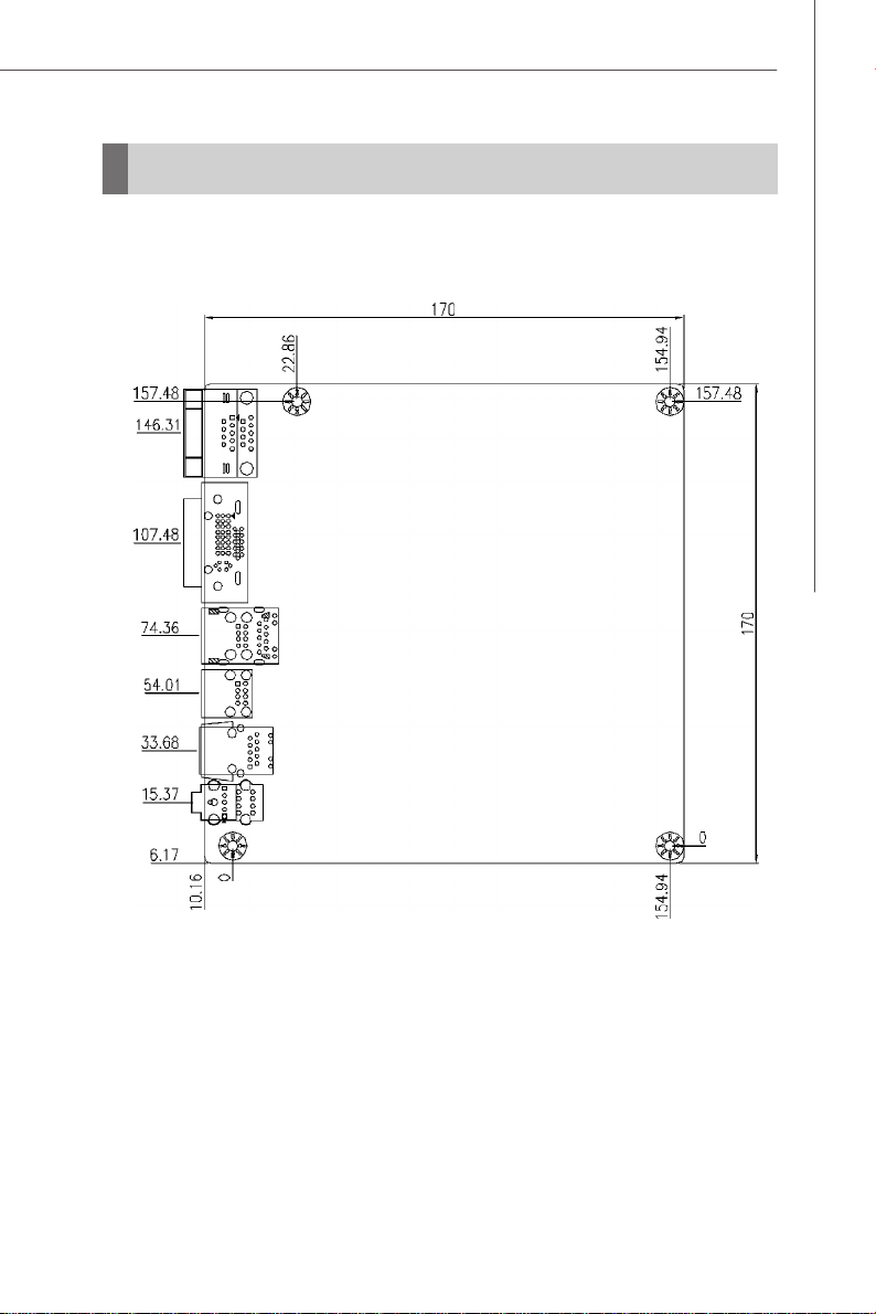
Board Dimension
Product Overview
1-11

MS-9830 Mainboard
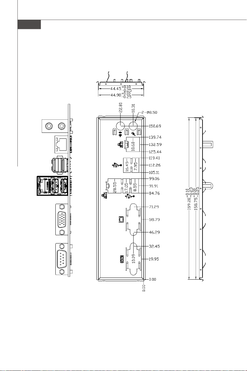
Back Panel & I/O Shield Drawing
1-12
IM-945GSE Series Mini ITX Mainboard - Option A

Product Overview
IM-945GSE Series Mini ITX Mainboard - Option B
1-13
MS-9830 Mainboard
1-14
IM-945GSE Series Mini ITX Mainboard - Option C

Product Overview
IM-945GSE Series Mini ITX Mainboard - Option D
1-15
MS-9830 Mainboard
1-16
IM-945GSE Series Mini ITX Mainboard - Option E
Product Overview
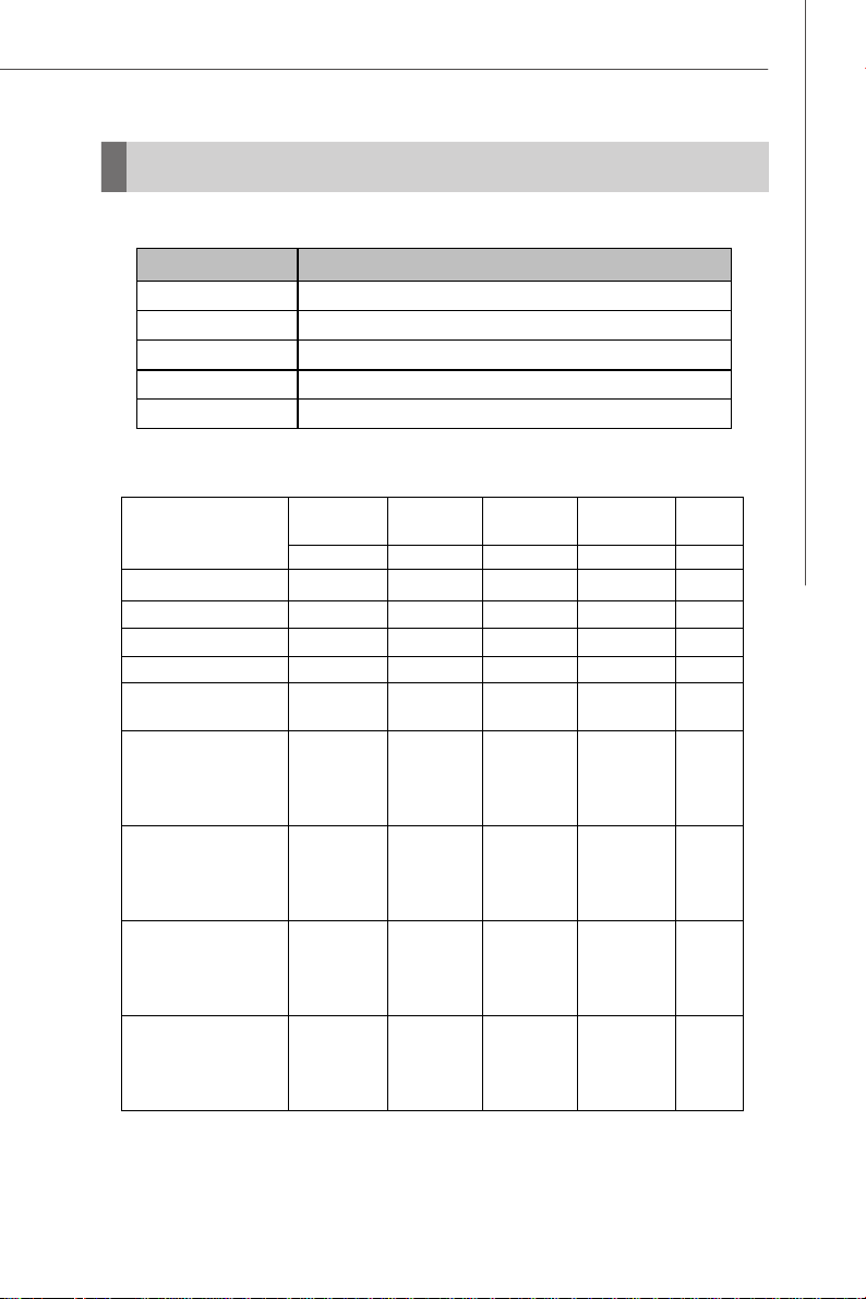
Power Consumption
Component Description
CPU Intel Atom Processor 200 Series
Memory Corsair 1G DDR2-800 x1
Add-On VGA NA
Hard Disk Western 80G IDE 7200rpm HDD x1
Operating System Microsoft Windows XP Professional SP2
Total
Watt
MS-9830-0A (ATX)
Enter DOS (stable)
3.3V input 5V input 12V input 5VSB
Current (A) Current (A) Current (A) Current (A) Watt
0.54 1.03 0.30 0.06 10.83W
Enter BIOS (stable) 0.56 1.03 0.30 0.06 10.90W
Idle
CPU Stress 100%
Windows stress
(3dMARK2006)
0.54 1.10 0.27 0.05 10.77W
0.54 1.18 0.31 0.05 11.65W
0.55 1.11 0.36 0.05 11.94 W
Windows Desktop
Standby S1 without
LAN connected
0.48 1.03 0.25 0.05 9.98W
(stable)
Windows Desktop
Standby S3 without
LAN connected
0 0 0 0.22 1.10W
(stable)
Windows Desktop
Hibernate S4 without
LAN connected
0 0 0 0.13 0.65W
(stable)
Windows Desktop
Soft Off S5 without
LAN connected
0 0 0 0.15 0.75W
(stable)
1-17
 Loading...