


MSI
MICRO-STAR INTERNATIONAL
MS-6534 Micro ATX Mainboard
Version 1.0
G52-MA00417
i

Manual Rev: 1.0
Release Date: August 2001
FCC-B Radio Frequency Interference Statement
This equipment has been tested and found to comply with the limits for a class B digital device, pursuant to part 15 of the FCC rules. These limits are designed to provide reasonable protection against harmful interference when the equipment is operated in a commercial environment. This equipment generates, uses and can radiate radio frequency energy and, if not installed and used in accordance with the instruction manual, may cause harmful interference to radio communications. Operation of this equipment in a residential area is likely to cause harmful interference, in which case the user will be required to correct the interference at his own expense.
Notice 1
The changes or modifications not expressly approved by the party responsible for compliance could void the user's authority to operate the equipment.
Notice 2
Shielded interface cables and A.C. power cord, if any, must be used in order to comply with the emission limits.
VOIR LA NOTICE D'INSTALLATION AVANT DE RACCORDER AU RESEAU.
Micro-Star International MS-6534
Tested to comply with FCC Standard
For Home or Office Use
ii
Edition
August 2001
Copyright Notice
The material in this document is the intellectual property of MICROSTAR INTERNATIONAL. We take every care in the preparation of this document, but no guarantee is given as to the correctness of its contents. Our products are under continual improvement and we reserve the right to make changes without notice.
Trademarks
All trademarks used in this manual are the property of their respective owners.
Intel and Pentium are registered trademarks of Intel Corporation. PS/2 and OS/2 are registered trademarks of IBM Corporation.
Windows 98/2000/ME and Windows NT are registered trademarks of Microsoft. Netware is a registered trademark of Novell.
Award is a registered trademark of Award Software Inc. AMI is a registered trademark of American Megatrends. Inc.
Revision History
Revision |
Revision History |
Date |
1.0 |
First Release |
August 2001 |
iii

Safety Instructions
1.Always read the safety instructions carefully.
2.Keep this User’s Manual for future reference.
3.Keep this equipment away from humidity.
4.Lay this equipment on a reliable flat surface before setting it up.
5.The openings on the enclosure are for air convection hence protects the equipment from overheating. DO NOT COVER THE OPENINGS.
6.Make sure the voltage of the power source and adjust properly 110/220V before connecting the equipment to the power inlet.
7.Place the power cord such a way that people can not step on it. Do not place anything over the power cord.
8.Always Unplug the Power Cord before inserting any add-on card or module.
9.All cautions and warnings on the equipment should be noted.
10.Never pour any liquid into the opening that could damage or cause electrical shock.
11.If any of the following situations arises, get the equipment checked by a service personnel:
•The power cord or plug is damaged
•Liquid has penetrated into the equipment
•The equipment has been exposed to moisture
•The equipment has not work well or you can not get it work according to User’s Manual.
•The equipment has dropped and damaged
•If the equipment has obvious sign of breakage
12.DO NOT LEAVE THIS EQUIPMENT IN AN ENVIRONMENT UNCONDITIONED, STORAGE TEMPERATURE ABOVE 600 C (1400F), IT MAY DAMAGE THE EQUIPMENT.
CAUTION: Danger of explosion if battery is incorrectly replaced. Replace only with the same or equivalent type recommended by the manufacturer.
iv
Contents
Chapter 1. Introduction ............................................................... |
1-1 |
Mainboard Specification ............................................................ |
1-2 |
Mainboard Layout ..................................................................... |
1-4 |
Quick Components Guide ......................................................... |
1-5 |
Key Features ............................................................................ |
1-6 |
Chapter 2. Hardware Setup ........................................................ |
2-1 |
Central Processing Unit: CPU ................................................... |
2-2 |
Installing the CPU ............................................................... |
2-2 |
Installing the CPU Fan ........................................................ |
2-3 |
CPU Core Speed Derivation Procedure................................ |
2-4 |
Memory .................................................................................... |
2-5 |
Introduction to SDRAM ....................................................... |
2-5 |
DIMM Modules Combination ............................................... |
2-6 |
Installing DIMM Modules ..................................................... |
2-6 |
Power Supply ............................................................................ |
2-7 |
ATX 20-Pin Power Connector............................................... |
2-7 |
ATX 12V Power Connector: JPW1 ....................................... |
2-8 |
Back Panel ............................................................................... |
2-9 |
Mouse Connector ................................................................ |
2-9 |
Keyboard Connector ......................................................... |
2-10 |
USB Connectors ............................................................... |
2-10 |
Parallel Port Connector ..................................................... |
2-11 |
Serial Port Connectors: COM A & COM B ........................ |
2-12 |
Joystick/Midi Connector .................................................... |
2-12 |
Audio Port Connectors ...................................................... |
2-12 |
Connectors ............................................................................. |
2-13 |
Floppy Disk Drive Connector: FDD1 .................................. |
2-13 |
Hard Disk Connectors: IDE1 & IDE2 ................................. |
2-14 |
Case Connectors: F_P1 & F_P2 ....................................... |
2-15 |
v
Power Saving Switch Connector: JGS1 ............................. |
2-19 |
Wake On LAN Connector: JWOL1 .................................... |
2-19 |
Wake On Ring Connector: JMDM1 (Optional) ................... |
2-20 |
IrDA Infrared Module Connectors: IR1 & IR2 ...................... |
2-21 |
Fan Power Connectors: C_FAN1/S_FAN1 ......................... |
2-22 |
CD-In/Aux Line-In/Modem-In Connector: CD_IN1/AUX_IN1/ |
|
MDM_IN1 .......................................................................... |
2-23 |
USB Front Panel Connectors: USB1 & USB2 ................... |
2-24 |
Front Panel Audio Connector: JAUDIO1 ............................ |
2-25 |
Jumpers .................................................................................. |
2-26 |
Clear CMOS Jumper: JBAT1 ............................................. |
2-26 |
Slots ....................................................................................... |
2-27 |
AGP (Accelerated Graphics Port) Slot .............................. |
2-27 |
PCI Slots .......................................................................... |
2-27 |
CNR (Communication Network Riser) Slot ........................ |
2-27 |
PCI Interrupt Request Routing ........................................... |
2-28 |
Chapter 3. AWARD® BIOS Setup ................................................ |
3-1 |
Entering Setup .......................................................................... |
3-2 |
Control Keys ............................................................................. |
3-2 |
Getting Help .............................................................................. |
3-3 |
The Main Menu ......................................................................... |
3-4 |
Standard CMOS Features ......................................................... |
3-6 |
Advanced BIOS Features .......................................................... |
3-9 |
Advanced Chipset Features .................................................... |
3-13 |
Integrated Peripherals ............................................................. |
3-15 |
Power Management Setup ...................................................... |
3-19 |
PnP/PCI Configurations ........................................................... |
3-23 |
PC Health Status .................................................................... |
3-25 |
Frequency/Voltage Control ...................................................... |
3-26 |
Load Fail-Safe/Optimized Defaults .......................................... |
3-28 |
vi
Set Supervisor/User Password ................................................ |
3-30 |
Save & Exit Setup ................................................................... |
3-32 |
Exit Without Saving................................................................. |
3-33 |
Chapter 4. AMI® BIOS Setup ...................................................... |
4-1 |
Entering Setup .......................................................................... |
4-2 |
Selecting the First Boot Device ................................................. |
4-2 |
Control Keys ............................................................................. |
4-3 |
Getting Help .............................................................................. |
4-4 |
The Main Menu ......................................................................... |
4-5 |
Standard CMOS Setup ............................................................. |
4-7 |
BIOS Features Setup ................................................................ |
4-9 |
Chipset Features Setup .......................................................... |
4-12 |
Power Management Setup ...................................................... |
4-14 |
PNP/PCI Configuration ............................................................ |
4-18 |
Integrated Peripherals ............................................................. |
4-20 |
Hardware Monitor Setup .......................................................... |
4-24 |
Load Optimal/Fail Safe Defaults .............................................. |
4-26 |
Supervisor/User Password ...................................................... |
4-28 |
IDE HDD AUTO Detection ....................................................... |
4-30 |
Save & Exit Setup ................................................................... |
4-31 |
Exit Without Saving................................................................. |
4-32 |
Appendix A. Using 4-/6-channel Audio Function ..................... |
A-1 |
Installing C-Media Drivers ......................................................... |
A-2 |
Hardware Configuration ............................................................ |
A-2 |
Software Configuration.............................................................. |
A-3 |
Glossary ............................................................................................ |
I |
vii

Introduction
|
1 |
|
Introduction |
||
|
Thank you for purchasing the MS-6534 Micro-ATX motherboard. The mainboard, based on Intel® Brookdale (82845) & 82801BA chipsets, is a high-performance computer mainboard designed for Intel® Pentium® 4 processor in the 478 pin package that provides a high-end and professional desktop platform solution.
This chapter includes the following topics: |
|
Mainboard Specification |
1-2 |
Mainboard Layout |
1-4 |
Quick Components Guide |
1-5 |
Key Features |
1-6 |
1-1

Chapter 1
Mainboard Specification
CPU
zSupports Socket478 for Intel® Pentium 4 (FC-PGA2) processor
zSupports 1.3GHz, 1.4GHz and up to 2.xGHz
Chipset
zIntel® Brookdale chipset
-AGP 4x/2x universal slot
-Supports 100MHz FSB
-Supports 400MHz Intel NetBurst micro-architecture bus
zIntel® ICH2 chipset (360 BGA)
-AC’97 Controller Integrated
-2 full IDE channels, up to ATA100
-Low pin count interface for Winbond SIO
Main Memory
zSupports two 168-pin DIMM sockets
zSupports 32MB to 1GB memory using 512Mbit technology
zMax. memory size: 2GB
 Note: As 845 chipset does not properly support the PC100 memory, it is strongly recommended to install PC133 DIMM modules for better system performance and stability. We do not guarantee the system stability when installing PC 100 DIMM modules.
Slots
zOne AGP (Accelerated Graphics Port) 2x/4x 1.5V slot
zThree PCI 2.2 32-bit Master PCI Bus slots
zSupports 3.3v/5v PCI bus Interface
zOne CNR slot
On-Board IDE
zAn IDE controller on the ICH2 chipset provides IDE HDD/CD-ROM with PIO, Bus Master and Ultra DMA66/100 operation modes.
zCan connect up to four IDE devices.
On-Board Peripherals
z On-Board Peripherals include:
1-2
Introduction
-1 floppy port supports 1 FDD with 360K, 720K, 1.2M, 1.44M and 2.88Mbytes.
-2 serial ports (COMA / COMB)
-1 parallel port supports SPP/EPP/ECP mode
-4 USB ports (Rear * 2 / Front * 2)
-PS/2 Keyboard/Mouse connector
-1 Line-In/Line-Out/Mic-In/Game port
H/W Audio (Optional)
zC-mediaCMI8738-6CH-LX
zSupports 6 channel Audio
zAC97 2.1 compliant
S/W Audio
z2-channel Audio Codec
z4-channel Audio Codec (Optional)
zAC97 2.1 compliant
BIOS
zThe mainboard BIOS provides “Plug & Play” BIOS which detects the peripheral devices and expansion cards of the board automatically.
zThe mainboard provides a Desktop Management Interface (DMI) function which records your mainboard specifications.
Dimension
z Micro ATX Form Factor (24.4cm x 22.4cm)
Mounting
z 6 mounting holes
1-3

Chapter 1
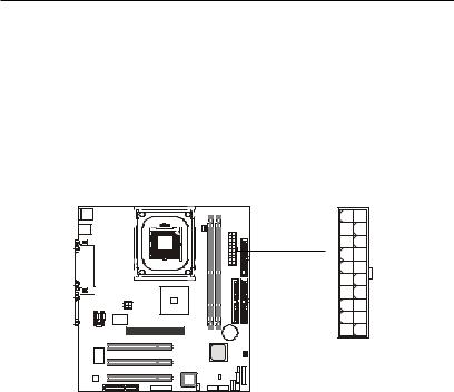
Mainboard Layout
Top : mouse Bottom: keyboard
USB ports |
FAN1 |
|
C_ |
Top : |
Parallel Port |
Bottom:
 COM A
COM A
COM B
|
|
|
|
|
|
|
|
|
|
|
|
|
|
|
|
|
|
|
|
|
|
|
|
|
|
|
|
|
|
|
|
|
|
|
|
|
|
|
|
|
|
JPW1 |
|
|
Intel |
||||||
|
|
|
|
|
|
|
|
|
|
|
|
|
|
|
|
|
|
|
|
|
|||||
|
|
Top : |
|
IN1 |
|
IN1 |
|
|
|
|
Brookdale |
||||||||||||||
|
|
|
|
|
|
|
|
|
|
|
|
|
|
|
|
||||||||||
|
|
Game port_ |
|
AUX |
|
|
|
|
|
|
Chipset |
||||||||||||||
|
|
|
|
Bottom: |
|
CD |
|
|
|
|
|
|
|
|
|
|
|
|
|
||||||
|
|
|
|
|
|
|
|
|
|
|
|
|
|
|
|
|
|||||||||
|
|
|
|
|
|
|
|
|
|
|
|
|
|
|
|
|
|||||||||
|
|
Line-Out |
|
|
|
|
|
|
|
|
|
|
|
|
|
|
|
|
|||||||
|
|
Line-In |
|
|
|
|
|
I/O |
|
|
|
|
|
|
|
|
|
|
|||||||
|
|
Mic |
|
|
|
|
|
Chip |
|
AGP Slot |
|||||||||||||||
|
|
|
|
|
|
|
|
|
|
|
|
|
|
|
|
|
|||||||||
|
|
|
|
|
|
|
|
|
|
MDM_IN1 |
|
|
|
|
|
|
|
|
|
|
|
|
|||
|
|
|
|
|
|
|
|
|
|
|
|
|
|
|
|
|
|
|
|
|
|
|
|
|
|
|
|
|
|
|
|
|
|
|
|
|
|
|
|
|
|
PCI Slot 1 |
|
|
|
|
|
|
|
|
|
|
|
|
|
|
|
|
|
|
|
|
|
|
|
|
|
|
|
|
|
|
|
|
|
|
|
|
|
|
|
|
|
|
|
|
|
H/WAudio |
(Optional) |
|
|
|
|
|
|
|
|
|
|
|
|
|
|
|
|
|
|
|
|
|
|
|
|
|
|
PCI Slot 2 |
|
|
|
|
|
|
|
|
|||||
|
|
|
|
|
|
|
|
|
|
|
|
|
|
|
|
|
|
|
|
|
|
|
|
||
|
|
|
|
|
|
|
|
|
|
|
|
|
|
|
|
|
|
|
|
|
|
|
|
|
|
|
|
|
|
|
|
|
|
|
|
|
|
|
|
|
|
|
|
|
|
|
|
|
|
|
|
|
|
|
|
|
|
Audio Codec |
|
|
PCI Slot 3 |
|
|
|
|
|
|
|
|
||||||||
CNR |
|
FWH |
JAUDIO1 |
JWOL1 |
|
|
|
|
|
|
|
ATX PowerSupply |
|
|
FDD1 |
|
|
|
|
|
|
|
|||
|
|
|
|
|
|
|||
|
|
|
|
|
|
|
|
|
|
|
|
|
|
|
|
|
|
|
|
|
|
|
|
|
|
|
|
|
|
|
|
|
|
|
|
|
|
|
|
|
|
|
|
|
|
|
|
|
|
|
|
|
|
|
|
|
|
|
|
|
|
|
|
|
|
|
|
|
|
|
|
|
|
|
|
|
|
|
|
|
|
|
|
|
|
|
|
|
|
DIMM1 |
DIMM2 |
IDE 2
BATT |
IDE1 |
+ |
|
|
S_FAN1 |
ICH2
JGS1
USB2 USB1
JMDM1 (Optional)
|
JBAT1 |
|
IR1 |
P2 |
P1 |
|
F |
F |

 IR2
IR2
MS-6534 Micro-ATX Mainboard
1-4

|
|
|
Introduction |
|
Quick Components Guide |
|
|
||
|
|
|
|
|
|
Component |
Function |
Reference |
|
|
|
|
|
|
|
DIMM1~2 |
Installing DIMM modules |
See p. 2-5~2-6 |
|
|
|
|
|
|
|
Socket 478 |
Installing CPU |
See p. 2-2~2-4 |
|
|
|
|
|
|
|
C_FAN1 |
Connecting to CPU FAN |
See p. 2-22 |
|
|
|
|
|
|
|
S_FAN1 |
Connecting to SYSTEM FAN |
See p. 2-22 |
|
|
|
|
|
|
|
ATX Power Supply |
Installing power supply |
See p. 2-7 |
|
|
|
|
|
|
|
JPW1 |
Connecting to 12V ATX power supply |
See p. 2-8 |
|
|
|
|
|
|
|
IDE1& IDE2 |
Connecting to IDE hard disk drives |
See p. 2-14 |
|
|
|
|
|
|
|
FDD1 |
Connecting to floppy disk drive |
See p. 2-13 |
|
|
|
|
|
|
|
USB1/2 |
Connecting to USB interfaces |
See p. 2-24 |
|
|
|
|
|
|
|
PCI Slot 1~3 |
Installing PCI expansion cards |
See p. 2-27 |
|
|
|
|
|
|
|
AGP Slot |
Installing AGP cards |
See p. 2-27 |
|
|
|
|
|
|
|
CNR Slot |
Installing CNR cards |
See p. 2-27 |
|
|
|
|
|
|
|
JMDM1 (Optional) |
Connecting to modem module |
See p. 2-20 |
|
|
|
|
|
|
|
JWOL1 |
Connecting to LAN module |
See p. 2-19 |
|
|
|
|
|
|
|
JBAT1 |
Clearing CMOS data |
See p. 2-26 |
|
|
|
|
|
|
|
F_P1/2 |
Connecting to case |
See p. 2-15 |
|
|
|
|
|
|
|
JGS1 |
Connecting to power saving switch |
See p. 2-19 |
|
|
|
|
|
|
|
IR1/2 |
Connecting to IR modules |
See p. 2-21 |
|
|
|
|
|
|
|
JAUDIO1 |
Connecting to front audio connectors |
See p. 2-25 |
|
|
|
|
|
|
1-5

Chapter 1
Key Features
zMicro-ATX Form Factor
zCPU: Socket 478 for Intel® Pentium® 4 Processors
zMemory: 2 SDRAM DIMMs
zSlot: 1 AGP slot, 1 CNR slot, 3 PCI slots
zI/O: 2 serial ports, 1 parallel port, 4 USB 1.1 ports, 1 floppy port, 2 IrDA connectors, 1 Audio/Game port
zPC2001Compliant
zLAN Wake up Function
zModem (External/Internal) Ring Wake up Function (Internal Ring Wake up feature is Optional)
zSTR (Suspend to RAM)
zSuspend to Disk
zAudio: Chip integrated
1-6

Hardware Setup
|
2 |
|
Hardware Setup |
||
|
This chapter provides you with the information about hardware setup procedures. While doing the installation, be careful in holding the components and follow the installation procedures. For some components, if you install in the wrong orientation, the components will not work properly.
Use a grounded wrist strap before handling computer components. Static electricity may damage the components.
This chapter contains the following topics: |
|
Central Processing Unit (CPU) |
2-2 |
Memory |
2-5 |
Power Supply |
2-7 |
Back Panel |
2-9 |
Connectors |
2-13 |
Jumpers |
2-26 |
Slots |
2-27 |
2-1
Chapter 2
Central Processing Unit: CPU
The mainboard supports Intel® Pentium® 4 processor. The mainboard uses a CPU socket called Socket 478 for easy CPU installation. Make sure that the CPU has a Heat Sink and a cooling fan attached to prevent overheating. If you do not find the Heat Sink and cooling fan, contact your dealer or purchase them before turning on the computer.
Installing the CPU
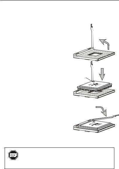
1.Pull the lever sideways away from the socket. Then, raise the lever up to a 90-degree angle.
2.Look for the dot/cut edge. The dot/cut edge should point towards the lever pivot. The CPU will only fit in the correct orientation.
3.Hold the CPU down firmly, and then close the lever to complete the installation.
Open Lever
Sliding
Plate
Dot / Cut edge
Close
Lever
Overheating will seriously damage the CPU
and system, always make sure the cooling fan can work WARNING! properly to protect the CPU from overheating.
2-2
Hardware Setup
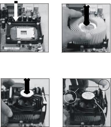
Installing the CPU Fan
As processor technology pushes to faster speeds and higher performance, thermal management becomes increasingly important. To dissipate heat, you need to attach the CPU cooling fan and heatsink on top of the CPU. Follow the instructions below to install the Heatsink/Fan:
1.Locate the CPU and its retention mechanism on the motherboard.
Retention Mechanism
2.Position the heatsink onto the retention mechanism.
3.Mount the fan on top of the heatsink. Press down the fan until its four clips get locked in the holes of the retention mechanism.
4.Press the two levers down to fasten the fan. Each lever can be pressed down in only ONE direction.
Levers
2-3

Chapter 2
5. Connect the fan power cable to the 3-pin fan power connector on the board.
fan power cable
CPU Core Speed Derivation Procedure
If |
CPUClock |
= |
100MHz |
then |
Core/Bus ratio |
= |
14 |
CPU core speed |
= |
Host Clock x Core/Bus ratio |
|
|
|
= |
100MHzx14 |
|
|
= |
1.4GHz |
Overclocking
This motherboard is designed to support overclocking.
However, please make sure your components are able to WARNING! tolerate such abnormal setting, while doing overclocking.
Any attempt to operate beyond product specifications is not recommended. We do not guarantee the damages or risks caused by inadequate operation or beyond product specifications.
2-4
Hardware Setup
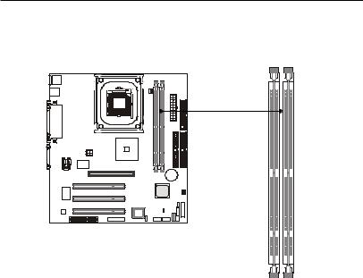
Memory
The mainboard provides 2 sockets for 168-pin SDRAM DIMM (Double In-Line Memory Module) modules and supports a maximum memory size of 2GB.
DIMM Slots
(DIMM 1~2)
Introduction to SDRAM
Synchronous DRAM (SDRAM) is a type of dynamic RAM memory chip that has been widely used starting in the latter part of the 1990s. SDRAMs are based on standard dynamic RAM chips, but have sophisticated features that make them considerably faster. First, SDRAM chips are fast enough to be synchronized with the CPU's clock, which eliminates wait states. Second, the SDRAM chip is divided into two cell blocks, and data is interleaved between the two so that while a bit in one block is being accessed, the bit in the other is being prepared for access. This allows SDRAM to burst the second and subsequent, contiguous characters at a rate of 10ns, compared to 60ns for the first character.
SDRAM provides 800 MBps or 1 GBps data transfer depending on whether the bus is 100MHz or 133MHz.
2-5
Chapter 2
DIMM Modules Combination
You can install memory modules in any combination as follows:
|
DIMM 1 |
DIMM 2 |
|
|
|
|
|
|
S/D |
-- |
|
|
|
|
|
S (Single Side): 32MB ~ 512MB |
-- |
S/D |
|
|
|
||
S |
D |
||
D (Double Side): 64MB ~ 1GB |
|||
|
|
|
|
|
D |
S |
|
|
|
|
|
|
S |
S |
|
|
|
|
|
|
D |
D |
|
|
|
|
 Note: As 845 chipset does not properly support the PC100 memory, it is strongly recommended to install PC133 DIMM modules for better system performance and stability. We do not guarantee the system stability when installing PC 100 DIMM modules.
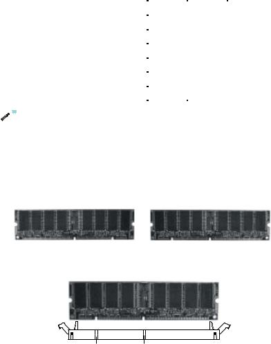
Installing DIMM Modules
1.The DIMM slot has 2 Notch Keys “VOLT and DRAM”, so the DIMM memory module can only fit in one direction.
Front View |
Rear View |
2.Insert the DIMM memory module vertically into the DIMM slot. Then push it in.
DRAM VOLT
3.The plastic clip at each side of the DIMM slot will automatically close.
2-6
Hardware Setup
Power Supply
The mainboard supports ATX power supply for the power system. Before inserting the power supply connectors, always make sure that all components are installed properly to ensure that no damage will be caused.
ATX 20-Pin Power Connector
This connector allows you to connect to an ATX power supply. To connect to the ATX power supply, make sure the plug of the power supply is inserted in the proper orientation and the pins are aligned. Then push down the power supply firmly into the connector.
10 |
20 |
1 |
11 |
ATX
Power Connector
PIN |
SIGNAL |
PIN |
SIGNAL |
1 |
3.3V |
11 |
3.3V |
2 |
3.3V |
12 |
-12V |
3 |
GND |
13 |
GND |
4 |
5V |
14 |
PS_ON |
5 |
GND |
15 |
GND |
6 |
5V |
16 |
GND |
7 |
GND |
17 |
GND |
8 |
PW_OK |
18 |
-5V |
9 |
5V_SB |
19 |
5V |
10 |
12V |
20 |
5V |
2-7
Chapter 2
ATX 12V Power Connector: JPW1
Attaching the ATX power supply to the connector is helpful for offering sufficient voltage to Pentium 4 CPU.
4 2
3 |
1 |
JPW1
PIN |
SIGNAL |
|
1 |
GND |
|
2 |
GND |
|
3 |
12V |
|
4 |
12V |
|
2-8
Hardware Setup
Back Panel
The Back Panel provides the following connectors:
Mouse |
|
Parallel |
|
Midi/Joystick |
Keyboard |
USB |
COM A |
COM B |
L-out L-in MIC |
Mouse Connector
The mainboard provides a standard PS/2® mouse mini DIN connector for attaching a PS/2® mouse. You can plug a PS/2® mouse directly into this connector.
|
|
|
Pin Definition |
||
6 |
5 |
PIN |
SIGNAL |
DESCRIPTION |
|
1 |
Mouse DATA |
Mouse DATA |
|||
|
|
||||
4 |
3 |
2 |
NC |
No connection |
|
3 |
GND |
Ground |
|||
|
1 |
||||
2 |
4 |
VCC |
+5V |
||
PS/2 Mouse (6-pin Female) |
5 |
Mouse Clock |
Mouse clock |
||
6 |
NC |
No connection |
|||
|
|
||||
2-9
Chapter 2
Keyboard Connector
The mainboard provides a standard PS/2® keyboard mini DIN connector for attaching a PS/2® keyboard. You can plug a PS/2® keyboard directly into this connector.
|
|
|
Pin Definition |
||
|
|
PIN |
SIGNAL |
DESCRIPTION |
|
6 |
5 |
1 |
Keyboard DATA |
Keyboard DATA |
|
2 |
NC |
No connection |
|||
4 |
3 |
3 |
GND |
Ground |
|
4 |
VCC |
+5V |
|||
|
|
||||
2 |
1 |
5 |
Keyboard Clock |
Keyboard clock |
|
PS/2 Keyboard (6-pin Female) |
6 |
NC |
No connection |
||
|
|
|
|||
USB Connectors
The mainboard provides a UHCI (Universal Host Controller Interface) Universal Serial Bus root for attaching USB devices such as keyboard, mouse or other USB-compatible devices. You can plug the USB device directly into ths connector.
|
|
|
|
|
|
|
|
|
|
|
|
|
|
|
|
USB Port Description |
|
|
|
|
|
|
|
|
|
|
|
|
|
|
|
|
PIN |
SIGNAL |
DESCRIPTION |
|
1 |
2 |
3 |
4 |
|
|
|
||||||||||
|
|
|
|
|
|
|
|
|
|
|
|
|
|
|
1 |
VCC |
+5V |
|
|
|
|
|
|
|
|
|
|
|
|
|
|
||||
|
|
|
|
|
|
|
|
|
|
|
|
|
|
|
2 |
-Data 0 |
Negative Data Channel 0 |
|
5 |
6 |
7 |
8 |
|
|
|
|
3 |
+Data0 |
Positive Data Channel 0 |
||||||
|
|
|
|
|
4 |
GND |
Ground |
||||||||||
|
|
|
|
|
|
|
|
|
|
|
|
|
|
|
5 |
VCC |
+5V |
|
|
|
|
|
|
|
|
|
|
|
|
|
|
||||
|
|
|
|
|
|
|
|
|
|
|
|
|
|
|
6 |
-Data 1 |
Negative Data Channel 1 |
|
|
|
|
|
|
|
|
|
|
|
|
|
|
||||
|
|
|
|
|
|
|
|
|
|
|
|
|
|
|
7 |
+Data 1 |
Positive Data Channel 1 |
|
|
|
|
|
|
|
|
|
|
|
|
|
|
||||
|
|
|
USB Ports |
||||||||||||||
|
|
|
|
8 |
GND |
Ground |
|||||||||||
2-10

Hardware Setup
Parallel Port Connector
The mainboard provides a 25-pin female centronic connector for LPT. A parallel port is a standard printer port that supports Enhanced Parallel Port (EPP) and Extended Capabilities Parallel Port (ECP) mode.
13 |
1 |
25 |
14 |
Pin Definition
PIN |
SIGNAL |
DESCRIPTION |
1 |
STROBE |
Strobe |
2 |
DATA0 |
Data0 |
3 |
DATA1 |
Data1 |
4 |
DATA2 |
Data2 |
5 |
DATA3 |
Data3 |
6 |
DATA4 |
Data4 |
7 |
DATA5 |
Data5 |
8 |
DATA6 |
Data6 |
9 |
DATA7 |
Data7 |
10 |
ACK# |
Acknowledge |
11 |
BUSY |
Busy |
12 |
PE |
Paper End |
13 |
SELECT |
Select |
14 |
AUTOFEED# |
Automatic Feed |
15 |
ERR# |
Error |
16 |
INIT# |
Initialize Printer |
17 |
SLIN# |
Select In |
18 |
GND |
Ground |
19 |
GND |
Ground |
20 |
GND |
Ground |
21 |
GND |
Ground |
22 |
GND |
Ground |
23 |
GND |
Ground |
24 |
GND |
Ground |
25 |
GND |
Ground |
2-11
Chapter 2
Serial Port Connectors: COM A & COM B
The mainboard has two 9-pin male DIN connectors for serial port COM A and COM B. You can attach a serial mouse or other serial devices.
1 |
2 |
3 |
4 |
5 |
6 7 8 9
9-Pin Male DIN Connectors
Pin Definition
PIN |
SIGNAL |
DESCRIPTION |
1 |
DCD |
Data Carry Detect |
2 |
SIN |
Serial In or Receive Data |
3 |
SOUT |
Serial Out or Transmit Data |
4 |
DTR |
Data Terminal Ready) |
5 |
GND |
Ground |
6 |
DSR |
Data Set Ready |
7 |
RTS |
Request To Send |
8 |
CTS |
Clear To Send |
9 |
RI |
Ring Indicate |
Joystick/Midi Connector
You can connect a joystick or game pad to this connector.
Audio Port Connectors
Line Out is to connect speakers or headphones. Line In is a connector for external CD player, Tape player or other audio devices. Mic is used to connect to a microphone.
Line Out Line In MIC


 The mainboard provides 6-channel audio support and can turn the TIP rear audio connectors from 2-channel to 4-/6-channel audio. For more information, refer to Appendix A. Using 4-/6-channel Audio
Function.
2-12
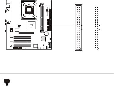
Hardware Setup
Connectors
The mainboard provides connectors to connect FDD, IDE HDD, case, modem, LAN, USB Ports, IR module and CPU/System FAN.
Floppy Disk Drive Connector: FDD1
The mainboard provides a standard floppy disk drive connector that supports 360KB, 720KB, 1.2MB, 1.44MB and 2.88MB floppy disk types.
34 33
2 |
1 |
FDD1 |
|
2-13
Chapter 2
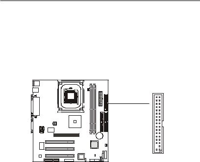
Hard Disk Connectors: IDE1 & IDE2
The mainboard uses an IDE controller on the Intel® ICH2 chipset that provides PIO mode 0-4, Bus Master, and Ultra DMA 66/100 modes. It has two HDD connectors IDE1 (Primary) and IDE2 (Secondary). You can connect up to four hard disk drives, CD-ROM or 120MB Floppy to IDE1 and IDE2.
IDE1 (Primary IDE Connector)
- The first hard disk drive should always be connected to IDE1. You can connect a Master and a Slave drive to IDE1.
IDE2 (Secondary IDE Connector)
- You can connect a Master and a Slave drive to IDE2.
40 39
2 |
1 |
40 39
Secondary IDEConnector |
|
|
|
|
|
Primary IDE Connector |
|
|
|
|
|
||
|
|
|
|
|
||
|
|
|
|
|
||
|
|
|
|
|
|
|
2 |
1 |
|
|
|||
If you install two hard disks on cable, you must configure the 

 second drive to Slave mode by setting its jumper. Refer to the TIP hard disk documentation supplied by hard disk vendors for
jumper setting instructions.
2-14
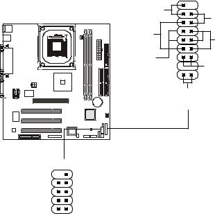
Hardware Setup
Case Connectors: F_P1 & F_P2
The case connector block F_P1 allows you to connect to the Power Switch, Reset Switch, Speaker, Power LED, Keylock and HDD LED on the case.
The other case connector block F_P2 is compliant to Intel Front Panel I/O Connectivity Design Guide and can connect to the the Power Switch, Reset Switch, Power LED and HDD LED on the case.
|
18 |
9 |
Reset |
|
|
Switch |
|
Power |
|
15 |
Switch |
Speaker |
+ |
|
14 |
Power |
|
|
LED |
|
|
|
|
Buzzer |
|
+ |
(short pin) |
|
|
|
|
HDD LED |
|
10 |
1 |
|
Keylock |
|
|
F_P1 |
|
|
|
|
|
|
|
|
|
|
|
10 |
9 |
|
|
|
|
|
|
|
|
|
||
|
|
Power |
|
|
|
|
|
|
|
|
|
|
Reserved |
|
|
|
|
|||||
|
|
|
|
|
|
|
|
|
|
|
|
|
|
|
||||||||
|
|
|
|
|
|
|
|
|
|
|
Reset |
|
|
|
|
|||||||
|
|
Switch |
|
|
|
|
|
|
|
|
|
|
Switch |
|
|
|
|
|||||
|
|
Power |
|
|
|
|
|
|
|
|
|
HDD |
|
|
|
|
||||||
|
|
LED |
|
|
|
|
|
|
|
|
|
|
LED |
F_P1 Pin Definition |
|
|||||||
|
|
|
|
2 |
1 |
|
|
|||||||||||||||
|
|
|
|
|
|
|
|
|
|
|
|
|
|
|
|
|||||||
|
|
|
|
|
|
|
|
|
|
|
|
|
|
|
|
|
|
|
||||
|
|
|
|
|
|
|
|
|
|
F_P2 |
|
|
|
Pin |
Description |
Pin |
|
Description |
||||
|
|
|
|
|
|
|
|
|
|
|
|
|
|
|
|
|
|
1 |
Keylock |
10 |
|
Keylock |
|
F_P2 Pin Definition |
|
|
|
|
|
|
|
|
2 |
NC |
11 |
|
NC |
||||||||
Pin |
Description |
|
Pin |
|
Description |
|
|
|
3 |
HDD_LED+ |
12 |
|
HDD_LED- |
|||||||||
1 |
*HDD_LED+ |
|
2 |
|
|
|
|
|
|
PWR_LED G |
|
|
|
4 |
GND |
13 |
|
CASE_SPK |
||||
3 |
HDD_LED- |
|
4 |
|
|
|
|
|
|
PWR_LED Y |
|
|
5 |
PWR_LED Y |
14 |
|
CASE_SPK |
|||||
5 |
RESET- |
|
6 |
|
|
|
|
|
|
PWR_SW+ |
|
|
6 |
PWR_LED G |
15 |
|
CASE_SPK |
|||||
7 |
RESET+ |
|
8 |
|
|
|
|
|
|
PWR_SW- |
|
|
7 |
PWR_SW+ |
16 |
|
CASE_SPK |
|||||
9 |
RSVD_DNU |
|
10 |
|
|
|
|
NC |
|
|
|
|
|
8 |
PWR_SW- |
17 |
|
RESET+ |
||||
|
|
|
|
|
|
9 |
NC |
18 |
|
RESET- |
||||||||||||
* Hard disk LED pullup (330 ohm) to +5V |
|
|
|
|
||||||||||||||||||
2-15
Chapter 2
Power Switch
Connect to a 2-pin push button switch.
Reset Switch
Reset switch is used to reboot the system rather than turning the power ON/ OFF. Avoid rebooting while the HDD is working. You can connect the Reset switch from the system case to this pin.
Power LED (F_P1)
The Power LED is lit while the system power is on. There are three types of LEDs you can connect from the system case to the pin:
2-pin single color power LED: Connected to pin 5 & 6. The power LED is not able to change its color. You can only choose Blinking in the BIOS utility for the power LED to indicate the suspend/sleep mode.
LEDStatus |
Description |
|
|
Steady Green |
The system is in the full-on mode. |
|
|
Blinking |
The system enters the suspend/sleep mode. |
|
|
2-pin/3-pin dual color power LED: 2-pin LED is connected to pin 5 & 6. 3-pin LED is connected to pin 4, 5 & 6. The dual color power LED is able to change its color to indicate different system states.
Therefore, you can select either Blinking or Dual (color) for the power LED to show the suspend/sleep mode.
z When you select Blinking in the BIOS utility:
LEDStatus |
Description |
|
|
Steady Green |
The system is in the full-on mode. |
|
|
Blinking |
The system enters the suspend/sleep mode. |
|
|
2-16
Hardware Setup
z When you select Dual (color) in the BIOS utility:
LEDStatus |
Description |
|
|
Steady Green |
The system is in the full-on mode. |
|
|
Steady Orange |
The system enters the suspend/sleep mode. |
|
|
Power LED (F_P2)
The Power LED is lit while the system power is on. There are two types of LEDs you can connect from the system case to the pin:
2-pin single color power LED: The power LED is not able to change its color. Therefore, you can only choose Blinking in the BIOS utility for the power LED to indicate the suspend/sleep mode.
LEDStatus |
Description |
|
|
Steady Green |
The system is in the full-on mode. |
|
|
Blinking |
The system enters the suspend/sleep mode. |
|
|
2-pin dual color power LED: The 2-pin power LED can change its color to indicate different system states. Therefore, you can select either Blinking or Dual (color) for the power LED to show the suspend/sleep mode.
z When you select Blinking:
LEDStatus |
Description |
|
|
Steady Green |
The system is in the full-on mode. |
|
|
Blinking |
The system enters the suspend/sleep mode. |
|
|
z When you select Dual (color): |
|
|
|
LEDStatus |
Description |
|
|
Steady Green |
The system is in the full-on mode. |
|
|
Steady Orange |
The system enters the suspend/sleep mode. |
|
|
2-17
 Loading...