


 Loading...
GM338/GM398
Mobile Radios
Basic Service Manual
6804112J17-D
June, 2002

Computer Software Copyrights
The Motorola products described in this manual may include copyrighted Motorola computer programs stored in semiconductor memories or other media. Laws in the United States and other countries preserve for Motorola certain exclusive rights for copyrighted computer programs, including the exclusive right to copy or reproduce in any form, the copyrighted computer program. Accordingly, any copyrighted Motorola computer programs contained in the Motorola products described in this manual may not be copied or reproduced in any manner without the express written permission of Motorola. Furthermore, the purchase of Motorola products shall not be deemed to grant, either directly or by implication, estoppel or otherwise, any license under the copyrights, patents or patent applications of Motorola, except for the normal non-exclusive royalty-free license to use that arises by operation of law in the sale of a product.

i
SAFETY INFORMATION
SAFETY AND GENERAL INFORMATION
Information and Instructions on RF Energy Exposure and Product Safety
READ THIS IMPORTANT INFORMATION ON SAFE AND EFFICIENT OPERATION BEFORE INSTALLING AND USING YOUR MOTOROLA MOBILE TWO-WAY RADIO IN A VEHICLE OR AS A CONTROL STATION.
Compliance with RF Energy Exposure Standards
Your Motorola two-way radio is designed and tested to comply with a number of national and international standards and guidelines (listed below) regarding human exposure to radio frequency electromagnetic energy. This radio complies with the IEEE (FCC) and ICNIRP exposure limits at duty cycles of up to 50% talk-50% listen and should be used for occupational use only. In terms of measuring RF energy for compliance with the FCC exposure guidelines, your radio radiates measurable RF energy only while it is transmitting (during talking), not when it is receiving (listening) or in standby mode.
Your Motorola two-way radio complies with the following RF energy exposure standards and guidelines:
•United States Federal Communications Commission, Code of Federal Regulations; 47CFR part 2 sub-part J
•American National Standards Institute (ANSI) / Institute of Electrical and Electronic Engineers (IEEE) C95. 1-1992
•Institute of Electrical and Electronic Engineers (IEEE) C95.1-1999 Edition
•International Commission on Non-Ionizing Radiation Protection (ICNIRP) 1998
•Ministry of Health (Canada) Safety Code 6. Limits of Human Exposure to Radio frequency Electromagnetic Fields in the Frequency Range from 3 kHz to 300 GHz, 1999
•Australian Communications Authority Radiocommunications (Electromagnetic Radiation - Human Exposure) Standard 2001
•ANATEL, Brazil Regulatory Authority, Resolution 256 (April 11, 2001) "additional requirements for SMR, cellular and PCS product certification."
Operational Instructions and Training Guidelines
To ensure optimal performance and compliance with the RF energy exposure limits in the above standards and guidelines, users should transmit no more than 50% of the time and always adhere to the following procedures:
Transmit and Receive
•To transmit (talk), push the Push-To-Talk (PTT) button; to receive, release the PTT button.
•Transmit only when people outside the vehicle are at least the minimum lateral distance away, as shown in Table 1, from a properly installed, externally-mounted antenna.

ii |
SAFETY INFORMATION |
|
|
Table 1 lists the minimum lateral distance for bystanders in an uncontrolled environment from the transmitting antenna at several different ranges of rated radio power for mobile radios installed in a vehicle.
Table 1: Rated Power and Lateral Distance
Rated Power of Vehicle-Installed |
Minimum Lateral Distance |
|
from Transmitting |
||
Mobile Two-way Radio |
||
Antenna |
||
|
||
|
|
|
Less than 7 watts |
8 inches (20 centimeters) |
|
|
|
|
7 to 15 watts |
1 foot (30 centimeters) |
|
|
|
|
16 to 50 watts |
2 feet (60 centimeters) |
|
|
|
|
51 to 110 watts |
3 feet (90 centimeters) |
|
|
|
Mobile Antennas
•Install antennas at the center of the roof or the center of the trunk deck. These mobile antenna installation guidelines are limited to metal body vehicles.
•The antenna installation must additionally be in accordance with:
a.The requirements of the antenna manufacturer/supplier
b.Instructions in the Radio Installation Manual
•Use only Motorola approved supplied antenna or Motorola approved replacement antenna. Unauthorized antennas, modifications, or attachments could damage the radio and may violate FCC regulations.
Approved Accessories
For a list of approved Motorola accessories please contact your dealer, or local Motorola representative.
Fixed Site Antennas
If mobile radio equipment is installed at a fixed location and operated as a control station or as a fixed unit, the antenna installation must comply with the following requirements in order to ensure optimal performance and compliance with the RF energy exposure limits in the above standards and guidelines.
•The antenna should be mounted outside the building on the roof or a tower if at all possible.
•As with all fixed site antenna installations, it is the responsibility of the licensee to manage the site in accordance with applicable regulatory requirements and may require additional compliance actions such as site survey measurements, signage, and site access restrictions in order to insure that exposure limits are not exceeded.
ELECTROMAGNETIC INTERFERENCE/COMPATIBILITY
NOTE Nearly every electronic device is susceptible to electromagnetic interference (EMI) if inadequately shielded, designed, or otherwise configured for electromagnetic compatibility. It may be necessary to conduct compatibility testing to determine if any electronic equipment used in or around vehicles or near fixed antenna sites is sensitive to external RF energy and if any procedures need to be followed to eliminate or mitigate the potential for interaction between the radio transmitter and the equipment or device.

SAFETY INFORMATION |
iii |
|
|
Facilities
To avoid electromagnetic interference and/or compatibility conflicts, turn off your radio in any facility where posted notices instruct you to do so. Hospitals or health care facilities may be using equipment that is sensitive to external RF energy.
Vehicles
To avoid possible interaction between the radio transmitter and any vehicle electronic control modules, for example, ABS, engine, or transmission controls, we recommend that the radio be installed by an experienced installer and that the following precautions be used when installing the radio:
1.Refer to any manufacturer’s instructions or other technical bulletins or recommendations on radio installation.
2.Before installing the radio, determine the location of the electronic control modules and their harnesses in the vehicle.
3.Route all radio wiring, including the antenna transmission line, as far away as possible from the electronic control units and associated wiring.
Driver Safety
Check the laws and regulations on the use of radios in the area where you drive. Always obey them.
When using your radio while driving, please:
•Give full attention to driving and to the road.
•Pull off the road and park before making or answering a call if driving conditions so require.
OPERATIONAL WARNINGS
For Vehicles With an Air Bag
Do not place a mobile radio in the area over an air bag or in the air bag deployment area. Air bags inflate with great force. If a radio is placed in the air bag deployment area and the air bag inflates, the radio may be propelled with great force and cause serious injury to occupants of the vehicle.
!
W A R N I N G
Potentially Explosive Atmospheres
Turn off your radio prior to entering any area with a potentially explosive atmosphere. Sparks in a potentially explosive atmosphere can cause an explosion or fire resulting in bodily injury or even death.
NOTE The areas with potentially explosive atmospheres referred to above include fueling areas such as below decks on boats, fuel or chemical transfer or storage facilities, and areas where the air contains chemicals or particles, such as grain, dust or metal powders. Areas with potentially explosive atmospheres are often but not always posted.
Blasting Caps and Areas
To avoid possible interference with blasting operations, turn off your radio when you are near electrical blasting caps, in a blasting area, or in areas posted: “Turn off two-way radio.” Obey all signs and instructions.
For radios installed in vehicles fuelled by liquefied petroleum gas in the U.S., refer to the (U.S.) National Fire Protection Association standard, NFPA 58, for storage, handling, and/or container information. For a copy of the LP-gas standard, NFPA 58, contact the National Fire Protection Association, One Battery Park, Quincy, MA.
iv |
SAFETY INFORMATION |
|
|
THIS PAGE INTENTIONALLY LEFT BLANK
|
|
|
v |
|
|
||
Table of Contents |
|
||
Section 1 |
Introduction |
|
|
1.0 |
Scope of Manual .................................................................................................. |
1-1 |
|
2.0 |
Warranty and Service Support............................................................................. |
1-1 |
|
2.1 |
Warranty Period and Return Instructions ....................................................... |
1-1 |
|
2.2 |
After Warranty Period ..................................................................................... |
1-1 |
|
2.3 |
Piece Parts Availability ................................................................................... |
1-2 |
|
2.4 |
Technical Support........................................................................................... |
1-2 |
|
3.0 |
Radio Model Information...................................................................................... |
1-3 |
|
Section 2 |
Maintenance |
|
|
1.0 |
Introduction .......................................................................................................... |
2-1 |
|
2.0 |
Preventive Maintenance ...................................................................................... |
2-1 |
|
2.1 |
Inspection ....................................................................................................... |
2-1 |
|
2.2 |
Cleaning Procedures ...................................................................................... |
2-1 |
|
3.0 |
Safe Handling of CMOS and LDMOS Devices .................................................... |
2-2 |
|
4.0 |
Repair Procedures and Techniques — General .................................................. |
2-3 |
|
5.0 |
Disassembling and Reassembling the Radio — General .................................... |
2-3 |
|
6.0 |
Radio Disassembly - Detailed.............................................................................. |
2-4 |
|
6.1 |
Control Head Removal ................................................................................... |
2-4 |
|
6.2 |
Top Cover Removal........................................................................................ |
2-5 |
|
6.3 |
Transceiver Board Removal ........................................................................... |
2-6 |
|
6.4 |
Disassembly of Control Heads ....................................................................... |
2-7 |
|
7.0 |
Radio Assembly ................................................................................................... |
2-9 |
|
7.1 |
Control Heads - GM338 and GM398.............................................................. |
2-9 |
|
7.2 |
Radio Chassis And Transceiver Board........................................................... |
2-9 |
|
7.3 |
Control Head Fitting........................................................................................ |
2-9 |
|
8.0 |
Radio Exploded Mechanical Views and Parts Lists ........................................... |
2-10 |
|
8.1 |
Radio Assembly............................................................................................ |
2-10 |
|
8.2 |
Control Head - GM338 ................................................................................. |
2-11 |
|
8.3 |
Control Head - GM398 ................................................................................. |
2-12 |
|
9.0 |
Service Aids ....................................................................................................... |
2-13 |
|
10.0 |
Test Equipment.................................................................................................. |
2-14 |
|
11.0 |
Programming/Test Cable - RKN4083_ ............................................................. |
2-15 |
|
Section 3 Transceiver Performance Testing
1.0 |
General ................................................................................................................ |
3-1 |
2.0 |
Setup.................................................................................................................... |
3-1 |
3.0 |
RF Test Mode ...................................................................................................... |
3-2 |

vi
Section 4 |
Radio Tuning and Programming |
|
|
1.0 |
Introduction .......................................................................................................... |
4-1 |
|
2.0 |
CPS Programming Setup .................................................................................... |
4-1 |
|
3.0 |
Radio Tuning Setup ............................................................................................. |
4-3 |
|
|
3.1 |
Initial Test Equipment Control Settings .......................................................... |
4-3 |
Section 5 |
Power Up Self-Test |
|
|
1.0 |
Error Codes ......................................................................................................... |
5-1 |
|
Section 6 |
Model Chart and Test Specification |
|
|
1.0 |
Low Power Radios............................................................................................... |
6-1 |
|
|
1.1 |
Model Chart (VHF 136-174 MHz)................................................................... |
6-1 |
|
1.2 |
Model Chart (UHF Band 1, 403-470 MHz) ..................................................... |
6-2 |
|
1.3 |
Model Chart (UHF Band 2, 450-527 MHz) ..................................................... |
6-3 |
|
1.4 |
Model Chart (Low Band, 29.7-50.0 MHz)....................................................... |
6-3 |
|
1.5 |
Specifications ................................................................................................ |
6-4 |
2.0 |
High Power Radios .............................................................................................. |
6-6 |
|
|
2.1 |
Model Chart (VHF 136-174 MHz)................................................................... |
6-6 |
|
2.2 |
Model Chart (UHF Band 1, 403-470 MHz) ..................................................... |
6-6 |
|
2.3 |
Model Chart (UHF Band 2, 450-520 MHz) ..................................................... |
6-7 |
|
2.4 |
Model Chart (UHF Band 1, LDMOS, 403-470 MHz) ...................................... |
6-7 |
|
2.5 |
Model Chart (UHF Band 2, LDMOS, 450-520 MHz) ...................................... |
6-8 |
|
2.6 |
Specifications ................................................................................................ |
6-9 |
Glossary of Terms .................................................................................... |
G-1 |
||

1-1
Section 1
INTRODUCTION
1.0Scope of Manual
This manual is intended for use by service technicians familiar with similar types of equipment. It contains service information required for the equipment described and is current as of the printing date. Changes which occur after the printing date may be incorporated by a complete manual revision or alternatively as additions.
NOTE Before operating or testing these units, please read the Safety Information section in the front of this manual.
2.0Warranty and Service Support
Motorola offers support which includes: full exchange and/or repair of the product during the warranty period; and service/ repair or spare parts support out of warranty. Any “return for exchange” or “return for repair” to an authorized Motorola Dealer must be accompanied by a Warranty Claim Form. Warranty Claim Forms are obtained by contacting an Authorized Motorola Dealer.
2.1Warranty Period and Return Instructions
The terms and conditions of warranty are defined fully in the Motorola Dealer or Distributor or Reseller contract. These conditions may change from time to time, and the following subsections are for guidance purposes only.
In instances where the product is covered under a “return for replacement” or “return for repair” warranty, a check of the product should be performed prior to shipping the unit back to Motorola. This is to ensure that the product has been correctly programmed or has not been subjected to damage outside the terms of the warranty.
Prior to shipping any radio back to the appropriate Motorola warranty depot, please contact Customer Resources. All returns must be accompanied by a Warranty Claim Form, available from your Customer Resources representative. Products should be shipped back in the original packaging, or correctly packaged to ensure that no damage occurs in transit.
2.2After Warranty Period
After the Warranty period, Motorola continues to support its products in two ways:
1.Motorola's Accessories and Aftermarket Division (AAD) offers a repair service to both end users and dealers at competitive prices.
2.AAD supplies individual parts and modules that can be purchased by dealers who are technically capable of performing fault analysis and repair.
1-2 |
Warranty and Service Support |
|
|
2.3Piece Parts Availability
Some replacement parts, spare parts, and/or product information can be ordered directly. If a complete Motorola part number is assigned to the part, it is available from Motorola’s Accessories and Aftermarket Division (AAD). If no part number is assigned, the part is not normally available from Motorola. If the part number is appended with an asterisk, the part is serviceable by Motorola Depot only. If a parts list is not included, this generally means that no user-serviceable parts are available for that kit or assembly.
All orders for parts/information should include the complete Motorola identification number. All part orders should be directed to your local AAD office. Please refer to your latest price pages.
2.4Technical Support
Technical support is available to assist the dealer/distributor in resolving any malfunction which may be encountered. Initial contact should be by telephone wherever possible. When contacting Motorola Technical Support, be prepared to provide the product model number and the unit’s serial number.
Toll-Free
Country or Territory |
Number |
|
|
China |
800-810-0976 |
|
|
Indonesia |
0800-1-686868 |
|
|
Malaysia |
1800-801687 |
|
|
Philippines |
1800-16510271 |
|
|
Singapore |
1800-4855333 |
|
|
Thailand |
1800-225412 |
|
|
Non-Toll-Free |
|
|
|
Country or Territory |
Number |
|
|
China |
(86-10) 6843-8231 |
|
|
Hong Kong SAR |
(852) 2966-4188 |
|
|
India |
(91) 80-658-7677-7678 |
|
|
Indonesia |
(62-21) 251-3050 |
|
|
Korea |
(822) 3466-5401 |
|
|
Malaysia |
(603) 7803-9922 |
|
|
Philippines |
(63-2) 810-0762 |
|
|
Singapore |
(65) 486-7171 |
|
|
Taiwan |
(886) 2-27058000 ext. 6308 |
|
|
Thailand |
(66) 2254-8388 |
|
|
Vietnam |
(84) 8-8294091 |
|
|
All Other Countries |
IDD code + (65) 4855333 |
|
|
1-3 |
Radio Model Information |
|
|
3.0Radio Model Information
The model number and serial number are located on a label attached to the back of your radio. You can determine the RF output power, frequency band, protocols, and physical packages. The example below shows one mobile radio model number and its specific characteristics.
Table 1-1 Radio Model Number (Example: AZM25KHF9AA5)
|
Type of |
Model |
Freq. |
Power |
Physical |
|
Channel |
Protocol |
Feature |
|
|
Unit |
Series |
Band |
Level |
Packages |
|
Spacing |
Level |
||
|
|
|
||||||||
|
|
|
|
|
|
|
|
|
|
|
AZ |
M |
25 |
K |
H |
F |
9 |
AA |
5 |
||
Code |
|
|
|
VHF |
1-25W |
GM338 |
|
Program- |
Conventional |
GM338 |
|
|
|
174MHz) |
|
|
|
mable |
|
|
|
|
|
|
|
(136- |
|
|
|
|
|
|
AZ = Country |
M = Mobile |
|
|
|
|
|
|
|
|
|
|
|
|
|
|
|
|
|
|
|
|
|
|
|
|
R |
K |
N |
|
|
|
8 |
|
|
|
|
UHF1 |
25-60W |
GM398 |
|
|
|
GM398 |
|
|
|
|
(403- |
|
|
|
|
|
|
|
|
|
|
470MHz) |
|
|
|
|
|
|
|
|
|
|
|
|
|
|
|
|
|
|
|
|
|
S |
|
|
|
|
|
|
|
|
|
|
UHF2 |
|
|
|
|
|
|
|
|
|
|
(450- |
|
|
|
|
|
|
|
|
|
|
527MHz) |
|
|
|
|
|
|
|
|
|
|
|
|
|
|
|
|
|
|
|
|
|
B |
|
|
|
|
|
|
|
|
|
|
LB, R1 |
|
|
|
|
|
|
|
|
|
|
(29.7- |
|
|
|
|
|
|
|
|
|
|
36MHz) |
|
|
|
|
|
|
|
|
|
|
|
|
|
|
|
|
|
|
|
|
|
C |
|
|
|
|
|
|
|
|
|
|
LB, R2 |
|
|
|
|
|
|
|
|
|
|
(36- |
|
|
|
|
|
|
|
|
|
|
40MHz) |
|
|
|
|
|
|
|
|
|
|
|
|
|
|
|
|
|
|
|
|
|
D |
|
|
|
|
|
|
|
|
|
|
LB, R3 |
|
|
|
|
|
|
|
|
|
|
(42- |
|
|
|
|
|
|
|
|
|
|
50MHz) |
|
|
|
|
|
|
|
|
|
|
|
|
|
|
|
|
|
1-4 |
Radio Model Information |
|
|
THIS PAGE INTENTIONALLY LEFT BLANK

2-1
Section 2
MAINTENANCE
1.0Introduction
This chapter provides details about the following:
•Preventive maintenance (inspection and cleaning).
•Safe handling of CMOS and LDMOS devices.
•Disassembly and reassembly of the radio.
•Repair procedures and techniques.
2.0Preventive Maintenance
The radios do not require a scheduled preventive maintenance program; however, periodic visual inspection and cleaning is recommended.
2.1Inspection
Check that the external surfaces of the radio are clean, and that all external controls and switches are functional. It is not recommended to inspect the interior electronic circuitry.
2.2Cleaning Procedures
The following procedures describe the recommended cleaning agents and the methods to be used when cleaning the external and internal surfaces of the radio. External surfaces include the front cover, housing assembly and battery case. These surfaces should be cleaned whenever a periodic visual inspection reveals the presence of smudges, grease, and/or grime.
NOTE Internal surfaces should be cleaned only when the radio is disassembled for service or
|
repair. |
|
The only recommended agent for cleaning the external radio surfaces is a 0.5% solution of a mild |
|
dishwashing detergent in water. The only factory recommended liquid for cleaning the printed circuit |
|
boards and their components is isopropyl alcohol (70% by volume). |
|
|
! |
CAUTION: The effects of certain chemicals and their vapors can have harmful results on certain plas- |
tics. Avoid using aerosol sprays, tuner cleaners, and other chemicals. |
|
|
|
|
Cleaning External Plastic Surfaces |
|
Apply the 0.5% detergent-water solution sparingly with a stiff, non-metallic, short-bristled brush to |
|
work all loose dirt away from the radio. Use a soft, absorbent, lintless cloth or tissue to remove the |
|
solution and dry the radio. Make sure that no water remains entrapped near the connectors, cracks, |
|
or crevices. |

2-2 |
Safe Handling of CMOS and LDMOS Devices |
|
|
Cleaning Internal Circuit Boards and Components
Isopropyl alcohol (70%) may be applied with a stiff, non-metallic, short-bristled brush to dislodge embedded or caked materials located in hard-to-reach areas. The brush stroke should direct the dislodged material out and away from the inside of the radio. Make sure that controls or tunable components are not soaked with alcohol. Do not use high-pressure air to hasten the drying process since this could cause the liquid to collect in unwanted places. After completing of the cleaning process, use a soft, absorbent, lintless cloth to dry the area. Do not brush or apply any isopropyl alcohol to the frame, front cover, or back cover.
NOTE Always use a fresh supply of alcohol and a clean container to prevent contamination by dissolved material (from previous usage).
3.0Safe Handling of CMOS and LDMOS Devices
Complementary metal-oxide semiconductor (CMOS) devices are used in this family of radios, and are susceptible to damage by electrostatic or high voltage charges. Damage can be latent, resulting in failures occurring weeks or months later. Therefore, special precautions must be taken to prevent device damage during disassembly, troubleshooting, and repair.
Handling precautions are mandatory for CMOS circuits and are especially important in low humidity conditions. DO NOT attempt to disassemble the radio without first referring to the following CAUTION statement.
CAUTION: This radio contains static-sensitive devices. Do not open the radio unless you are properly
!grounded. Take the following precautions when working on this unit:
•Store and transport all CMOS devices in conductive material so that all exposed leads are shorted together. Do not insert CMOS devices into conventional plastic “snow” trays used for storage and transportation of other semiconductor devices.
•Ground the working surface of the service bench to protect the CMOS device. We recommend using the Motorola Static Protection Assembly (part number 0180386A82), which includes a wrist strap, two ground cords, a table mat, and a floor mat.
•Wear a conductive wrist strap in series with a 100k resistor to ground. (Replacement wrist straps that connect to the bench top covering are Motorola part number RSX4015_).
•Do not wear nylon clothing while handling CMOS devices.
•Do not insert or remove CMOS devices with power applied. Check all power supplies used for testing CMOS devices to be certain that there are no voltage transients present.
•When straightening CMOS pins, provide ground straps for the apparatus used.
•When soldering, use a grounded soldering iron.
•If at all possible, handle CMOS devices by the package and not by the leads. Prior to touching the unit, touch an electrical ground to remove any static charge that you may have accumulated. The package and substrate may be electrically common. If so, the reaction of a discharge to the case would cause the same damage as touching the leads.
Repair Procedures and Techniques — General |
2-3 |
|
|
4.0Repair Procedures and Techniques — General
Parts Replacement and Substitution
When damaged parts are replaced, identical parts should be used. If the identical replacement part is not locally available, check the parts list for the proper Motorola part number and order the part from the nearest Motorola Communications parts center listed in the “Piece Parts” section of this manual.
Rigid Circuit Boards
This family of radios uses bonded, multi-layer, printed circuit boards. Since the inner layers are not accessible, some special considerations are required when soldering and unsoldering components. The printed-through holes may interconnect multiple layers of the printed circuit. Therefore, exercise care to avoid pulling the plated circuit out of the hole.
When soldering near the 20-pin and 40-pin connectors:
•Avoid accidentally getting solder in the connector.
•Be careful not to form solder bridges between the connector pins.
•Examine your work closely for shorts due to solder bridges.
5.0Disassembling and Reassembling the Radio — General
Since these radios may be disassembled and reassembled with the use of only four (board to casting) screws, it is important to pay particular attention to the snaps and tabs, and how parts align with each other.
The following tools are required for disassembling the radio:
•Small flat blade screwdriver
•Dismantling Tool (Motorola Part No. 6686119B01)
•TORX™ T20 screwdriver
If a unit requires more complete testing or service than is customarily performed at the basic level, send this unit to a Motorola Authorized Service Center. (See Chapter 1 for a list of authorized service centers.)
The following disassembly procedures should be performed only if necessary:
2-4 |
Radio Disassembly - Detailed |
|
|
6.0Radio Disassembly - Detailed
The procedure to remove and replace a Control Head, Top Cover or Transceiver Board is similar for all models of radio. A typical procedure is therefore shown followed by specific disassembly procedures for Control Heads on radio models.
6.1Control Head Removal
1.Insert the dismantling tool in the groove between the control head and the radio assembly as shown in Figure 2-1.
2.Press on the dismantling tool until the snap connectors on the side of the control head release from the radio assembly.
Dismantling
Tool
ZWG0130209-O
Figure 2-1 Typical Control Head Removal.
3.Pull the control head away from the radio assembly as shown in Figure 2-2.

Radio Disassembly - Detailed |
2-5 |
|
|
Flexible
Connection
ZWG0130210-O
Figure 2-2 Flexible Connection Removal
4.Remove the flexible connection from the socket on the control head board.
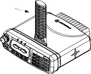
6.2Top Cover Removal
1.Insert the dismantling tool in the middle of the radio assembly side groove as shown in Figure 2-3.
2.Press on the dismantling tool until the snap connectors on the side of the cover release from the radio chassis.
3.Lift the top cover from the chassis.

 Dismantling
Tool
ZWG0130211-O
Figure 2-3 Top Cover Removal.
Loading...