


 Loading...
D C T 2 0 0 0
D i g i t a l C o n s u m e r T e r m i n a l
I n s t a l l a t i o n M a n u a l
CURSOR |
MESSAGES |
|
REMOTE |
CHANNEL |
|
A/B |
|
POWER |
|
GUIDE |
INFO |
MENU |
A/B |
POWER |
|
SELEC T |

Graphical symbols and supplement warning marking loscations on the bottom of the appliance.
This symbol indicates that dangerous voltage levelss are present within the equipment. These voltages asre not insulated and may be of sufficient strength to cause serious bodisly injury when touched. The symbol may also appear son schematics.
This symbol calls attention to a critical procedures, or means refer to the instruction manual for opensing or service information. Only qualified service personnel are tso install or service the equipment. The symbol may salso appear in text and on schematics.
WARNING:
TO PREVENT FIRE OR SHOCK HAZARD, DO NOT EXPOSE THIS APPLIANCE TO RAIN OR MOISTURE.
CAUTION:
TO PREVENT ELECTRICAL SHOCK, DO NOT USE THIS PLUG W ITH AN EXTENSION CORD, RECEPTACLE, OR OTHER OUTLET UNLESS THE BLADES CAN BE FULLY INSERTED TO PREVENT BLADE EXPOSURE.
FCC Compliance: This equipment has been tested and found to complys with the limits for a Class B digital device, pursusant to Part 15 of the FCC Rules. These limits are designed to provide reasonable prostection against harmful interference when the equipsment is operated in a comercial environment. This equipment generates, uses, and can radiate radsio frequency energy and, if not installed and used sin accordance with the stallationIn Manual, may cause harmful interference to radio communications.s Operation of this equipment in a residential area sis likely to cause harmful interference in which case the user will be required to correct the intersference at his own expense. Any changes or modificastions not expressly approved by Motorola could void the user’s authority to operate this equipments under the rules and regulations of the FCC.
Canadian Compliance: This Class B digital apparatus meets all requiremensts of the Canadian Interference-Causing Equipment Regulsations. Cet appareil numérique de la classe B respects toutess les exigences du Règlement sur le matériel brouilleusr du Canada.
Repairs: If repair is necessary, call the Motorola Repsair Facility at 1-800-227-0450 for a Return for Service Authorizastion (RSA) number before sending the unit. The RSA number must be prominently displayesd on all equipment cartons. Pack the unit securely,s enclose a note describing the exact problem, and a copy of the invoice that verifies the warrantsy status. Ship the unit PRE-PAID to the following addresss:
Motorola
Attn: RSA #___________
5964 E. 14th Street
Brownsville, TX 78521
NOTE TO CATV SYSTEM INSTALLER: This reminder is provided to call CATV system instalsler’s attention to Article 820-40 of the NEC that provides guidelines for proper grounding and, in particular,s specifies that the cable ground shall be connecteds to the grounding systemof the building, as close as possible to the point of cable entry as practicasl.
All rights reserved. No part of this publication mays be reproduced in any form or by any means or used sto make any derivativeorkw (such as translation, transformation or adaptation) without written permisssion from General Instrument Corporation.
General Instrument Corporation reserves the right tos revise this publication and to make changes in constent from time to timeithoutw obligation on the part of General Instrument Corporation to provide nostification of such revision or change.
Motorola provides this guide without warranty of ansy kind, either implied or expressed, including, buts not limited, to the implied warranties of merchantability and fitness for a particular purposse. Motorola may make improvements or changes in thes product(s) described inthis manual at any time.
Copyright © 2000 by General Instrument Corporation, a whoslly owned subsidiary of Motorola, Inc.
General Instrument Corporation provides this guide wsithout warranty of any kind, either implied or exprsessed, including, but not limited, to the implied warranties of merchantability and fitness for a parsticular purpose. General Instrument Corporation may smake improvements or changes in the product(s) described in this manual at any time.
 and MOTOROLA are registered trademarks of Motorola, Isnc.
Dolby, AC-3, and Dolby Surround are registered trademarkss of Dolby Laboratories, Inc.
General Instrument is a trademark and STARVUE, and STARFONE sare registered trademarks of General Instrument Corpsoration, a wholly owned subsidiary of Motorola, Inc.

C o n t e n t s
Section 1
I n t r o d u c t i o n
Features and Options ................................................... |
t................................................... |
t........... |
1-1 |
Using This Manual ................................................... |
t................................................... |
t............... |
1-2 |
Related Documentation ................................................... |
t................................................... |
t........ |
1-3 |
Document Conventions ................................................... |
t................................................... |
t......... |
1-3 |
If You Need Help ................................................... |
t................................................... |
t................. |
1-3 |
Calling for Repairs ................................................... |
t................................................... |
t.............. |
1-4 |
Section 2 |
|
|
|
O v e r v i e w |
|
|
|
Front Panel ................................................... |
t................................................... |
t........................ |
2-1 |
Rear Panel ................................................... |
t................................................... |
t......................... |
2-3 |
Options ................................................... |
t................................................... |
t............................. |
2-4 |
Remote Controls ................................................... |
t................................................... |
t................. |
2-6 |
DRC 400 Remote Control ................................................................................................................. |
|
|
2-6 |
Installing Batteries in Remote Control ............................................................................................... |
|
|
2-8 |
Section 3 |
|
|
|
I n s t a l l a t i o n |
|
|
|
Before You Begin................................................... |
t................................................... |
t................. |
3-1 |
Installing the DCT 2000................................................... |
t................................................... |
t........ |
3-1 |
Standard Cabling Diagram ............................ |
t................................................... |
t........................... |
3-2 |
STARFONE module cabling diagram ................................................... |
|
t............................................. |
3-3 |
Standard VCR Cabling Diagram ................................................... |
|
t.................................................. |
3-4 |
RF Bypass Switch VCR Cabling Diagrams ................................................... |
|
t...................................... |
3-5 |
A/B In Module Cabling Diagrams ................................................... |
|
t............................................... |
3-7 |
Dual A/B-RF Bypass Module Cabling Diagrams ................................................... |
t.............................. |
3-9 |
|
Composite Baseband and S-Video Cabling Diagrams ................................................... |
t..................... |
3-11 |
|
Stereo Cabling Diagram (Baseband) ................................................... |
|
t.......................................... |
3-13 |
Dolby Digital Cabling Diagrams................................................... |
|
t................................................ |
3-16 |
Operational Check.................................. |
t................................................... |
t.............................. |
3-18 |
DCT 2000 Installation Manual
i i |
C o n t e n t s |
|
|
Section 4
A d d i n g t h e I R B l a s t e r O p t i o n
Locating the IR Receiver on the VCR ................................................... |
|
t........................................... |
|
4-1 |
Installing the IR Blaster.......................... |
t................................................... |
t................................ |
|
4-2 |
Checking the Installation ................................................... |
|
t................................................... |
......t |
4-2 |
Section 5 |
|
|
|
|
T r o u b l e s h o o t i n g |
|
|
|
|
Appendix A |
|
|
|
|
S p e c i f i c a t i o n s |
|
|
|
|
Appendix B |
|
|
|
|
D i a g n o s t i c s |
|
|
|
|
Accessing Diagnostics ................................................... |
|
t................................................... |
t......... |
B-1 |
Navigating the Diagnostics ................................................... |
|
t....................................................... |
|
B-2 |
d 01: DCT 2000 General Status ......................................................................................................... |
|
|
|
B-4 |
d 02: Out-of-Band Receiver Status .................................................................................................... |
|
|
|
B-6 |
Data Activity and EMM Data Activity Indicators ........................................................................... |
|
|
B-7 |
|
d 03: In-Band Receiver Status........................................................................................................... |
|
|
|
B-8 |
In-Band Data Activity Indicator − LED and OSD ........................................................................... |
|
|
B-9 |
|
EMM Data Activity Indicator − LED and OSD ............................................................................... |
|
|
B-9 |
|
Carrier Lock − LED and OSD ...................................................................................................... |
|
|
|
B-9 |
PCR Lock − OSD Only .............................................................................................................. |
|
|
|
B-10 |
Signal-To-Noise Ratio (SNR) and Automatic Gain Control (AGC) − OSD Only ................................. |
|
B-10 |
||
d 04: In Band Error ........................................................................................................................ |
|
|
|
B-10 |
d 05: Unit Address ......................................................................................................................... |
|
|
|
B-11 |
d 06: Firmware Version................................................................................................................... |
|
|
|
B-13 |
d 07 Current-Channel Status ........................................................................................................... |
|
|
|
B-14 |
LED Channel Types .................................................................................................................. |
|
|
|
B-14 |
Acquisition States ................................................................................................................... |
|
|
|
B-15 |
Purchasable Indicator − LED and OSD ....................................................................................... |
|
|
B-15 |
|
Preview Indicator − LED and OSD.............................................................................................. |
|
|
|
B-15 |
Current Channel Status OSD ..................................................................................................... |
|
|
|
B-16 |
Current channel status − OSD fields ......................................................................................... |
|
|
B-17 |
|
d 08: Renewable Security System .................................................................................................... |
|
|
|
B-18 |
TvPC Required − LED and OSD.................................................................................................. |
|
|
|
B-19 |
Current Mode .......................................................................................................................... |
|
|
|
B-19 |
TvPC Status ............................................................................................................................ |
|
|
|
B-19 |
DCT 2000 Installation Manual
C o n t e n t s |
i i i |
|
|
d 09: Upstream Modem Status ....................................................................................................... |
B-20 |
STARVUE II (RF) Diagnostics .................................................................................................... |
B-20 |
STARFONE Diagnostics ............................................................................................................ |
B-21 |
d 10: Application Code Modules ..................................................................................................... |
B-24 |
d 11: Memory Status ..................................................................................................................... |
B-25 |
d 12: Keyboard Diagnostics ........................................................................................................... |
B-25 |
d 13: Interactive Info – OSD ........................................................................................................... |
B-26 |
d 14: MAC Frequency - OSD ........................................................................................................... |
B-26 |
A b b r e v i a t i o n s a n d A c r o n y m s
F i g u r e s
Figure 1-1 |
DCT 2000 advanced set-top terminal ................................................... |
|
t............................ |
12- |
|
Figure 2-1 DCT 2000 front panel ................................................... |
t................................................ |
|
2-1 |
||
Figure 2-2 |
DCT 2000 rear panel ................................................... |
t................................................. |
|
2-3 |
|
Figure 2-3 |
DCT 2000 options ................................................... |
t.................................................... |
|
2-4 |
|
Figure 2-4 |
DRC 400 remote control ................................................... |
t............................................ |
|
2-6 |
|
Figure 2-5 |
Back view of remote control ................................................... |
|
t....................................... |
2-8 |
|
Figure 3-1 |
Standard cabling ................................................... |
t................................................... |
t... |
3-2 |
|
Figure 3-2 |
Standard wiring with a STARFONE module ................................................... |
|
t...................... |
3-3 |
|
Figure 3-3 |
Standard VCR cabling ................................................... |
t............................................... |
|
3-4 |
|
Figure 3-4 |
RF Bypass switch with VCR (STARFONE return module installed) ........................................... |
|
3-5 |
||
Figure 3-5 |
Cabling with RF Bypass module (using RF return)................................................... |
|
t............ |
3-6 |
|
Figure 3-6 A/B In module with a STARFONE module................................................... |
|
t........................ |
3-7 |
||
Figure 3-7 |
A/B In module with return on Cable A ................................................... |
|
t........................... |
3-7 |
|
Figure 3-8 |
A/B In module with return on Cable B ................................................... |
|
t........................... |
3-8 |
|
Figure 3-9 |
Return on STARFONE module ................................................... |
|
t....................................... |
3-9 |
|
Figure 3-10 |
Return on Cable A ................................................... |
t................................................ |
3-10 |
||
Figure 3-11 |
Return on Cable B ................................................... |
t................................................ |
3-10 |
||
Figure 3-12 |
Standard baseband cabling................................................... |
|
t..................................... |
3-11 |
|
Figure 3-13 |
Composite VCR cabling ................................................... |
t.......................................... |
3-12 |
||
Figure 3-14 |
Audio on the VCR................................................... |
t.................................................. |
3-13 |
||
Figure 3-15 |
Audio on VCR/audio output on TV ................................................... |
|
t............................. |
3-14 |
|
Figure 3-16 |
CD player cabling ................................................... |
t................................................. |
3-15 |
||
Figure 3-17 |
Audio through Stereo Receiver................................................... |
|
t................................. |
3-17 |
|
Figure 4-1 |
IR transmitter installed in mounting bracket |
................................................... t |
..................41- |
Figure 4-2 |
IR Blaster installed ................................................... |
t .................................................. |
4-2 |
Figure B-1 |
DIAGNOSTICS Main menu − OSD ................................................... |
t ................................. |
B-2 |
Figure B-2 |
DCT 2000 general status − LEDs ................................................... ................................. |
t |
B-4 |
DCT 2000 Installation Manual
i v |
C o n t e n t s |
|
|
Figure B-3 DCT 2000 STATUS − OSD ................................................... |
t............................................ |
B-4 |
|
Figure B-4 |
Out-of-band status − LEDs ................................................... |
t......................................... |
B-6 |
Figure B-5 |
OOB DIAGNOSTIC (out-of-band status) − OSD ................................................... |
t................ |
B-6 |
Figure B-6 |
In-band receiver digital status − LED ................................................... |
t........................... |
B-8 |
Figure B-7 |
IN-BAND DIAGNOSTIC (in-band receiver digital status) − OSD .............................................. |
|
B-8 |
Figure B-8 |
In-band receiver status error count short term LEDs ................................................... |
t..... |
B-10 |
Figure B-9 |
In-band receiver status error count short term OSD ................................................... |
t...... |
B-11 |
Figure B-10 |
Unit address LEDs ................................................... |
t............................................... |
B-11 |
Figure B-11 |
Unit address OSD ................................................... |
t................................................ |
B-12 |
Figure B-12 |
dENA firmware version LEDs ................................................... |
t................................... |
B13- |
Figure B-13 |
dENA firmware version OSD ................................................... |
t.................................... |
B13- |
Figure B-14 |
Current channel status LEDs ................................................... |
t.................................. |
B14- |
Figure B-15 CURRENT CHANNEL STATUS OSD for analog channel ................................................... |
t.... |
B-16 |
|
Figure B-16 |
Current channel status OSD for digital channel ................................................... |
t.......... |
B-16 |
Figure B-17 |
Renewable security status LEDs ................................................... |
t.............................. |
B-18 |
Figure B-18 RENEWABLE SECURITY − OSD ................................................... |
t................................. |
B-18 |
|
Figure B-19 |
STARVUE II diagnostics LEDs ................................................... |
t.................................. |
B20- |
Figure B-20 STARVUE II DIAGNOSTICS OSD ................................................... |
t................................ |
B-20 |
|
Figure B-21 |
STARFONE diagnostics LEDs ................................................... |
t................................... |
B-21 |
Figure B-22 STARFONE DIAGNOSTICS OSD ................................................... |
t................................. |
B-22 |
|
Figure B-23 |
Application code module LEDs ................................................... |
t................................ |
B-24 |
Figure B-24 APP. (application) CODE MODULES OSD ................................................... |
t................... |
B-24 |
|
Figure B-25 MEMORY STATUS OSD................................................... |
t............................................ |
B25- |
|
Figure B-26 |
Keyboard diagnostic − OSD ................................................... |
t.................................... |
B-25 |
Figure B-27 INTERACTIVE INFO menu ................................................... |
t........................................ |
B26- |
|
Figure B-28 MAC FREQUENCY TABLE ................................................... |
t......................................... |
B-26 |
|
DCT 2000 Installation Manual
C o n t e n t s |
v |
|
|
T a b l e s
Table 2-1 |
Front panel ................................................... |
t................................................... |
t.......... |
2 |
-2 |
Table 2-2 |
Rear panel ................................................... |
t................................................... |
t........... |
2 |
-3 |
Table 2-3 Options ................................................... |
t................................................... |
t................ |
2 |
-5 |
|
Table 4 Remote control keys................................................... |
t...................................................... |
|
2 |
-7 |
|
Table 3-1 |
Audio port functionality................................................... |
t............................................ |
|
3-16 |
|
Table 3-2 |
Operational check ................................................... |
t................................................... |
|
3-18 |
|
Table 5-1 |
Troubleshooting guidelines ................................................... |
|
t......................................... |
5 |
-1 |
Table B-1 Operational keys using the DIAGNOSTICS Main menu or submenus |
......................................... |
B-2 |
|||
Table B-2 |
Diagnostic ................................................... |
t................................................... |
t.......... |
B-3 |
|
Table B-3 |
Error codes ................................................... |
t................................................... |
t......... |
B-5 |
|
Table B-4 |
LED and OSD indicators for out-of-band receiver state ................................................... |
t..... |
B-6 |
||
Table B-5 |
Out-of-band EMM data activity indicator − LED and OSD................................................... |
t... |
B-7 |
||
Table B-6 |
In-band data activity ................................................... |
t................................................ |
|
B-9 |
|
Table B-7 |
EMM data activity indicator − LED and OSD ................................................... |
|
t................... |
B-9 |
|
Table B-8 |
In-band carrier lock − LED and OSD ................................................... |
|
t.............................. |
B-9 |
|
Table B-9 |
SNR and AGC indicators − OSD only ................................................... |
|
t............................. |
B-10 |
|
Table B-10 Channel Types − LED and OSD ................................................... |
t................................... |
|
B-14 |
|
Table B-11 |
Acquisition states ................................................... |
t................................................. |
|
B-15 |
Table B-12 |
Purchasable status − LED and OSD ................................................... |
t............................ |
|
B-15 |
Table B-13 |
Preview status − LED and OSD ................................................... |
t.................................. |
|
B-15 |
Table B-14 |
Current channel status − OSD fields ................................................... |
t.......................... |
|
B-17 |
Table B-15 |
TvPC required ................................................... |
t................................................... |
....t |
B-19 |
Table B-16 |
Current mode ................................................... |
t................................................... |
....t |
B-19 |
Table B-17 |
TvPC status ................................................... |
t................................................... |
t...... |
B-19 |
Table B-18 |
STARVUE II transmitter status ................................................... |
t.................................. |
|
B-21 |
Table B-19 |
STARVUE II IPPV status ................................................... |
t.......................................... |
|
B-21 |
Table B-20 |
STARFONE transmitter status ................................................... |
t................................... |
|
B22- |
Table B-21 STARFONE hang-up code ................................................... |
t.......................................... |
|
B-23 |
|
Table B-22 |
STARFONE IPPV status ................................................... |
t............................................ |
|
B-23 |
Table B-23 |
STARFONE third-digit baud rate ................................................... |
t................................ |
|
B23- |
Table B-24 |
STARFONE fourth-digit telephone parameters ................................................... |
t.............. |
|
B-23 |
Table B-25 |
First LED indicating current status of download ................................................... |
t........... |
|
B-24 |
DCT 2000 Installation Manual

Section 1
I n t r o d u c t i o n
The Motorola DCT 2000 is an analog/digital terminal designed to support 64 and 256 QAM digital signal formats, and it can be configured to support analog descrambling.
The DCT 2000 is compatible with existing Motorola analog and digital set-top terminal products. Existing set-top terminals are not affected by the new data flowing from the system to the DCT 2000s.
This manual provides instructions to install the DCT 2000.
F e a t u r e s a n d O p t i o n s
The Motorola DCT 2000 offers the following standard features:
§54 through 860 MHz integrated tuner
§Integrated RF return (using built-in STARVUE II module)
§RF and baseband audio/ video ports
§Single high/low power IR Blaster port (replaces two connectors on DCT 1000/1200 series)
§High/low speed data output ports
§Auxiliary audio input
§Switched accessory outlet
Optional features include:
§STARFONE II (14.4 kbps) Telco return
§A/B In switch
§RF Bypass switch
§Dual A/B-RF Bypass switch
§IR Blaster modules
§Serial data port
§S-Video
§Dolbyâ AC-3â output (SPDIF Interface)
DCT 2000 Installation Manual

1 - 2 |
I n t r o d u c t i o n |
|
|
Figure 1-1 illustrates front and rear views of the DCT 2000:
Figure 1 - 1
DCT 2000 advanced set - top terminal
|
|
CURSOR |
MESSAGES |
|
REMOTE |
CHANNEL |
|
|
|
|
|
|
|
|
|
|
A/B |
|
POWER |
|
|
|
|
|
|
|
|
|
|
GUIDE |
INFO |
|
A/B |
POWER |
|
|
|
|
|
|
|
|
|
|
MENU |
|
SELEC T |
|
|
|
|
|
|
|
|
|
|
|
|
|
|
|
|
|
|
|
|
|
|
|
|
|
|
|
|
|
|
|
|
|
|
|
|
|
|
|
|
|
|
|
|
|
|
|
|
|
|
|
|
|
|
|
|
|
|
|
|
|
|
|
|
|
|
|
|
|
|
|
|
|
|
|
|
|
|
|
AUX AUDIO IN |
SPDIF |
|
|
|
|
|
|
TO |
|
|
|
|
|
|
|
|
TV/VCR |
|
|
|
|
|
|
|
|
TO RF IN |
|
|
|
|
|
|
|
|
|
|
|
|
S-VIDEO |
HIGH |
OUT OF |
IR |
SWI TCHED |
RF |
|
|
|
|
SPEED |
BAND |
|
105-125V |
|
|
|
|
|
|
|
||
IN |
|
|
|
|
|
|
|
60Hz |
|
|
|
VIDEO |
TV Pass Card |
|
|
|
|
CABLE IN |
R |
L |
|
|
|
4A MAX |
||
|
|
|
|
|
||||
|
AUDIO OUT |
|
|
DATA |
|
|
500W MAX |
|
U s i n g T h i s M a n u a l
This manual provides instructions to install and configure a DCT 2000:
Section 1 |
Introduction provides a product description, a list of related documentation, the technical helpline telephone |
|
number, and the repair/return procedure. |
Section 2 |
Overview describes the DCT 2000 terminal and provides an overview of its use. This section also identifies the |
|
front-panel displays and switches and describes the rear-panel features. |
Section 3 |
Installation provides instructions on how to install the DCT 2000 in a subscriber location and perform |
|
operational tests. |
Section 4 |
Adding the IR Blaster Option provides instructions on how to install the IR Blaster option for controlling VCR |
|
recording through the DCT 2000. |
Section 5 |
Troubleshooting provides guidelines for troubleshooting the equipment. |
Appendix A |
Specifications provide the technical specifications for the DCT 2000. |
Appendix B |
Diagnostics provide instructions on accessing and interpreting the built-in diagnostics. |
Abbreviations and The Abbreviations and Acronyms list contains the full spelling of the short forms used in this manual.
Acronyms
DCT 2000 Installation Manual
I n t r o d u c t i o n |
1 - 3 |
|
|
R e l a t e d D o c u m e n t a t i o n
Separate instruction manuals are available for associated components. Although these may be useful, they are not necessary to install or operate the basic DCT 2000:
§DCT 2000 User Guide
n
n
n
n
DRC 425 Remote Control User Guide
DRC 400 Remote Control User Guide
DCT External Add-On Modules Installation Sheet
STARFONE 2 Installation Sheet
D o c u m e n t C o n v e n t i o n s
Before you begin working with this manual and using the DCT 2000, familiarize yourself with the stylistic conventions used in this manual:
SMALL CAPS
* (asterisk)
Italic type
Courier font
Denotes silk screening on the equipment, typically representing frontand rear-panel controls, input/output (I/O) connections, and LEDs
Indicates that several versions of the same model number exist and the information applies to all models; when the information applies to a specific model, the complete model number is given
Used for emphasis
Displayed text
I f Y o u N e e d H e l p
If you need assistance while working with the DCT 2000 call the Motorola Technical Response Center (TRC) at 1-888-944-HELP (1-888-944-4357). The TRC is open from 8:00 AM to 7:00 PM Eastern Time, Monday through Friday. When the TRC is closed, emergency service only is available on a call-back basis.
When contacting the TRC from outside the United States, call the main switchboard number, 215-323-1000, and ask for extension 4200.
DCT 2000 Installation Manual
1 - 4 |
I n t r o d u c t i o n |
|
|
C a l l i n g f o r R e p a i r s
If repair is necessary, call the Motorola Repair Facility at 1-800-227-0450 for a Return for Service Authorization (RSA) number before sending the unit. The RSA number must be prominently displayed on all equipment cartons. The Repair Facility is open from 8:00 AM to 5:00 PM Central Time, Monday through Friday.
When calling from outside the United States, use the appropriate international access code and then call 956-541-0600 to contact the Repair Facility.
When shipping equipment for repair, follow these steps:
1Pack the unit securely.
2Enclose a note describing the exact problem.
3Enclose a copy of the invoice that verifies the warranty status.
4Ship the unit PREPAID to the following address:
Motorola Corporation Attn: RSA #___________
5964 E. 14th Street Brownsville, TX 78521
DCT 2000 Installation Manual
Section 2
O v e r v i e w
The DCT 2000 uses state-of-the-art digital compression technology to provide new revenue generating services. The DCT 2000 can be configured to support real time reverse path communications, providing a gateway to interactive services such as Video on Demand (VOD), Internet access, Email, home shopping, and more.
This section provides illustrations and tables showing the DCT 2000 controls, displays and connectors. Before you begin to install the DCT 2000, familiarize yourself with the various controls and displays.
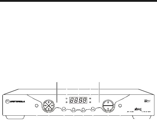
F r o n t P a n e l
Figure 2-1 illustrates the front panel, which contains selection keys, tuning keys, various displays, and the power switch:
F i g u r e 2 - 1
D C T 2 0 0 0 f r o n t p a n e l
1 |
2 |
3 |
4 |
5 |
|
CURSOR |
|
|
|
|
|
|
|
REMOTE |
|
CHANNEL |
|
|
|
|
|
|
|
||||
|
MESSAGES |
|
|
|
|
|
|
|
|
|
|
|||||||||||
|
|
|
|
|
|
|
|
|
|
|
|
|
|
|
|
|||||||
|
|
|
|
A/B |
|
|
POWER |
|
|
|
|
|
|
|
|
|
|
|
||||
|
|
|
|
|
|
|
|
|
|
|
|
|
|
|
|
|||||||
GUIDE |
|
|
|
INFO |
|
|
A/B |
|
|
|
POWER |
|
|
|
|
|
|
|
||||
|
|
|
|
|
|
MENU |
SELECT |
|
|
|
|
|
|
|
|
|
|
|
||||
|
|
|
|
|
|
|
|
|
|
|
|
|
|
|
|
|
|
|
|
|
|
|
|
|
|
|
|
|
|
|
|
|
|
|
|
|
|
|
|
|
|
|
|
|
|
|
|
|
|
|
|
|
|
|
|
|
|
|
|
|
|
|
|
|
|
|
|
|
6 |
7 |
8 |
9 |
10 |
11 |
12 |
13 |
These controls provide minimum, yet functional capability in the event the remote control is lost or temporarily out of service. Functions requiring a numeric entry are not available without a remote control.
D C T 2 0 0 0 I n s t a l l a t i o n M a n u a l

2 - 2 |
O v e r v i e w |
|
|
Table 2-1 describes the front-panel controls and LEDs:
T a b l e 2 - 1
F r o n t p a n e l
K e y F e a t u r e
1 |
A/B |
2 |
MESSAGES |
3


4 REMOTE
5 |
POWER |
6 |
GUIDE |
7 |
CURSOR |
|
INFO
8
MENU
9
SELEC T
10
11 |
A/B |
|
F u n c t i o n
Lights if optional switch is activated
Lights to indicate that a message is present
Normally displays current channel number or time of day; in the diagnostic mode, displays diagnostic codes
Flashes when an error-free signal is received from the remote control Lights when the unit is on
Displays the electronic program guide (EPG)
Moves the cursor in menu and program guide screens
Displays current channel and program information
Displays the Main menu
Selects function options and Pay-Per-View (PPV) events and tunes channels from the electronic program guide
When enabled, this switches an add-on module from one function to another function
CHANNEL
12
Changes channel up and down
13 |
POWER |
Turns DCT 2000 on/off
D C T 2 0 0 0 I n s t a l l a t i o n M a n u a l
O v e r v i e w |
2 - 3 |
|
|
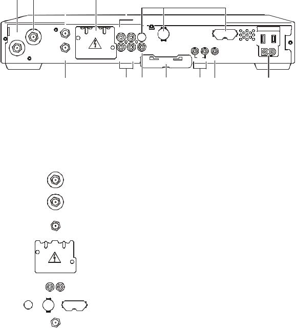
R e a r P a n e l
Figure 2-2 illustrates the rear panel of the DCT 2000 which contains a switched power outlet; connectors for video, audio, and RF cabling; data output connectors; and IR Blaster output connector:
F i g u r e 2 - 2
D C T 2 0 0 0 r e a r p a n e l
1 |
2 |
TO |
|
TV/VCR |
|
|
RF |
|
IN |
3 |
4 |
5 |
6 |
||||||||
|
|
|
|
|
|
|
|
|
|
|
|
|
|
|
|
|
|
|
|
|
|
|
|
|
|
|
|
|
|
|
|
|
|
|
|
|
|
|
|
|
|
|
|
|
|
|
|
|
|
|
|
|
|
|
|
|
|
|
|
|
|
|
|
|
|
|
|
|
|
|
|
AUX AUD IO IN SPDIF 

TO RF IN |
|
|
|
S-V IDEO |
|
|
|
|
|
|
|
|
HIGH |
OUT OF |
IR |
SWITCHED |
|
|
|
|
|
|
SPEED |
BAND |
|
105-125V |
|
|
|
|
|
|
|
|
|
|
|
|
|
|
|
|
|
60Hz |
CAB LE IN |
R |
L |
V IDEO |
T V Pass Card |
|
|
|
4A MAX |
AUD IO OU T |
|
|
|
|
|
500W MAX |
||
|
|
|
DATA |
|
||||
7 |
8 |
9 |
10 |
11 |
12 |
13 |
A protective plate covers the rear panel opening when the optional Telco return is not installed. Do not remove the protective plate unless you are installing new hardware in the opening.
Table 2-2 describes each of the rear-panel features:
T a b l e 2 - 2
R e a r p a n e l
Key
1
2
3
4
5
6
7
Item
TO
TV/VCR
R F
I N
TO R F IN
AUX AUDIO |
IN |
|
|
SPDIF
CAB LE IN
Function
F-type connector used to connect the DCT 2000 to a standard TV or VCR
F-type connector used for DCT 2000 input from the TO RF IN connector
F-type connector used to connect the TO RF IN port to the RF IN port (output from integrated RF return)
Covers slot used for STARFONE option
RCA jacks for looping through audio from auxiliary audio equipment
Options that enhance your DCT 2000; see, “Options” for more information
F-type connector used for the coaxial cable input port from plant (input to integrated RF return)
D C T 2 0 0 0 I n s t a l l a t i o n M a n u a l

2 - 4 |
O v e r v i e w |
|
|
Key |
Item |
|||
8 |
|
|
|
|
|
|
R |
L |
|
|
|
AUDIO OUT |
||
9 |
|
|
VIDEO |
|
|
|
|
|
|
10 |
|
T V Pass Card |
||
|
|
|
|
|
11 |
|
|
|
|
|
|
|
|
|
|
HIGH |
OUT OF |
||
|
SPEED |
BAND |
||
DATA
IR
12
13
Function
Left and right audio RCA jacks used for stereo audio output
RCA jack used to connect the DCT 2000 to a composite (baseband) video TV or a monitor; in some configurations this jack connects to a VCR
Cover for an area reserved for future use
Mini-phone jacks for connecting data output from the DCT 2000
Mini-phone jack for connecting an optional IR Blaster
AC power outlet that can be configured as a switched or unswitched outlet and the two-pronged plug is for attaching a power cord
O p t i o n s
The DCT 2000 supports a variety of options enabling your company to offer a system tailored to the individual needs of your subscribers. Figure 2-3 illustrates the options available for the DCT 2000:
F i g u r e 2 - 3
D C T 2 0 0 0 o p t i o n s
|
1 |
2 |
AUX AUD IO IN |
SPDIF |
|
TO |
|
|
T V/VCR |
|
|
TO RF IN |
|
S-V IDEO |
|
|
|
RF |
|
|
IN |
|
|
CAB LE IN |
R |
L |
V IDEO |
T V Pass Card |
|
|
|||
|
|
|
|
AUD IO OU T
3
HIGH |
OUT OF |
IR |
SWITCHED |
SPEED |
BAND |
|
105-125V |
|
|
|
|
|
|
|
60Hz |
|
|
|
4A MAX |
DATA |
|
500W MAX |
|
|
|
|
|
|
|
A |
|
|
|
|
|
|
|
|
|
|
|
|
|
|
|
|
|
|
|
|
|
|
|
|
|
|
A |
RF |
|
RF |
RF OUT |
||||||
|
|
|
|
|
|
|||||
|
|
|
|
|
|
|||||
|
|
|
|
|
|
|||||
|
IN |
|
|
|
|
|
||||
|
OUT |
|
|
|
|
|
|
|
|
|
CABLE IN |
|
|
|
CONV |
|
|
|
|
|
|
|
|
|
|
|
|
|
|
|||
|
|
|
|
IN |
|
|
|
PHONE |
||
B |
|
|
|
|
|
B |
||||
4 |
|
5 |
6 |
7 |
|
|||||
DCT 2000 Installation Manual

O v e r v i e w |
2 - 5 |
|
|
Table 2-3 describes the function of each of the options shown in Figure 2-3:
Table 2 - 3
Options
Key |
Option |
Name |
Function |
1 |
SPDIF |
|
SPDIF |
Used to deliver Dolby Digital 5.1, Dolby AC3 audio, or PCM audio |
|
(digital audio recording) |
2 |
S-VIDEO |
Used for high quality video to external devices such as high-end |
|
|
VCRs or TVs |
|
S-VI DEO |
|
3 |
PARALLEL PORT |
Interface this serial data connector to an external data device such |
|
|
as a printer |
4
5
6
A


CABLE IN
B


RF
RF IN
OUT
CONV
IN


 A
A

 RF OUT
B


A/B In |
Used in a dual cable system to receive both cables; verify the |
|
location of the A and B connectors on your particular A/B In |
|
module |
RF Bypass |
Enables the cable signal to bypass the DCT 2000 and go directly to |
|
a TV or VCR |
Dual A/B RF Bypass |
Used in a dual cable system; enables the cable signal on the |
|
current side (A or B) to go directly to a TV or VCR |
7 |
|
|
|
|
|
|
|
|
STARFONE |
Used in a two-way addressable system to send Impulse |
|
|
|
|
|
|
|
||||
|
|
|
|
|
|
|
|
|
|
Pay-Per-View (IPPV) information to the DAC 6000 or other |
|
|
|
|
|
|
|
|
|
|
|
|
|
|
|
|
|
|
|
|
|
|
|
|
|
|
|
|
|
controller through the subscriber’s telephone hookup |
|||
|
|
|
PHONE |
|
||||||
DCT 2000 Installation Manual

2 - 6 |
O v e r v i e w |
|
|
R e m o t e C o n t r o l s
The basic DCT 2000 uses the DRC 400 remote control. If your system offers optional interactive applications, such as an interactive program guide, a different remote control may be required. The application provider should supply user instructions for each interactive application.
DRC 400 Remote Control
Figure 2-4 illustrates the DRC 400:
Figure 2 - 4
DRC 400 remote control
|
|
1 |
|
|
|
|
VCR CABLE |
|
|||
|
AUX |
|
TV |
|
|
2 |
HELP |
|
|
|
|
|
POWER |
|
15 |
||
3 |
|
|
|||
|
|
|
|||
PAGE |
LOCK |
PAGE |
16 |
||
4 |
|||||
EXIT |
|
INFO |
|||
|
|
||||
5 |
|
|
|
17 |
|
6 |
|
OK |
|
|
|
7 |
|
|
|
||
|
|
MENU |
|
||
|
|
|
18 |
||
8 |
VOLUME |
LAST |
CHANNEL |
||
|
19 |
||||
|
|
|
|
||
9 |
|
FAVORITE |
|
20 |
|
|
|
|
|
||
10 |
A |
B |
C |
21 |
|
|
|
|
|
||
|
1 |
2 |
3 |
|
|
11 |
4 |
5 |
6 |
|
|
|
7 |
8 |
9 |
|
|
12 |
TV/VCR |
|
ENTER |
22 |
|
DAY |
0 |
DAY |
|||
|
|
|
|||
13 |
STOP |
PAUSE |
PLAY |
|
|
|
|
|
|
||
|
REW |
RECORD |
F.FWD |
|
|
|
|
|
|||
|
|
14 |
|
|
|
DCT 2000 Installation Manual

O v e r v i e w |
2 - 7 |
|
|
Table 2-4 describes the remote control keys:
Table 4
Remote control keys
Key |
Item |
D e s c r i p t i o n |
1 |
AUX, VCR, CABLE, or TV |
Selects a desired device to control. The selected mode will remain active until you press |
|
|
another key. |
2 |
HELP |
Displays the help screen. |
3 |
POWER |
Turns the selected home entertainment component on or off. |
4 |
PAGE ▲ or PAGE▼ |
Pages through menu screens and the program guide. |
5 |
EXIT |
Exits a menu or program guide. |
6 |
|
Moves the cursor around the program guide and menu screens. |
7 |
OK/SELECT |
Selects menu options, Pay-Per-View events or tune programs from the program guide. |
|
|
Your remote may only have OK; this key still performs the same functions. |
8 |
GUIDE |
Displays the program guide. |
9 |
VOLUME + or |
Increases or decreases the volume of the currently selected device. |
|
VOLUME - |
|
10 |
A, B , or C |
Functionality is determined from services offered by the service provider. |
11 |
NUMBER KEYS |
Directly selects a channel. |
12 |
TV/VCR |
Enables the RF bypass function. A cable-ready TV is required for this function to operate. |
|
BYPASS |
|
13 |
◄ Day |
Moves the program guide ahead or back 24 hours. |
|
Day ► |
|
14 |
STOP, PAUSE, PLAY, REW, |
Controls the VCR. |
|
RECORD, F.FWD |
|
15 |
MUTE |
Toggles the sound on and off. |
16 |
LOCK/PPV |
Limits viewing of selected programs; and is used to view the Pay-Per-View menu. Your |
|
|
remote may have only LOCK; this key still performs the same functions. |
17 |
INFO |
Displays the current channel and program information (not supported by all |
|
|
applications). |
18 |
MENU |
Displays the Main menu. |
19 |
LAST |
Recalls the last channel or goes back one screen in the menu. |
20 |
CHANNEL + or - |
Changes the channels by moving up or down. |
21 |
FAVORITE |
Displays preset favorite cable channels. |
22 |
ENTER/MUSIC |
Displays digital music channel menus. On some TV models, press to enter channels. |
DCT 2000 Installation Manual

2 - 8 |
O v e r v i e w |
|
|
Installing Batteries in Remote Control
Before using the remote control, you must install two AA (1.5 V) alkaline batteries. Figure 2-5 illustrates battery access on the back of the remote control.
To install batteries in an DRC 400:
1Press and slide the battery compartment cover off.
2Place the batteries in the compartment; be careful to observe the correct polarity.
3Slide the battery compartment cover back into place.
Battery installation will vary with each style of remote control. Refer to the user instructions included with your remote control for installing batteries.
Figure 2 - 5
Back view of remote control
+ 

+
DCT 2000 Installation Manual

Section 3
I n s t a l l a t i o n
This section provides instructions for installing and cabling the DCT 2000. To complete the installation, you must:
§Connect the cables
§Supply power to equipment
§Download configuration information and software
§Run operational check and diagnostics
B e f o r e Y o u B e g i n
Before you begin, review the installation instructions, gather the required items, and complete the tasks listed below:
§Determine if the subscriber’s system requirements include an A/B In, RF Bypass, Dual A/B-RF Bypass module, or a STARFONE module. These options can be installed before leaving the office. Installation instructions are provided with these modules.
§Verify that you have 75-ohm coaxial cables with F-type connectors and RCA baseband phonotype cables.
§Determine if you are connecting the DCT 2000 to a standard TV or a composite (baseband) monitor.
§Place the DCT 2000 on a smooth, flat surface and remove any obstructions that could interfere with the free flow of air over, under, or around it. Advise the subscriber not to place anything on top of the unit.
I n s t a l l i n g t h e D C T 2 0 0 0
To install the DCT 2000:
1If an add-on module is required and it was not previously installed, do that now. When installed, verify that the appropriate configuration information has been downloaded via the access control system.
2Determine if you are connecting the DCT 2000 to a conventional TV or to a monitor. To install the video connection:
§For a conventional TV, use a 75-ohm coaxial cable with F-type connectors.
§For a monitor, use an RCA phono cable to connect the VIDEO connector to the monitor.
3Locate the cabling diagram that matches the subscriber’s configuration requirement.
4Connect the cables as illustrated in the diagram.
5Perform the basic operational check in this section after the DCT 2000 is installed.
DCT 2000 Installation Manual
3 - 2 |
I n s t a l l a t i o n |
|
|
S t a n d a r d C a b l i n g D i a g r a m
The DCT 2000 will output on either channel 3 or 4 depending on the configuration message from the control system. Figure 3-1 illustrates a standard diagram connecting the DCT 2000 to a TV using RF connectors:
Figure 3 - 1
Standard cabling
|
|
|
|
|
|
|
|
|
|
|
|
|
|
|
|
|
|
|
|
|
|
|
|
|
|
|
|
|
|
|
|
|
|
|
|
|
|
|
|
|
|
|
|
|
|
|
|
|
|
|
|
|
|
|
|
|
|
|
|
|
|
|
|
|
|
|
|
|
|
|
|
|
|
|
|
|
|
|
|
|
|
|
|
|
|
|
|
|
|
|
|
|
|
|
|
|
AUX AUDIO IN |
SPDIF |
|
|
|
|
|
|
|
|
|
||||
|
|
|
|
|
|
|
|
|
|
|
|
|
|
|
|
|
|
|
|
|
|
|
|
|
|
|
|
TO |
|
|
|
|
|
|
|
|
TV/VCR |
|
|
|
|
|
|
|
|
TO RF IN |
|
|
|
S-V IDEO |
|
|
|
SWITCHED |
|
|
|
|
HIGH |
OUT OF |
IR |
||
RF |
|
|
|
|
SPEED |
BAND |
|
105-125V |
|
|
|
|
|
|
|
||
IN |
|
|
|
|
|
|
|
60Hz |
|
|
|
VIDEO |
|
|
|
|
|
CAB LE IN |
R |
L |
T V Pass Card |
|
|
|
4A MAX |
|
AUDIO OU T |
|
|
|
|
|
500W MAX |
||
|
|
|
DATA |
|
||||
 From cable outlet
AUDIO
IN
|
R |
L |
|
|
AUDIO |
|
SVIDEO |
CABLE IN |
OUT |
VIDEO |
|
|
|
IN |
IN |
|
R |
L |
|
TV
The remodulated channel, 3 or 4, does not carry stereo for digital channels. Connect the DCT 2000 using RCA baseband connectors to receive stereo on digital channels. These connections are illustrated later in this section.
DCT 2000 Installation Manual
Loading...