


DS9208-1D

DS9208-1D
DIGITAL SCANNER
PRODUCT REFERENCE
GUIDE


DS9208-1D
PRODUCT REFERENCE GUIDE
72E-162626-01
Revision A
May 2012

ii DS9208-1D Product Reference Guide
© 2012 Motorola Solutions, Inc. All rights reserved.
No part of this publication may be reproduced or used in any form, or by any electrical or mechanical means,
without permission in writing from Motorola. This includes electronic or mechanical means, such as
photocopying, recording, or information storage and retrieval systems. The material in this manual is subject to
change without notice.
The software is provided strictly on an “as i s” basis. All sof twar e, including firmware, furnished to the user is on
a licensed basis. Motorola grants to the user a non-transferab le and non-exclusive license to use each
software or firmware program delivered hereunder (licensed program). Except as noted below, such license
may not be assigned, sublicensed, or otherwise transferred by the user without prior written consent of
Motorola. No right to copy a licensed program in whole or in part is granted, except as permitted unde r
copyright law. The user shall not modify, merge, or incorporate any form or portion of a licensed program with
other program material, create a derivative work from a licensed program, or use a licensed program in a
network without written permission from Motorola. The user agrees to maintain Motorola’s copyright notice on
the licensed programs delivered hereunder, and to include the same on any authorized copies it makes, in
whole or in part. The user agrees not to deco mpile, disassemble, decode, or reverse engineer any licensed
program delivered to the user or any portion thereof.
Motorola reserves the right to make changes to any software or product to improve reliability, function, or
design.
Motorola does not assume any product liability arising out of, or in connection with, the application or use of
any product, circuit, or application described herein.
No license is granted, either expressly or by implication, estoppel, or otherwise under any Motorola, Inc.,
intellectual property rights. An implied license only exists for equipment, circuits, and subsystems contained in
Motorola products.
MOTOROLA, MOTO, MOTOROLA SOLUTIONS and the Stylized M Logo are trademarks or registered
trademarks of Motorola Trademark Holdings, LLC and are used under license. All other trademarks are the
property of their respective owners.
Motorola Solutions, Inc.
One Motorola Plaza
Holtsville, New York 11742-1300
http://www.motorolasolutions.com
Warranty
For the complete Motorola hardware product warranty statement, go to:
http://www.motorola.com/enterprisemobility/warranty.

iii
Revision History
Changes to the original guide are listed below:
Change Date Description
-01 Rev A 5/2012 Initial release

iv DS9208-1D Product Reference Guide

TABLE OF CONTENTS
About This Guide
Introduction..................................................................................................................................... xiii
Configurations................................................................................................................................. xiii
Chapter Descriptions...................................................................................................................... xiv
Notational Conventions................................................................................................................... xv
Related Documents........................................................................................................................ xv
Service Information......................................................................................................................... xvi
Chapter 1: Getting Started
Introduction .................................................................................................................................... 1-1
Interfaces ....................................................................................................................................... 1-2
Unpacking ...................................................................................................................................... 1-2
Setting Up the Digital Scanner ....................................................................................................... 1-3
Installing the Interface Cable ................................................................................................... 1-3
Connecting Power (if required) ................................................................................................ 1-3
Configuring the Digital Scanner ............................................................................................... 1-4
Mounting the Digital Scanner ......................................................................................................... 1-4
Wall Mount Bracket .................................................................................................................. 1-4
Locking Mount Bracket ............................................................................................................ 1-5
Accessories ................................................................................................................................... 1-7
Required Accessories .............................................................................................................. 1-7
Optional Accessories ............................................................................................................... 1-7
Electronic Article Surveillance (EAS) (Optional) ............................................................................ 1-7
Mounting Templates ...................................................................................................................... 1-8
Chapter 2: Data Capture
Introduction .................................................................................................................................... 2-1
Beeper Definitions ......................................................................................................................... 2-2
Selecting Beeper Volume using Trigger .................................................................................. 2-4
LED Definitions .............................................................................................................................. 2-4
Scanning ........................................................................................................................................ 2-5
Presentation Mode Scanning ................................................................................................... 2-5
Momentary Trigger Mode Scanning ......................................................................................... 2-6
Decode Ranges ............................................................................................................................. 2-8

vi DS9208-1D Product Reference Guide
Integrated Electronic Article Surveillance (EAS) ............................................................................ 2-8
Deactivation Antenna for Checkpoint EAS Systems ................................................................ 2-8
EAS Deactivation Range ......................................................................................................... 2-8
DS9208 Host Interface Cables and EAS ................................................................................. 2-8
Checkpoint Contact Information ............................................................................................... 2-8
Chapter 3: Maintenance & Technical Specifications
Introduction .................................................................................................................................... 3-1
Maintenance .................................................................................................................................. 3-1
Troubleshooting ............................................................................................................................. 3-2
Report Software Version Bar Code .......................................................................................... 3-4
Technical Specifications ................................................................................................................ 3-5
Digital Scanner Signal Descriptions ............................................................................................... 3-7
Chapter 4: User Preferences & Miscellaneous Options
Introduction .................................................................................................................................... 4-1
Scanning Sequence Examples ...................................................................................................... 4-2
Errors While Scanning ................................................................................................................... 4-2
User Preferences/Miscellaneous Options Parameter Defaults ...................................................... 4-2
User Preferences ........................................................................................................................... 4-4
Set Default Parameter ............................................................................................................. 4-4
Parameter Bar Code Scanning ................................................................................................ 4-5
Beep After Good Decode ......................................................................................................... 4-5
Beeper Tone ............................................................................................................................ 4-6
Beeper Volume ........................................................................................................................ 4-7
Volume Adjustment Trigger Timeout ....................................................................................... 4-8
Beeper Duration ....................................................................................................................... 4-9
Suppress Power-up Beeps ...................................................................................................... 4-9
Low Power Mode ..................................................................................................................... 4-10
Time Delay to Low Power Mode .............................................................................................. 4-11
Trigger Mode ............................................................................................................................ 4-13
Trigger Aiming Pattern ............................................................................................................. 4-14
Presentation Aiming Pattern .................................................................................................... 4-15
Momentary Trigger Mode Timeout ........................................................................................... 4-16
Motion Detect Range ............................................................................................................... 4-17
Decoding Illumination (Hand-Held Mode Only) ........................................................................ 4-18
Post Decode Illumination ......................................................................................................... 4-18
Illumination Always On (Presentation Mode Only) ................................................................... 4-19
Presentation Mode Field of View ............................................................................................. 4-20
Picklist Mode ............................................................................................................................ 4-21
Continuous Bar Code Read ..................................................................................................... 4-22
Unique Bar Code Reporting ..................................................................................................... 4-22
Decode Session Timeout ......................................................................................................... 4-23
Timeout Between Decodes, Same Symbol ............................................................................. 4-23
Timeout Between Decodes, Different Symbols ....................................................................... 4-24
Fuzzy 1D Processing ............................................................................................................... 4-24
Motion Tolerance (Hand-Held Trigger Modes Only) ................................................................ 4-25
Miscellaneous Scanner Parameters .............................................................................................. 4-26
Transmit Code ID Character .................................................................................................... 4-26
Prefix/Suffix Values .................................................................................................................. 4-27

Table of Contents vii
Scan Data Transmission Format ............................................................................................. 4-28
FN1 Substitution Values .......................................................................................................... 4-29
Transmit “No Read” Message .................................................................................................. 4-30
Chapter 5: USB Interface
Introduction .................................................................................................................................... 5-1
Connecting a USB Interface .......................................................................................................... 5-2
USB Parameter Defaults ................................................................................................................ 5-3
USB Host Parameters .................................................................................................................... 5-4
USB Device Type ..................................................................................................................... 5-4
Symbol Native API (SNAPI) Status Handshaking .................................................................... 5-5
USB Country Keyboard Types - Country Codes ...................................................................... 5-6
USB Keystroke Delay .............................................................................................................. 5-8
Simulated Caps Lock ............................................................................................................... 5-9
USB CAPS Lock Override ....................................................................................................... 5-9
USB Ignore Unknown Characters ............................................................................................ 5-10
USB Convert Unknown to Code 39 ......................................................................................... 5-10
USB Ignore Beep Directive ...................................................................................................... 5-11
USB Ignore Type Directive ...................................................................................................... 5-11
Emulate Keypad ....................................................................................................................... 5-12
Emulate Keypad with Leading Zero ......................................................................................... 5-12
USB Keyboard FN 1 Substitution ............................................................................................. 5-13
Function Key Mapping ............................................................................................................. 5-13
Convert Case ........................................................................................................................... 5-14
USB Static CDC ....................................................................................................................... 5-14
USB Transmission Speed Parameters .................................................................................... 5-15
IBM Specification Version ........................................................................................................ 5-18
ASCII Character Set for USB ......................................................................................................... 5-19
Chapter 6: RS-232 Interface
Introduction .................................................................................................................................... 6-1
Connecting an RS-232 Interface .................................................................................................... 6-2
RS-232 Parameter Defaults ........................................................................................................... 6-3
RS-232 Host Parameters ............................................................................................................... 6-4
RS-232 Host Types .................................................................................................................. 6-6
Baud Rate ................................................................................................................................ 6-8
Parity ........................................................................................................................................ 6-9
Stop Bits ................................................................................................................................... 6-10
Data Bits .................................................................................................................................. 6-10
Check Receive Errors .............................................................................................................. 6-11
Hardware Handshaking ........................................................................................................... 6-11
Software Handshaking ............................................................................................................. 6-13
Host Serial Response Timeout ................................................................................................ 6-15
RTS Line State ......................................................................................................................... 6-16
Beep on <BEL> ........................................................................................................................ 6-16
Intercharacter Delay ................................................................................................................. 6-17
Nixdorf Beep/LED Options ....................................................................................................... 6-18
Ignore Unknown Characters .................................................................................................... 6-18
ASCII Character Set for RS-232 .................................................................................................... 6-19

viii DS9208-1D Product Reference Guide
Chapter 7: IBM 468X / 469X Interface
Introduction .................................................................................................................................... 7-1
Connecting to an IBM 468X/469X Host ......................................................................................... 7-2
IBM Parameter Defaults ................................................................................................................ 7-3
IBM 468X/469X Host Parameters .................................................................................................. 7-4
Port Address ............................................................................................................................ 7-4
Convert Unknown to Code 39 .................................................................................................. 7-5
Ignore Beep Directive .............................................................................................................. 7-5
Ignore Configuration Directive ................................................................................................. 7-6
Chapter 8: Keyboard Wedge Interface
Introduction .................................................................................................................................... 8-1
Connecting a Keyboard Wedge Interface ...................................................................................... 8-2
Keyboard Wedge Parameter Defaults ........................................................................................... 8-3
Keyboard Wedge Host Parameters ............................................................................................... 8-4
Keyboard Wedge Host Types .................................................................................................. 8-4
Keyboard Wedge Country Types - Country Codes .................................................................. 8-5
Ignore Unknown Characters .................................................................................................... 8-7
Keystroke Delay ....................................................................................................................... 8-7
Intra-Keystroke Delay .............................................................................................................. 8-8
Alternate Numeric Keypad Emulation ...................................................................................... 8-8
Simulated Caps Lock ............................................................................................................... 8-9
Caps Lock Override ................................................................................................................. 8-9
Convert Wedge Data ............................................................................................................... 8-10
Function Key Mapping ............................................................................................................. 8-10
FN1 Substitution ...................................................................................................................... 8-11
Send Make and Break ............................................................................................................. 8-11
Keyboard Maps ........................................................................................................................ 8-12
ASCII Character Set for Keyboard Wedge .................................................................................... 8-13
Chapter 9: Symbologies
Introduction .................................................................................................................................... 9-1
Scanning Sequence Examples ...................................................................................................... 9-1
Errors While Scanning ................................................................................................................... 9-2
Symbology Parameter Defaults ..................................................................................................... 9-2
Disable All Code Types ................................................................................................................. 9-6
UPC/EAN ....................................................................................................................................... 9-7
Enable/Disable UPC-A ............................................................................................................. 9-7
Enable/Disable UPC-E ............................................................................................................. 9-7
Enable/Disable UPC-E1 ........................................................................................................... 9-8
Enable/Disable EAN-8/JAN-8 .................................................................................................. 9-8
Enable/Disable EAN-13/JAN-13 .............................................................................................. 9-9
Enable/Disable Bookland EAN ................................................................................................ 9-9
Bookland ISBN Format ............................................................................................................ 9-10
Decode UPC/EAN/JAN Supplementals ................................................................................... 9-11
User-Programmable Supplementals ........................................................................................ 9-14
UPC/EAN/JAN Supplemental Redundancy ............................................................................. 9-14
UPC/EAN/JAN Supplemental AIM ID Format .......................................................................... 9-15
Transmit UPC-A Check Digit ................................................................................................... 9-16
Transmit UPC-E Check Digit ................................................................................................... 9-16

Table of Contents ix
Transmit UPC-E1 Check Digit ................................................................................................. 9-17
UPC-A Preamble ..................................................................................................................... 9-17
UPC-E Preamble ..................................................................................................................... 9-18
UPC-E1 Preamble ................................................................................................................... 9-19
Convert UPC-E to UPC-A ........................................................................................................ 9-20
Convert UPC-E1 to UPC-A ...................................................................................................... 9-20
EAN-8/JAN-8 Extend ............................................................................................................... 9-21
UCC Coupon Extended Code .................................................................................................. 9-21
Coupon Report ......................................................................................................................... 9-22
ISSN EAN ................................................................................................................................ 9-23
Code 128 ....................................................................................................................................... 9-24
Enable/Disable Code 128 ........................................................................................................ 9-24
Set Lengths for Code 128 ........................................................................................................ 9-24
Enable/Disable GS1-128 (formerly UCC/EAN-128) ................................................................. 9-25
Enable/Disable ISBT 128 ......................................................................................................... 9-26
ISBT Concatenation ................................................................................................................. 9-27
Check ISBT Table .................................................................................................................... 9-28
ISBT Concatenation Redundancy ............................................................................................ 9-28
Code 39 ......................................................................................................................................... 9-29
Enable/Disable Code 39 .......................................................................................................... 9-29
Enable/Disable Trioptic Code 39 ............................................................................................. 9-29
Convert Code 39 to Code 32 ................................................................................................... 9-30
Code 32 Prefix ......................................................................................................................... 9-30
Set Lengths for Code 39 .......................................................................................................... 9-31
Code 39 Check Digit Verification ............................................................................................. 9-32
Transmit Code 39 Check Digit ................................................................................................. 9-32
Code 39 Full ASCII Conversion ............................................................................................... 9-33
Code 39 Buffering .................................................................................................................... 9-34
Code 93 ......................................................................................................................................... 9-36
Enable/Disable Code 93 .......................................................................................................... 9-36
Set Lengths for Code 93 .......................................................................................................... 9-36
Code 11 ......................................................................................................................................... 9-38
Code 11 ................................................................................................................................... 9-38
Set Lengths for Code 11 .......................................................................................................... 9-38
Code 11 Check Digit Verification ............................................................................................. 9-40
Transmit Code 11 Check Digits ............................................................................................... 9-41
Interleaved 2 of 5 (ITF) .................................................................................................................. 9-41
Enable/Disable Interleaved 2 of 5 ............................................................................................ 9-41
Set Lengths for Interleaved 2 of 5 ............................................................................................ 9-41
I 2 of 5 Check Digit Verification ................................................................................................ 9-44
Transmit I 2 of 5 Check Digit .................................................................................................... 9-44
Convert I 2 of 5 to EAN-13 ....................................................................................................... 9-45
Discrete 2 of 5 (DTF) ..................................................................................................................... 9-45
Enable/Disable Discrete 2 of 5 ................................................................................................. 9-45
Set Lengths for Discrete 2 of 5 ................................................................................................ 9-46
Codabar (NW - 7) ........................................................................................................................... 9-48
Enable/Disable Codabar .......................................................................................................... 9-48
Set Lengths for Codabar .......................................................................................................... 9-48
CLSI Editing ............................................................................................................................. 9-50
NOTIS Editing .......................................................................................................................... 9-50
Codabar Upper or Lower Case Start/Stop Characters Detection ............................................ 9-51

x DS9208-1D Product Reference Guide
MSI ................................................................................................................................................ 9-52
Enable/Disable MSI ................................................................................................................. 9-52
Set Lengths for MSI ................................................................................................................. 9-52
MSI Check Digits ..................................................................................................................... 9-54
Transmit MSI Check Digit(s) .................................................................................................... 9-54
MSI Check Digit Algorithm ....................................................................................................... 9-55
Chinese 2 of 5 ................................................................................................................................ 9-55
Enable/Disable Chinese 2 of 5 ................................................................................................. 9-55
Matrix 2 of 5 ................................................................................................................................... 9-56
Enable/Disable Matrix 2 of 5 .................................................................................................... 9-56
Set Lengths for Matrix 2 of 5 .................................................................................................... 9-57
Matrix 2 of 5 Check Digit .......................................................................................................... 9-58
Transmit Matrix 2 of 5 Check Digit ........................................................................................... 9-58
Korean 3 of 5 ................................................................................................................................. 9-59
Enable/Disable Korean 3 of 5 .................................................................................................. 9-59
Inverse 1D ..................................................................................................................................... 9-60
GS1 DataBar ................................................................................................................................. 9-61
GS1 DataBar ............................................................................................................................ 9-61
GS1 DataBar Limited ............................................................................................................... 9-62
GS1 DataBar Limited Security Level ....................................................................................... 9-63
GS1 DataBar Expanded .......................................................................................................... 9-64
Convert GS1 DataBar to UPC/EAN ......................................................................................... 9-64
Redundancy Level ......................................................................................................................... 9-65
Redundancy Level 1 ................................................................................................................ 9-65
Redundancy Level 2 ................................................................................................................ 9-65
Redundancy Level 3 ................................................................................................................ 9-65
Redundancy Level 4 ................................................................................................................ 9-66
Security Level ................................................................................................................................ 9-67
Intercharacter Gap Size ........................................................................................................... 9-68
Chapter 10: 123Scan2
Introduction .................................................................................................................................... 10-1
Communication with 123Scan2 ..................................................................................................... 10-1
123Scan2 Requirements ............................................................................................................... 10-2
Scanner SDK, Other Software Tools, and Videos ......................................................................... 10-2
Chapter 11: Advanced Data Formatting
Introduction .................................................................................................................................... 11-1
Appendix A: Standard Default Parameters
Appendix B: Programming Reference
Symbol Code Identifiers ................................................................................................................. B-1
AIM Code Identifiers ...................................................................................................................... B-2

Table of Contents xi
Appendix C: Sample Bar Codes
Code 39 ......................................................................................................................................... C-1
UPC/EAN ....................................................................................................................................... C-1
UPC-A, 100% ........................................................................................................................... C-1
EAN-13, 100% ......................................................................................................................... C-2
Code 128 ....................................................................................................................................... C-2
Interleaved 2 of 5 ........................................................................................................................... C-2
GS1 DataBar-14 ............................................................................................................................ C-3
Appendix D: Numeric Bar Codes
Numeric Bar Codes ........................................................................................................................ D-1
Cancel ............................................................................................................................................ D-2
Appendix E: ASCII Character Sets
Index

xii DS9208-1D Product Reference Guide

ABOUT THIS GUIDE
Introduction
The DS9208-1D Product Reference Guide provides general instructions for setting up, operating, maintain ing, and
troubleshooting the DS9208-1D digital scanner.
Configurations
This guide includes the following DS9208-1D digital scanner configurations:
•
DS9208-1D00004NNWW - DS9208-1D Digital Scanner, Standard Range, Black
•
DS9208-1D00004CNWW - DS9208-1D Digital Scanner, Standard Range, Black, Checkpoint EAS
•
DS9208-1D0000WNNWW - DS9208-1D Digital Scanner, Standard Range, White
•
DS9208-1D0000WCNWW - DS9208-1D Digital Scanner, Standard Range, White, Checkpoint EAS

xiv DS9208-1D Product Reference Guide
Chapter Descriptions
Topics covered in this guide are as follows:
•
Chapter 1, Getting Started provides a product overview, unpacking instructions, cable connection, and
mounting information.
•
Chapter 2, Data Capture describes parts of the digital scanner, beeper and LED definitions, and how to
use the scanner in hand-held and hands-free (presentation) modes.
•
Chapter 3, Maintenance & Technical Specifications provides information on how to care for the digital
scanner, troubleshooting, and technical specifications.
•
Chapter 4, User Preferences & Miscellaneous Options describes features frequently used to customiz e
how data transmits to the host device and programming bar codes for selecting user preference features
for the digital scanner.
•
Chapter 5, USB Interface describes how to set up the digital scanner with a USB host.
•
Chapter 6, RS-232 Interface describes how to set up the digital scanner with an RS-232 host, such as
point-of-sale devices, host computers, or other devices with an available RS-232 port.
•
Chapter 7, IBM 468X / 469X Interface describes how to set up the digital scanner with IBM 468X/469X
POS systems.
•
Chapter 8, Keyboard Wedge Interface describes how to set up a Keyboard Wedge interface with the
digital scanner.
•
Chapter 9, Symbologies describes all symbology features and provides programming bar codes for
selecting these features for the digital scanner.
•
Chapter 10, 123Scan2 describeds this PC-based scanner configuration tool which enables rapid and
easy customized setup of Symbol scanners.
•
Chapter 11, Advanced Data Formatting briefly describes ADF, a means of customizing data before
transmission to the host device, and includes a reference to the ADF Programmer Guide.
•
Appendix A, Standard Defaul t Parameters provides a table of all host devices and miscellaneous
scanner defaults.
•
Appendix B, Programming Reference provides a table of AIM code identifiers, ASCII character
conversions, and keyboard maps.
•
Appendix C, Sample Bar Codes includes sample bar codes of various code types.
•
Appendix D, Numeric Bar Codes includes the numeric bar codes to scan for parameters requiring
specific numeric values.
•
Appendix E, ASCII Character Sets provides ASCII character value tables.

About This Guide xv
Notational Conventions
The following conventions are used in this document:
•
Italics are used to highlight the following:
• Chapters and sections in this and related documents
• Dialog box, window and screen names
• Drop-down list and list box names
• Check box and radio button names
•
Bold text is used to highlight the following:
• Key names on a keypad
• Button names on a screen.
•
bullets (•) indicate:
• Action items
• Lists of alternatives
• Lists of required steps that are not necessarily sequential
•
Sequential lists (e.g., those that describe step-by-step procedures) appear as numbered lists.
•
Throughout the programming bar code menus, asterisks (*) are used to denote default parameter
settings.
Related Documents
•
DS9208 Quick Start Guide, p/n 72-140088-xx - provides gene ral information for getting started with the
DS9208 digital scanner, and includes basic set up and operation instructions.
•
Advanced Data Formatting Programmer Guide, p/n 72E-6 9680-xx - provides information on ADF, a
means of customizing data before transmission to a host.
For the latest version of this guide and all Motorola guides, go to: http://www.motorolasolutions.com/support.
*Baud Rate 9600
Feature/Option
* Indicates Default

xvi DS9208-1D Product Reference Guide
Service Information
If you have a problem using the equipment, contact your facility's technical or systems support. If there is a
problem with the equipment, they will contact the Motorola Solutions Global Customer Support Center at:
http://www.motorolasolutions.com/support.
When contacting Motorola Solutions support, please have the following informa tion available:
•
Serial number of the unit
•
Model number or product name
•
Software type and version number
Motorola responds to calls by e-mail, telephone or fax within the time limits set forth in service agreements.
If your problem cannot be solved by Motorola Solutions support, you may need to return your equipment for
servicing and will be given specific directions. Motorola is not responsible for any damages incurred during
shipment if the approved shipping container is not used. Shipping the units improperly can possibly void the
warranty.
If you purchased your business product from a Motorola business partner, please contact that business partner
for support.

CHAPTER 1 GETTING STARTED
Introduction
The DS9208-1D combines superior 1D omnidirectional bar code scanning and adva nced feature set in a
compact design. The digital scanner’s built-in stand seamlessly accommodates both counter-top and
hand-held use. Whether in presentation or trigger mode, the digital scanner ensures comfort and ease of use
for extended periods of time.
Figure 1-1
DS9208-1D Digital Scanner

1 - 2 DS9208-1D Product Reference Guide
Interfaces
The DS9208-1D digital scanner supports:
•
USB connection to a host. The digital scanner autodetects a USB host and defaults to the HID keyboard
interface type. Select other USB interface types by scanning programming bar code menus.This
interface supports the following international keyboards (for Windows® environment): North America,
German, French, French Canadian, Spanish, Italian, Swedish, UK English, Portuguese-Brazilian, and
Japanese.
•
Standard RS-232 connection to a host. Scan bar code menus to set up communication of the digital
scanner with the host.
•
RS-485 connection to IBM 468X/469X hosts. Scan bar code menus to set up communication of the
digital scanner with the IBM terminal.
•
Keyboard Wedge connection to a host. The host interprets scanned data as keystrokes. Scan bar code
menus to set up communication of the digital scanner with the host. This interface supports the following
international keyboards (for Windows® environment): North America, German, French, French
Canadian, French Belgian, Spanish, Italian, Swedish, UK English, Portuguese-Brazilian, and Japanese.
Unpacking
Remove the digital scanner from its packing and inspect it for damage. If the scanner was damaged in transit,
contact Motorola Solutions Global Customer Support Center. See page xvi for contact information. KEEP THE
PACKING. It is the approved shipping container; use this to return the equipment for servicing.
Getting Started 1 - 3
Setting Up the Digital Scanner
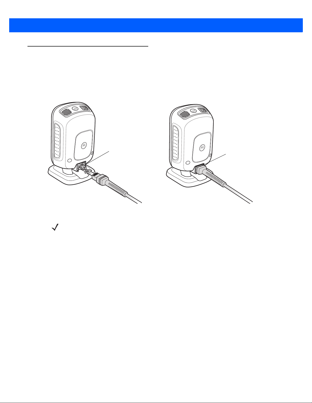
Installing the Interface Cable
1. Insert the interface cable modular connector into the interface cable port on the rear of the digital scanner
until you hear a click. The green LED lights and low/medium/high beeps sound, indicating that the scanner
is operational.
Figure 1-2
Installing the Cable
2. Gently tug the cable to ensure the connector is secure.
3. Connect the other end of the interface cable to the host (see the specific host chapter for information on
host connections).
Removing the Interface Cable
1. Tilt the scanner fully forward.
2. Using the tip of a small screwdriver, depress the cable’s modular connector clip and carefully slide out the
cable.
Connecting Power (if required)
If the host does not provide power to the digital scanner, connect an external power supply.
1. Plug the power supply into the power jack on the interface cable.
2. Plug the other end of the power supply into an AC outlet.
Interface cable
modular connector
To host
Cable interface port
NOTE Different hosts require different cables. The connectors illustrated in each host chapter are examples only.
Connectors vary from those illustrated, but the steps to connect the digital scanner are the same.
1 - 4 DS9208-1D Product Reference Guide
Configuring the Digital Scanner
To configure the digital scanner use the bar codes included in this manual, or use the 123Scan
2
configuration
program. See Chapter 4, User Preferences & Miscellaneous Options and Chapter 9, Sym bologies for
information about programming the digital scanner using bar code men us. See Chapter 10, 123Scan2 for
information on using this configuration program. Also see each host-specific chapter to set up connection to a
specific host type.
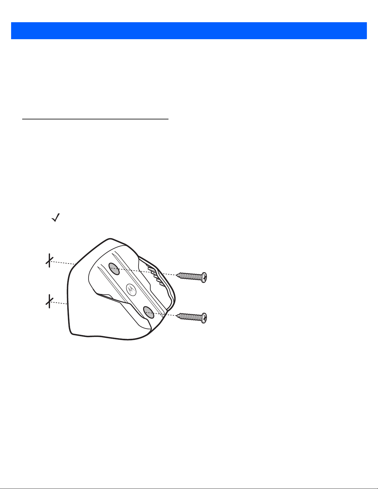
Mounting the Digital Scanner
Wall Mount Bracket
An optional wall mount bracket is available for mounting the scanner to a wall or other vertical surface. For a
template that facilitates screw placement, see Mounting Templates on page 1-8.
To mount the DS9208-1D:
1. Place the bracket in its desired location on the wall, and insert two #8 screws through each screw hole in
the bracket.
Figure 1-3
Installing the Wall Mount Bracket
2. Tighten the screws to secure the bracket to the wall.
NOTE Select a screw type and length appropriate for the wall material.
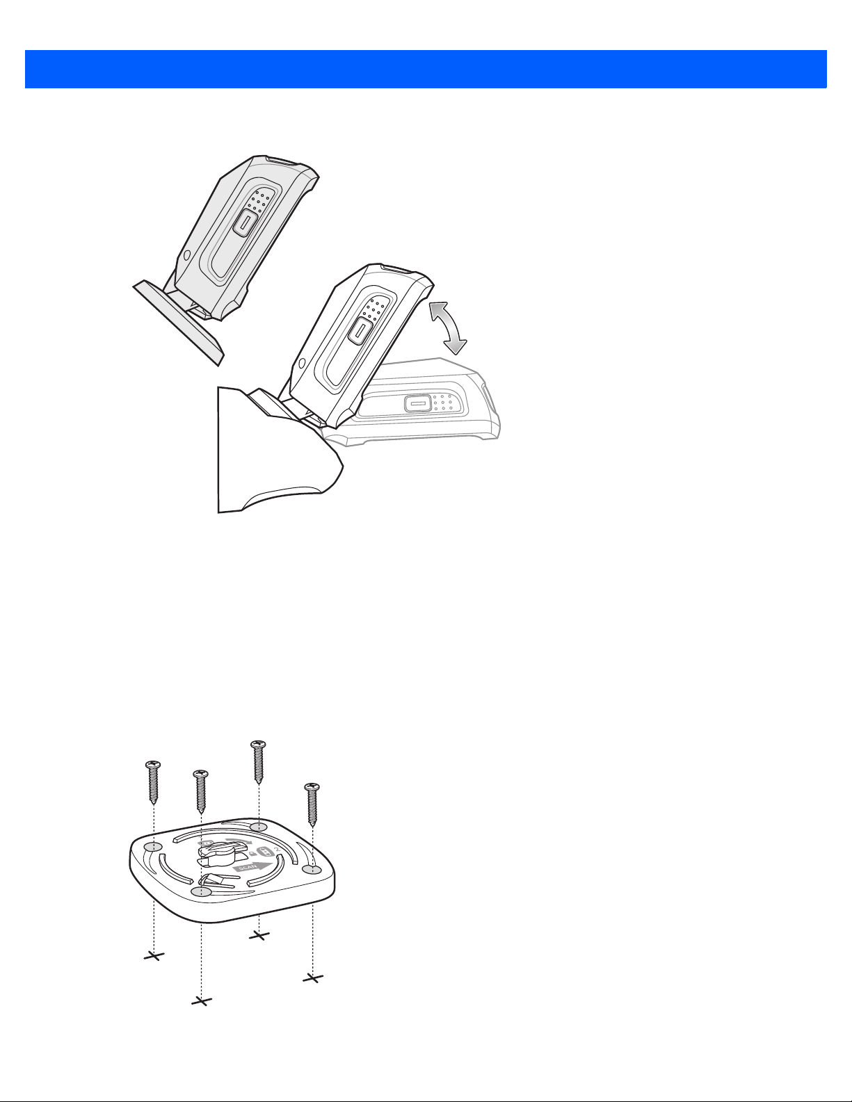
Getting Started 1 - 5
3. Slide the base of the digital scanner into the bracket, oriented so the scan window faces down.
Figure 1-4
Inserting the DS9208-1D into the Wall Mount Bracket
Locking Mount Bracket
An optional locking mount bracket is available for "locking" the scanner into position on a horizontal (or vertical)
surface. This option is recommended for applications where it is desirable to affix the scanner to a counter or
desktop. For a template that facilitates screw placement, see Mounting Templates on page 1-8.
To mount the DS9208-1D:
1. Place the bracket in its desired location on the counter or desktop. Make sure that the indicator on the
bracket is consistent with the direction that the scanner will face. Insert four #8 screws through each screw
hole in the bracket.
Figure 1-5
Figure 1-4 Installing the Locking Mount Bracket
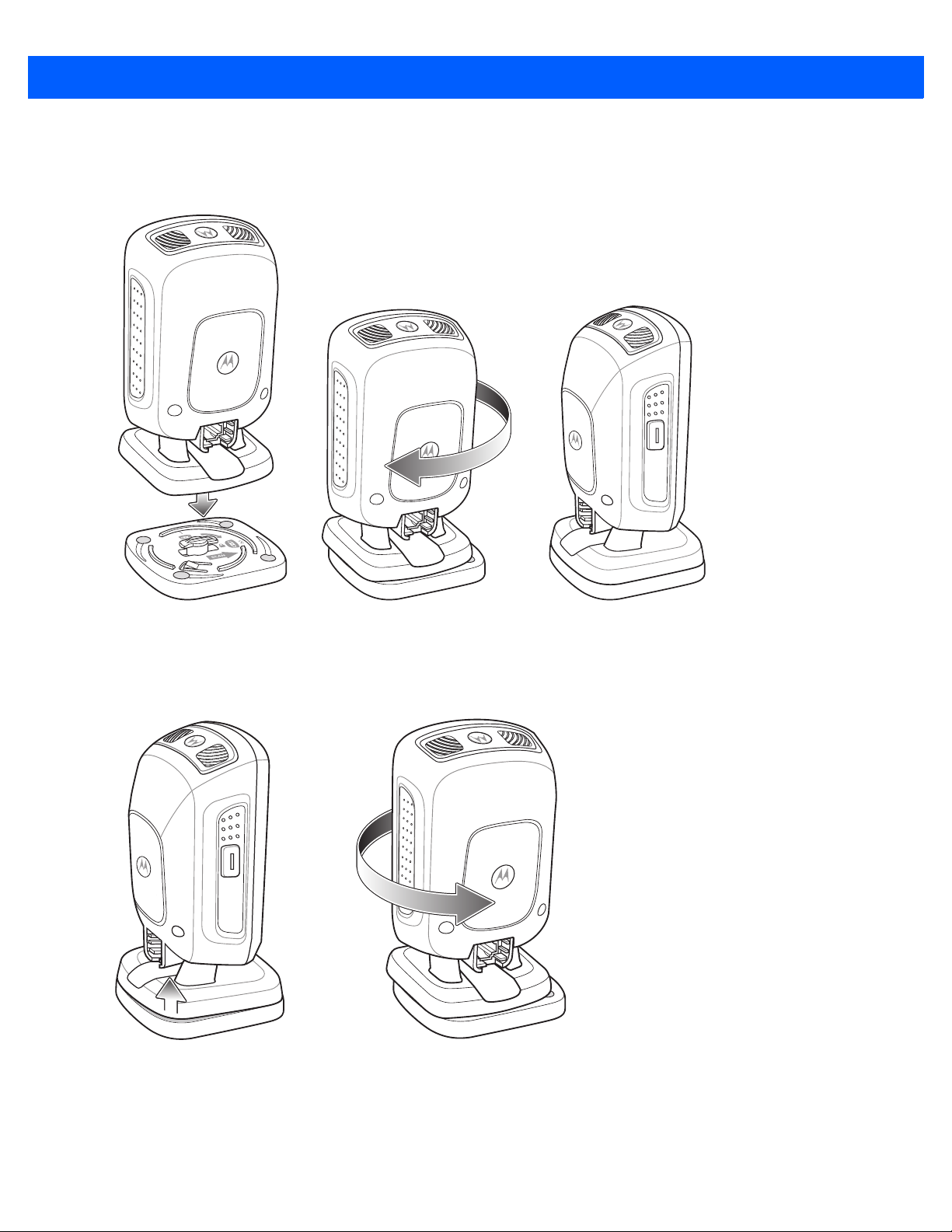
1 - 6 DS9208-1D Product Reference Guide
2. Tighten the screws to secure the bracket to the counter or desktop.
3. To insert the scanner into the Locking Mount Bracket, place the scanner onto the bracket and turn it 1/4
revolution clockwise until you hear a click and the scanner faces its final position.
Figure 1-6
Inserting the DS9208-1D into the Locking Mount Bracket
4. To remove the scanner from the Locking Mount Bracket, lift the scanner, pull up slightly on the scanner
with particular emphasis on the right rear corner (where the locking mechanism is) and turn
counter-clockwise until the scanner is released.
Figure 1-7
Removing the DS9208-1D from the Locking Mount Bracket

Getting Started 1 - 7
Accessories
Required Accessories
The digital scanner ships with the DS9208 Quick Start Guide. Also order an interface cable for the appropriate
interface, and a universal power supply if the interface requires this. For additional items, contact a local
Motorola representative or business par tner.
Optional Accessories
Contact Motorola to purchase the following accessories for the DS9208-1D:
•
Wall Mount Bracket (see Wall Mount Bracket on page 1-4 for installation instructions)
•
Locking Mount Bracket (see Locking Mount Bracket on page 1-5 for installation instructions)
Electronic Article Surveillance (EAS) (Optional)
Because there are several Checkpoint EAS systems available, your local Checkpoint representative should
connect the digital scanner to the Checkpoint EAS system and tune the system. To contact your local
Checkpoint representative inside the U.S. call 800-257-5540, ext. 4300. Outside the U.S., call (609) 848-1800,
ext. 4300.

1 - 8 DS9208-1D Product Reference Guide
Mounting Templates
Use the following templates to facilitate the proper placement of brackets and screws.
Figure 1-8
Wall Mount Bracket Template
Figure 1-9
Locking Mount Bracket Template
40 mm
54 mm
49 mm
CHAPTER 2 DATA CAPTURE
Introduction
This chapter provides beeper and LED definitions, techniques involved in capturing bar codes, general
instructions and tips about scanning, and decode range information.
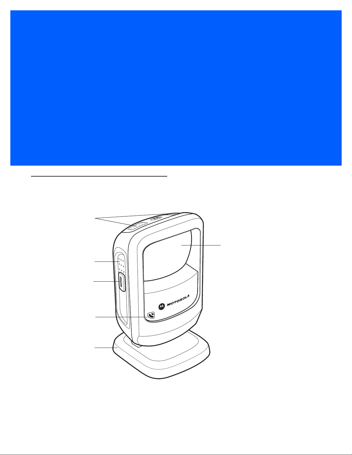
Figure 2-1
Parts
Decode LEDs
Exit Window
Adjustable Stand
Finger Grips
Trigger and
Volume Control
Beeper

2 - 2 DS9208-1D Product Reference Guide
Beeper Definitions
The digital scanner issues different beep sequences and patterns to indicate status. Table 2-1 defines beep
sequences that occur during both normal scanning and while programming the digital scanner.
Table 2-1
Beeper Definitions
Beeper Sequence Indication
Standard Use
Low/medium/high beeps Power up.
Short beep
(tone programmable)
A bar code symbol was decoded (if decode beeper is enabled).
4 low beeps Transmission error.
5 low beeps Conversion or format error.
Low/low/low/extra low beeps RS-232 receive error.
High beep The digital scanner detected a <BEL> character over RS-232.
Parameter Menu Scanning
High/low beeps Input error; incorrect bar code, programming sequence, or
Cancel
scanned.
Low/low beeps Keyboard parameter selected. Enter value using numeric bar codes.
High/low/high/low beeps Successful program exit with change in parameter setting.
ADF Programming
High/low beeps Enter another digit. Add leading zeros to the front if necessary.
Low/low beeps Enter another alphabetic character or scan the End of Message bar code.
High/high beeps ADF criteria or action is expected. Enter another criterion or action, or scan
the Save Rule bar code.
High/low/high/low beeps Rule saved. Rule entry mode exited.
High/low/low beeps All criteria or actions cleared for current rule, continue entering rule.
Low beep Delete last saved rule. The current rule is left intact.
Low/high/high beeps All rules are deleted.
Low/high/low/high beeps Out of rule memory. Erase some existing rules, then try to save rule again.
Low/high/low beeps Cancel rule entry. Rule entry mode exited because of an error or the user
asked to exit rule entry.
Low/high beeps Entry error, wrong bar code scanned, or c riteria/action list is too long for a rule.
Re-enter criterion or action.

Data Capture 2 - 3
Code 39 Buffering
High/low beeps New Code 39 data was entered into the buffer.
3 long high beeps Code 39 buffer is full.
High/low/high beeps The Code 39 buffer was erased.
Low/high/low beeps The Code 39 buffer was erased or there was an attempt to clear or transmit an
empty buffer.
Low/high beeps A successful transmission of buffered data.
Host Specific
USB only
Low/medium/high beeps
upon scanning a USB device
type
Communication with the host must be established before the digital scanner
can operate at the highest power level.
Low/medium/high beeps
occur more than once
The USB host can put the digital scanner in a state where power to the
scanner is cycled on and off more than once. This is normal and usually
happens when the PC cold boots.
RS-232 only
1 short high beep A <BEL> character is received and Beep on <BEL> is enabled.
Table 2-1
Beeper Definitions (Continued)
Beeper Sequence Indication

2 - 4 DS9208-1D Product Reference Guide
Selecting Beeper Volume using Trigger
The digital scanner emits a short beep when it successfully reads a bar code. To change the volume of the
beep either scan the appropriate bar cod e in Beeper Volume on page 4-7, or use the trigger as follows:
1. Press and hold the trigger for an extended period of time (5 seconds by default - see Volume Adjustment
Trigger Timeout on page 4-8 to change this). The digital scanner cycles through three settings (High,
Medium, Low) emitting a 2-beep tone at each setting.
2. To select a particular setting, release the trigger after you hear the desired 2-beep tone.
LED Definitions
In addition to beep sequences, the digital scanner uses a two-color LED to indicate st atus. Table 2-2 defines
LED colors that display during scanning.
Table 2-2
Standard LED Definitions
LED Indication
Presentation Mode
Green The scanner is on and ready to scan.
Momentarily Off A bar code was successfully decoded.
Red Transmission error, conversion or format error, or RS-232 receive error.
Off No power is applied to the digital scanner, or the scanner is in low power mode.
Trigger Mode
Green A bar code was successfully decoded.
Red Transmission error, conversion or format error, or RS-232 receive error.
Off No power is applied to the digital scanner, or the scanner is on and ready to scan.
Parameter Programming
Green Number expected. Enter value using numeric bar codes.
Successful program exit with change in parameter setting.
Red Input error: incorrect bar code, programming sequence, or Cancel scanned.
ADF Programming
Green Enter another digit. Add leading zeros to the front if necessary.
Enter another alphabetic character or scan the
End of Message
bar code.
All criteria or actions cleared for current rule, continue entering rule.
Delete last saved rule. The current rule is left intact.
All rules deleted.
Blinking Green Enter another criterion or action, or scan the
Save Rule
bar code.
Green after Blinking Rule saved. Rule entry mode exited.
Cancel rule entry. Rule entry mode exited because of an error or the user asked to
exit rule entry .
 Loading...