


SPLIT-TYPE, HEAT PUMP AIR CONDITIONERS
SPLIT-TYPE, AIR CONDITIONERS
May 2008
No. OC328
REVISED EDITION-B
SERVICE MANUAL
Indoor unit [Model names]
PCA-RP50GA
PCA-RP50GA2
PCA-RP60GA
PCA-RP71GA
PCA-RP100GA
PCA-RP125GA
PCA-RP140GA
PCH-P50GAH
PCH-P60GAH
PCH-P71GAH
PCH-P100GAH
PCH-P125GAH
PCH-P140GAH
[Service Ref.]
PCA-RP50GA PCA-RP50GA#1 PCA-RP50GA2 PCA-RP50GA2#1 PCA-RP60GA PCA-RP60GA#1 PCA-RP71GA PCA-RP71GA#1 PCA-RP100GA PCA-RP100GA#1 PCA-RP125GA PCA-RP125GA#1 PCA-RP140GA PCA-RP140GA#1
PCH-P50GAH
PCH-P60GAH
PCH-P71GAH
PCH-P100GAH
PCH-P125GAH
PCH-P140GAH
Revision :
•PCA-RP50~140GA(2)#1 are added in REVISED EDITION-B.
•RoHS PARTS LIST added.
•Some descriptions have been modified.
•Please void OC328 REVISED EDITION-A
NOTE:
•This manual describes only service data of the indoor units.
•RoHS compliant products have <G> mark on the spec name plate.
•For servicing of RoHS compliant products, refer to the RoHS Parts List.
CONTENTS
|
|
|
1. TECHNICAL CHANGES |
...................................... |
||||||||
|
|
|
|
|
|
|
2 |
|||||
|
|
|
|
|
|
|
............................................... |
|||||
|
|
|
2. REFERENCE MANUAL |
|
|
|
|
2 |
||||
|
|
|
|
|
|
|
................................... |
3 |
||||
|
|
|
3. SAFETY PRECAUTION |
|
|
|
|
|||||
|
|
|
4. PART NAMES AND FUNCTIONS |
.................... |
||||||||
|
|
|
|
|
7 |
|||||||
|
|
|
5. |
|
|
............................................ |
9 |
|||||
|
|
|
SPECIFICATIONS |
|
|
|
|
|
||||
INDOOR UNIT |
Model name |
6. |
NOISE CRITERION CURVES........................13 |
|||||||||
|
|
|
|
|
|
..................... |
15 |
|||||
|
|
indication |
7. OUTLINES AND DIMENSIONS |
|
||||||||
|
|
8. |
WIRING DIAGRAM |
................................................. |
|
|||||||
|
|
|
|
|
|
|
|
19 |
||||
|
|
|
9. |
REFRIGERANT SYSTEM DIAGRAM....................20 |
||||||||
|
|
|
|
|
|
|
................................... |
21 |
||||
|
|
|
10. TROUBLESHOOTING |
|
|
|
||||||
|
|
|
11. SPECIAL FUNCTION.....................................33 |
|||||||||
TEMP. |
ON/OFF |
|
12. DISASSEMBLY PROCEDURE |
....................... |
|
|||||||
|
|
|
|
|||||||||
|
|
|
|
|
36 |
|||||||
|
|
|
13. |
PARTS LIST |
.................................................... |
|
||||||
|
|
|
|
|
|
|
|
|
41 |
|||
|
|
|
14. |
RoHS PARTS LIST |
......................................... |
|
||||||
|
|
|
|
|
|
|
50 |
|||||
REMOTE CONTROLLER
1 
 TECHNICAL CHANGES
PCA-RP50GA(2)  PCA-RP50GA(2)#1
PCA-RP60GA PCA-RP60GA#1
PCA-RP71GA  PCA-RP71GA#1
PCA-RP100GA PCA-RP100GA#1
PCA-RP125GA  PCA-RP125GA#1
PCA-RP140GA PCA-RP140GA#1
INDOOR CONTROLLER BOARD(I.B.) has been changed.
2 |
|
REFERENCE MANUAL |
|
|
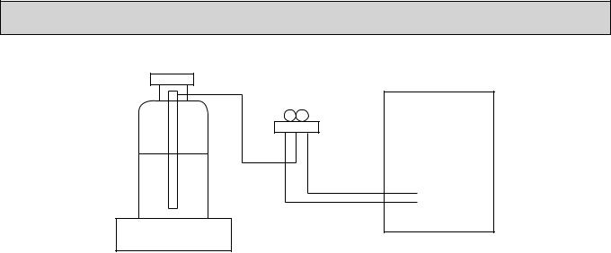
2-1. OUTDOOR UNIT’S SERVICE MANUAL |
|
|
||
|
|
|
||
Service Ref. |
Service Manual No. |
|
||
|
|
|
||
|
|
|
||
MXZ-8A140VA / VA1/ VA2 / VA3 |
OC316 |
|
||
SUZ-KA50/60/71VA(1).TH |
OC322 |
|
||
SUZ-KA50/60/71VA(1).TH-A |
OC323 |
|
||
PUHZ-RP35/50/60/71/100/125/140VHA(1) |
OC334 |
|
||
PUHZ-RP100/125/140YHA |
|
|||
|
|
|||
PUHZ-RP71/100/125/140VHA(1)-A |
OC337 |
|
||
PUHZ-RP200/250YHA(1)(2) |
OC338 |
|
||
PUHZ-RP200/250YHA(1)-A |
OC339 |
|
||
PU(H)-P • VGAA.UK |
OC336 |
|
||
PU(H)-P • YGAA.UK |
|
|||
|
|
|||
PUHZ-P100/125/140VHA.UK |
OC359 |
|
||
PUHZ-RP35/50/60/71/100/125/140VHA2(1) |
|
|
||
PUHZ-RP100/125/140YHA2(1) |
OC374 |
|
||
PUHZ-RP35/50/60/71/100VHA3 |
|
|||
|
|
|||
PUHZ-RP100YHA3 |
|
|
||
PU(H)-P71/100VHA(1).UK |
OC379 |
|
||
PU(H)-P100/125/140YHA(1).UK |
|
|||
|
|
|||
PUHZ-P100/125/140VHA2(1).UK |
OCH415 / OCB415 |
|
||
PUHZ-RP71/100/125/140VHA2-A |
OCH422 / OCB422 |
|
||
PUHZ-RP100/125/140YHA2-A |
|
|||
|
|
|||
PUHZ-BP100/125/140VHA-A |
OCH423 / OCB423 |
|
||
PUHZ-BP200/250YHA-A |
|
|||
|
|
|||
PUHZ-P200/250YHA2 |
OCH424 / OCB424 |
|
||
PUHZ-HRP71/100VHA |
OCH425 / OCB425 |
|
||
PUHZ-HRP100/125YHA |
|
|||
|
|
|||
PUHZ-RP200/250YHA2 |
OCH428 / OCB428 |
|
||
2-2. TECHNICAL DATA BOOK |
|
|
||
|
|
|||
Series (Outdoor unit) |
Manual No. |
|
||
|
|
|
||
PUHZ-RP • HA(-A) |
OCS01 |
|
||
PU(H)-P • GAA.UK |
OCS02 |
|
||
SUZ-KA • VA |
OCS03 |
|
||
PUHZ-RP • HA2 |
OCS05 |
|
||
PUHZ-P • HA |
OCS06 |
|
||
PU(H)-P • HA |
OCS07 |
|
||
PUHZ-P • VHA2, PUHZ-P • YHA |
OCS08 |
|
||
PUHZ-RP • HA2-A |
OCS09 |
|
||
PUHZ-BP • HA |
OCS10 |
|
||
PUHZ-HRP • HA |
OCS11 |
|
||
2
3 
 SAFETY PRECAUTION
3-1. ALWAYS OBSERVE FOR SAFETY
Before obtaining access to terminal, all supply circuits must be disconnected.
3-2. CAUTIONS RELATED TO NEW REFRIGERANT
Cautions for units utilising refrigerant R407C
Do not use the existing refrigerant piping.
The old refrigerant and lubricant in the existing piping contains a large amount of chlorine which may cause the lubricant deterioration of the new unit.
Use “low residual oil piping”
If there is a large amount of residual oil (hydraulic oil, etc.) inside the piping and joints, deterioration of the lubricant will result.
Store the piping to be used during installation indoors with keep both ends sealed until just before brazing.
(Store elbows and other joints in a plastic bag.)
If dust, dirt, or water enters the refrigerant cycle, deterioration of the oil and compressor trouble may result.
Use ESTER , ETHER or HAB as the lubricant to coat flares and flange connection parts.
If large amount of mineral oil enter, that can cause deterioration of refrigerant oil etc.
Use liquid refrigerant to charge the system.
If gas refrigerant is used to seal the system, the composition of the refrigerant in the cylinder will change and performance may drop.
Do not use a refrigerant other than R407C.
If another refrigerant (R22, etc.) is used, the chlorine in the refrigerant may cause the lubricant deterioration.
Use a vacuum pump with a reverse flow check valve.
The vacuum pump oil may flow back into the refrigerant cycle and cause the lubricant deterioration.
Ventilate the room if refrigerant leaks during operation. If refrigerant comes into contact with a flame, poisonous gases will be released.
3
[1] Cautions for service
·After recovering the all refrigerant in the unit, proceed to working. ·Do not release refrigerant in the air.
·After completing the repair service, recharge the cycle with the specified amount of liquid refrigerant.
[2]Refrigerant recharging
(1)Refrigerant recharging process 1Direct charging from the cylinder.
·R407C cylinder are available on the market has a syphon pipe. ·Leave the syphon pipe cylinder standing and recharge it.
(By liquid refrigerant)
Unit
Gravimeter
(2) Recharge in refrigerant leakage case
·After recovering the all refrigerant in the unit, proceed to working. ·Do not release the refrigerant in the air.
·After completing the repair service, recharge the cycle with the specified amount of liquid refrigerant.
[3] Service tools
Use the below service tools as exclusive tools for R407C refrigerant.
No. |
Tool name |
Specifications |
|
1 |
Gauge manifold |
·Only for R407C. |
|
|
|
·Use the existing fitting SPECIFICATIONS. (UNF7/16) |
|
|
|
·Use high-tension side pressure of 3.43MPa·G or over. |
|
2 |
Charge hose |
·Only for R407C. |
|
|
|
·Use pressure performance of 5.10MPa·G or over. |
|
3 |
Electronic scale |
|
— |
4 |
Gas leak detector |
·Use the detector for R134a or R407C. |
|
5 |
Adapter for reverse flow check. |
·Attach on vacuum pump. |
|
6 |
Refrigerant charge base. |
|
— |
7 |
Refrigerant cylinder. |
·For R407C |
·Top of cylinder (Brown) |
|
|
·Cylinder with syphon |
|
8 |
Refrigerant recovery equipment. |
|
— |
4
CAUTIONS RELATED TO NEW REFRIGERANT
Cautions for units utilising refrigerant R410A
Use new refrigerant pipes.
In case of using the existing pipes for R22, be careful with the followings.
·For RP60/71VHA3 and RP100/125/140, be sure to perform replacement operation before test run.
·Change flare nut to the one provided with this product. Use a newly flared pipe.
·Avoid using thin pipes.
Make sure that the inside and outside of refrigerant piping is clean and it has no contamination such as sulfur hazardous for use, oxides, dirt, shaving particles, etc.
In addition, use pipes with specified thickness.
Contamination inside refrigerant piping can cause deterioration of refrigerant oil etc.
Store the piping to be used during installation indoors and keep both ends of the piping sealed until just before brazing. (Leave elbow joints, etc. in their packaging.)
If dirt, dust or moisture enter into refrigerant cycle, that can cause deterioration of refrigerant oil or malfunction of compressor.
Use ester oil, ether oil or alkylbenzene oil (small amount) as the refrigerant oil applied to flares and flange connections.
If large amount of mineral oil enter, that can cause deterioration of refrigerant oil etc.
Charge refrigerant from liquid phase of gas cylinder.
If the refrigerant is charged from gas phase, composition change may occur in refrigerant and the efficiency will be lowered.
Do not use refrigerant other than R410A.
If other refrigerant (R22 etc.) is used, chlorine in refrigerant can cause deterioration of refrigerant oil etc.
Use a vacuum pump with a reverse flow check valve.
Vacuum pump oil may flow back into refrigerant cycle and that can cause deterioration of refrigerant oil etc.
Use the following tools specifically designed for use with R410A refrigerant.
The following tools are necessary to use R410A refrigerant.
|
Tools for R410A |
|
Gauge manifold |
|
Flare tool |
Charge hose |
|
Size adjustment gauge |
Gas leak detector |
|
Vacuum pump adaptor |
Torque wrench |
|
Electronic refrigerant |
|
|
charging scale |
Keep the tools with care.
If dirt, dust or moisture enter into refrigerant cycle, that can cause deterioration of refrigerant oil or malfunction of compressor.
Do not use a charging cylinder.
If a charging cylinder is used, the composition of refrigerant will change and the efficiency will be lowered.
Ventilate the room if refrigerant leaks during operation. If refrigerant comes into contact with a flame, poisonous gases will be released.
[1]Cautions for service
(1)Perform service after collecting the refrigerant left in unit completely.
(2)Do not release refrigerant in the air.
(3)After completing service, charge the cycle with specified amount of refrigerant.
(4)When performing service, install a filter drier simultaneously. Be sure to use a filter drier for new refrigerant.
[2]Additional refrigerant charge
When charging directly from cylinder
·Check that cylinder for R410A on the market is syphon type.
·Charging should be performed with the cylinder of syphon stood vertically. (Refrigerant is charged from liquid phase.)
5
Unit
Gravimeter
[3] Service tools
Use the below service tools as exclusive tools for R410A refrigerant.
No. |
|
|
Specifications |
||
1 |
Gauge manifold |
·Only for R410A |
|
|
|
|
|
·Use the existing fitting specifications. (UNF1/2) |
|||
|
|
·Use high-tension side pressure of 5.3MPa·G or over. |
|||
2 |
Charge hose |
·Only for R410A |
|
|
|
|
|
·Use pressure performance of 5.09MPa·G or over. |
|||
3 |
Electronic scale |
|
|
|
|
|
|
|
|
||
4 |
Gas leak detector |
·Use the detector for R134a, R407C or R410A. |
|||
5 |
Adaptor for reverse flow check |
·Attach on vacuum pump. |
|||
6 |
Refrigerant charge base |
|
|
|
|
|
|
|
|
||
7 |
Refrigerant cylinder |
·Only for R410A |
Top of cylinder (Pink) |
||
|
|
|
Cylinder with syphon |
||
8 |
Refrigerant recovery equipment |
|
|
|
|
|
|
|
|
||
6
4 
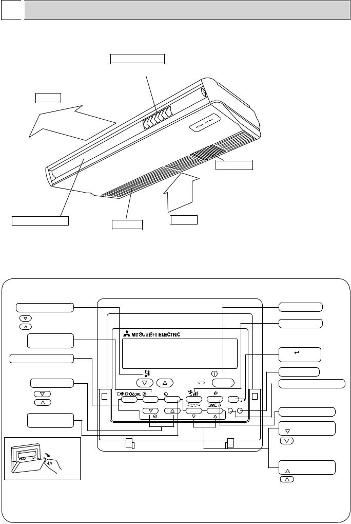
 PART NAMES AND FUNCTIONS
Indoor Unit
Left/right guide vanes
Air outlet
Change the direction of airflow from the horizontal blower.
Long-life filter
Removes dust and foreign matter from air coming in through the grille (Recommended cleaning interval : Approx, every 2,500 operating hours)
Up/down guide vanes |
Air intake |
Change the direction of airflow from the |
Intake grille |
|
|
vertical blower. |
|
Remote controller
Once the controls are set, the same operation mode can be repeated by simply pressing the ON/OFF button.
Operation buttons
Set Temperature buttons |
|
|
|
Down |
|
|
|
Up |
|
|
|
Timer Menu button |
|
|
|
(Monitor/Set button) |
|
|
|
Mode button (Return button) |
|
|
|
|
|
TEMP. |
|
Set Time buttons |
|
|
|
Back |
|
MENU |
ON/OFF |
Ahead |
BACK |
MONITOR/SET |
DAY |
|
|||
Timer On/Off button |
PAR-21MAA |
CLOCK |
|
(Set Day button) |
|
|
|
Opening the |
|
|
|
door. |
|
|
|
|
|
ON/OFF button |
||
|
|
Fan Speed button |
||
|
|
Filter |
button |
|
|
|
(<Enter> button) |
||
|
ON/OFF |
Test Run button |
||
|
|
|
|
|
|
|
Check button (Clear button) |
||
|
FILTER |
|
|
|
|
CHECK |
TEST |
|
|
OPERATION |
CLEAR |
Airflow Up/Down button |
||
|
|
|
||
|
|
Louver button |
||
|
|
( |
|
Operation button) |
|
|
|
|
To preceding operation |
|
|
|
|
number. |
|
|
Ventilation button |
||
|
|
( |
Operation button) |
|
|
|
|
|
To next operation number. |
7
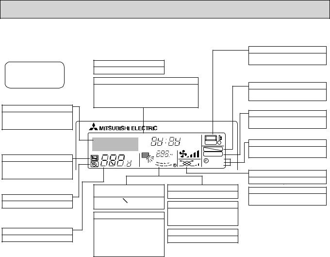
Display
For purposes of this explanation, all parts of the display are shown as lit. During actual operation, only the relevant items will be lit.
Identifies the current operation
Shows the operating mode, etc.
*Multilanguage display is supported.
“Centrally Controlled” indicator
Indicates that operation of the remote controller has been prohibited by a master controller.
“Timer Is Off” indicator
Indicates that the timer is off.
Temperature Setting
Shows the target temperature.
Day-of-Week
Shows the current day of the week.
Time/Timer Display
Shows the current time, unless the simple or Auto Off timer is set.
If the simple or Auto Off timer is set, shows the time remaining.
TIME SUN MON TUE WED THU FRI SAT
TIMER |
Hr |
ON |
AFTER |
AFTER |
OFF |
ERROR CODE |
|
FUNCTION |
°F°C |
|
FILTER |
°F°C |
|
|
|
WEEKLY |
|
ONLY1Hr. |
|
SIMPLE |
|
AUTO OFF |
Up/Down Air Direction indicator
The indicator shows the direction of the outcoming airflow.
“One Hour Only” indicator
Displayed if the airflow is set to weak and downward during COOL or DRY mode. (Operation varies according to model.)
The indicator goes off after one hour, at which time the airflow direction also changes.
Room Temperature display
Shows the room temperature.
Louver display
Indicates the action of the swing louver. Does not appear if the louver is stationary.
 (Power On indicator)
Indicates that the power is on.
“Sensor” indication
Displayed when the remote controller sensor is used.
“Locked” indicator
Indicates that remote controller buttons have been locked.
“Clean The Filter” indicator
Comes on when it is time to clean the filter.
Timer indicators
The indicator comes on if the corresponding timer is set.
Fan Speed indicator
Shows the selected fan speed.
Ventilation indicator
Appears when the unit is running in Ventilation mode.
Caution
Only the Power on indicator lights when the unit is stopped and power supplied to the unit.
If you press a button for a feature that is not installed at the indoor unit, the remote controller will display the “Not Available” message.
If you are using the remote controller to drive multiple indoor units, this message will appear only if he feature is not present at the parent unit.
When power is turned ON for the first time, it is normal that “PLEASE WAIT” is displayed on the room temperature indication (For max. 2minutes). Please wait until this “PLEASE WAIT” indication disappear then start the operation.
8
5 
 SPECIFICATIONS
|
Service Ref. |
|
|
|
|
Mode |
|
|
|
|
Power supply(phase, cycle, voltage) |
kW |
||
|
|
Input |
|
|
|
|
Running current |
|
A |
|
|
Starting current |
|
A |
UNIT |
External finish |
|
|
|
Heat exchanger |
|
|
||
|
|
|
||
INDOOR |
Fan |
Fan(drive) x No. |
|
kW |
|
Fan motor output |
|
||
|
|
|
||
|
|
Airflow(Low-Medium2-Medium1-High) */min(CFM) |
||
|
|
External static pressure |
Pa(mmAq) |
|
|
Operation control & Thermostat |
|
dB |
|
|
Noise level(Low-Medium2-Medium1-High) |
|||
|
Unit drain pipe I.D. |
|
mm(in.) |
|
|
Dimensions |
W |
mm(in.) |
|
|
|
|
D |
mm(in.) |
|
|
|
H |
mm(in.) |
|
Weight |
|
|
kg(lbs) |
|
Service Ref. |
|
|
||
|
Mode |
|
|
|
|
|
Power supply(phase, cycle, voltage) |
|
|||
|
|
Input |
|
kW |
|
|
|
Running current |
|
A |
|
|
|
Starting current |
|
A |
|
UNIT |
External finish |
|
|
||
Heat exchanger |
|
|
|||
|
|
|
|||
INDOOR |
Fan |
Fan(drive) x No. |
|
|
|
|
Fan motor output |
|
kW |
||
|
|
Airflow(Low-Medium2-Medium1-High) */min(CFM) |
|||
|
|
External static pressure |
Pa(mmAq) |
||
|
Operation control & Thermostat |
|
|
||
|
Noise level(Low-Medium2-Medium1-High) |
dB |
|||
|
Unit drain pipe I.D. |
|
mm(in.) |
||
|
Dimensions |
|
W |
mm(in.) |
|
|
|
|
|
D |
mm(in.) |
|
Weight |
|
|
H |
mm(in.) |
|
|
|
|
kg(lbs) |
|
|
Service Ref. |
|
|
|
|
Mode |
|
|
|
|
Power supply(phase, cycle, voltage) |
|
||
|
|
Input |
|
kW |
|
|
Running current |
|
A |
|
|
Starting current |
|
A |
UNIT |
External finish |
|
|
|
Heat exchanger |
|
|
||
|
|
|
||
INDOOR |
Fan |
Fan(drive) x No. |
|
|
|
Fan motor output |
|
kW |
|
|
|
|
||
|
|
Airflow(Low-Medium2-Medium1-High) */min(CFM) |
||
|
|
External static pressure |
Pa(mmAq) |
|
|
Operation control & Thermostat |
|
|
|
|
Noise level(Low-Medium2-Medium1-High) |
dB |
||
|
Unit drain pipe I.D. |
|
mm(in.) |
|
|
Dimensions |
W |
mm(in.) |
|
|
|
|
D |
mm(in.) |
|
Weight |
|
H |
mm(in.) |
|
|
|
kg(lbs) |
|
|
Service Ref. |
|
|
||
|
Mode |
|
|
|
|
|
Power supply(phase, cycle, voltage) |
|
|||
|
|
Input |
|
kW |
|
|
|
Running current |
|
A |
|
|
|
Starting current |
|
A |
|
|
External finish |
|
|
||
UNIT |
Heat exchanger |
|
|
||
Fan |
Fan(drive) x No. |
|
|
||
|
|
|
|||
INDOOR |
|
Fan motor output |
|
kW |
|
|
Airflow(Low-Medium2-Medium1-High) */min(CFM) |
||||
|
External static pressure |
Pa(mmAq) |
|||
Operation control & Thermostat |
|
|
|||
|
Noise level(Low-Medium2-Medium1-High) |
dB |
|||
|
Unit drain pipe I.D. |
|
mm(in.) |
||
|
Dimensions |
|
W |
mm(in.) |
|
|
|
|
|
D |
mm(in.) |
|
Weight |
|
|
H |
mm(in.) |
|
|
|
|
kg(lbs) |
|
Cooling |
PCA-RP50GA, PCA-RP50GA#1 |
Heating |
|
0.09 |
Single phase, 50Hz, 230V |
0.09 |
|
0.41 |
0.41 |
1.20 |
1.20 |
Munsell 0.70Y 8.59/0.97 Plate fin coil
Sirocco fan (direct) x 2 0.054 10-11-12-13(355-390-425-460) 0(direct blow)
Remote controller & built-in 37-38-40-42
26(1) 1,000(39-3/8) 680(26-3/4) 210(8-1/4) 27(60)
PCA-RP50GA2, PCA-RP50GA2#1
Cooling |
|
Heating |
0.12 |
Single phase, |
50Hz, 230V |
|
0.12 |
|
0.53 |
|
0.53 |
1.27 |
|
1.27 |
Munsell 0.70Y 8.59/0.97 Plate fin coil
Sirocco fan (direct) x 3 0.070 14-15-16-18(495-530-565-635) 0(direct blow)
Remote controller & built-in 37-39-41-43
26(1) 1,310(51-9/16) 680(26-3/4) 210(8-1/4) 34(75)
Cooling |
PCA-RP60GA, PCA-RP60GA#1 |
Heating |
|
0.12 |
Single phase, 50Hz, 230V |
0.12 |
|
0.53 |
0.53 |
1.27 |
1.27 |
|
Munsell 0.70Y 8.59/0.97 |
|
Plate fin coil |
|
Sirocco fan (direct) x 3 |
|
0.070 |
|
14-15-16-18(495-530-565-635) |
|
0(direct blow) |
|
Remote controller & built-in |
|
37-39-41-43 |
|
26(1) |
|
1,310(51-9/16) |
|
680(26-3/4) |
|
210(8-1/4) |
|
34(75) |
Cooling |
PCA-RP71GA, PCA-RP71GA#1 |
|
|
Heating |
|
0.12 |
Single phase, |
50Hz, 230V |
|
0.12 |
|
0.53 |
|
0.53 |
1.27 |
|
1.27 |
Munsell 0.70Y 8.59/0.97 Plate fin coil
Sirocco fan (direct) x 3 0.070 14-15-16-18(495-530-565-635) 0(direct blow)
Remote controller & built-in 37-39-41-43
26(1) 1,310(51-9/16) 680(26-3/4) 210(8-1/4) 34(75)
9
|
Service Ref. |
|
|
||
|
Mode |
|
|
|
|
|
Power supply(phase, cycle, voltage) |
kW |
|||
|
|
Input |
|
||
|
|
Running current |
|
A |
|
|
|
Starting current |
|
A |
|
|
External finish |
|
|
||
UNIT |
Heat exchanger |
|
|
||
Fan |
Fan(drive) x No. |
|
kW |
||
|
|
||||
INDOOR |
|
Fan motor output |
|
||
|
Airflow(Low-Medium2-Medium1-High) |
*/min(CFM) |
|||
|
|
||||
|
|
External static pressure |
Pa(mmAq) |
||
|
Operation |
control & Thermostat |
|
dB |
|
|
Noise level(Low-Medium2-Medium1-High) |
||||
|
Unit drain pipe I.D. |
|
mm(in.) |
||
|
Dimensions |
W |
mm(in.) |
||
|
|
|
|
D |
mm(in.) |
|
|
|
|
H |
mm(in.) |
|
Weight |
|
|
|
kg(lbs) |
|
Service Ref. |
|
|
||
|
|
|
|||
|
Mode |
|
|
|
|
|
Power supply(phase, cycle, voltage) |
|
|||
|
|
Input |
|
kW |
|
|
|
Running current |
|
A |
|
|
|
Starting current |
|
A |
|
UNIT |
External finish |
|
|
||
Heat exchanger |
|
|
|||
|
|
|
|||
INDOOR |
Fan |
Fan(drive) x No. |
|
|
|
|
Fan motor output |
|
kW |
||
|
|
Airflow(Low-Medium2-Medium1-High) */min(CFM) |
|||
|
|
External static pressure |
Pa(mmAq) |
||
|
Operation control & Thermostat |
|
|
||
|
Noise level(Low-Medium2-Medium1-High) |
dB |
|||
|
Unit drain pipe I.D. |
|
mm(in.) |
||
|
Dimensions |
|
W |
mm(in.) |
|
|
|
|
|
D |
mm(in.) |
|
Weight |
|
|
H |
mm(in.) |
|
|
|
|
kg(lbs) |
|
|
Service Ref. |
|
|
||
|
Mode |
|
|
|
|
|
Power supply(phase, cycle, voltage) |
|
|||
|
|
Input |
|
kW |
|
|
|
Running current |
|
A |
|
|
|
Starting current |
|
A |
|
|
External finish |
|
|
||
UNIT |
Heat exchanger |
|
|
||
Fan |
Fan(drive) x No. |
|
|
||
|
|
|
|||
INDOOR |
|
Fan motor output |
|
kW |
|
|
Airflow(Low-Medium2-Medium1-High) */min(CFM) |
||||
|
|
||||
|
|
External static pressure |
Pa(mmAq) |
||
|
Operation control & Thermostat |
|
|
||
|
Noise level(Low-Medium2-Medium1-High) |
dB |
|||
|
Unit drain pipe I.D. |
|
mm(in.) |
||
|
Dimensions |
W |
mm(in.) |
||
|
|
|
|
D |
mm(in.) |
|
Weight |
|
|
H |
mm(in.) |
|
|
|
|
kg(lbs) |
|
PCA-RP100GA, PCA-RP100GA#1
Cooling |
Heating |
0.15 |
Single phase, 50Hz, 230V |
0.15 |
|
0.69 |
0.69 |
1.48 |
1.48 |
Munsell 0.70Y 8.59/0.97
Plate fin coil
Sirocco fan (direct) x 3
0.090
20-21-23-25(705-740-810-885)
0(direct blow)
Remote controller & built-in
40-41-43-45
26(1)
1,310(51-9/16)
680(26-3/4)
270(10-5/8)
37(82)
PCA-RP125GA, PCA-RP125GA#1
Cooling |
|
Heating |
0.22 |
Single phase, |
50Hz, 230V |
|
0.22 |
|
1.01 |
|
1.01 |
2.20 |
|
2.20 |
Munsell 0.70Y 8.59/0.97 Plate fin coil
Sirocco fan (direct) x 4 0.150
27-30-32-34(955-1,060-1,130-1,200)
0(direct blow) Remote controller & built-in
41-43-45-46 26(1)
1,620(63-3/4)
680(26-3/4) 270(10-5/8)
43(95)
PCA-RP140GA, PCA-RP140GA#1
Cooling |
Heating |
0.22 |
Single phase, 50Hz, 230V |
0.22 |
|
1.01 |
1.01 |
2.20 |
2.20 |
Munsell 0.70Y 8.59/0.97 Plate fin coil
Sirocco fan (direct) x 4 0.150
27-30-32-34(955-1,060-1,130-1,200) 0(direct blow)
Remote controller & built-in 42-44-46-48
26(1) 1,620(63-3/4) 680(26-3/4) 270(10-5/8) 45(99)
10
|
|
|
|
|
|
|
|
|
|
|
|
|
|
|
|
|
Service Ref. |
|
|
|
PCH-P50GAH |
||
|
Mode |
|
|
|
Cooling |
|
Heating |
|
Power supply(phase, cycle, voltage) |
|
|
Single phase, |
50Hz, 230V |
||
|
|
Input |
+1 |
kW |
0.09 |
|
0.09<1.29> |
|
|
Running current |
+1 |
A |
0.41 |
|
0.41<5.61> |
|
|
Starting current |
+1 |
A |
1.20 |
|
1.20<5.61> |
|
External finish |
|
|
|
Munsell 0.70Y 8.59/0.97 |
||
UNIT |
Heat exchanger |
|
|
|
Plate fin coil |
||
Fan |
Fan(drive) x No. |
|
|
|
Sirocco fan (direct) x 2 |
||
INDOOR |
|
Fan motor output |
|
kW |
|
0.054 |
|
|
Airflow(Low-Medium2-Medium1-High) |
*/min(CFM) |
|
10-11-12-13(355-390-425-460) |
|||
|
External static pressure |
Pa(mmAq) |
|
0(direct blow) |
|||
Booster heater |
+1 |
kW |
|
<1.29> |
|||
|
|
||||||
|
Operation control & Thermostat |
|
|
Remote controller & built-in |
|||
|
Noise level(Low-Medium2-Medium1-High) |
dB |
|
37-38-40-42 |
|||
|
Unit drain pipe I.D. |
|
mm(in.) |
|
26(1) |
||
|
Dimensions |
W |
mm(in.) |
|
1,000(39-3/8) |
||
|
|
|
D |
mm(in.) |
|
680(26-3/4) |
|
|
|
|
H |
mm(in.) |
|
210(8-1/4) |
|
|
Weight |
|
|
kg(lbs) |
|
28.5(63) |
|
INDOOR UNIT
Service Ref.
Mode
Power supply(phase, cycle, voltage)
|
Input |
+1 |
kW |
|
Running current |
+1 |
A |
|
Starting current |
+1 |
A |
External finish |
|
|
|
Heat exchanger |
|
|
|
Fan |
Fan(drive) x No. |
|
|
|
Fan motor output |
|
kW |
|
Airflow(Low-Medium2-Medium1-High) |
*/min(CFM) |
|
|
External static pressure |
Pa(mmAq) |
|
Booster |
heater |
+1 |
kW |
Operation control & Thermostat |
|
||
Noise level(Low-Medium2-Medium1-High) |
dB |
||
Unit drain pipe I.D. |
|
mm(in.) |
|
Dimensions |
W |
mm(in.) |
|
|
|
D |
mm(in.) |
Weight |
|
H |
mm(in.) |
|
|
kg(lbs) |
|
Cooling |
PCH-P60GAH |
Heating |
|
0.12 |
Single phase, 50Hz, 230V |
0.12<1.93> |
|
0.53 |
0.53<8.39> |
1.27 |
1.27<8.39> |
Munsell 0.70Y 8.59/0.97
Plate fin coil
Sirocco fan (direct) x 3
0.070
14-15-16-18(495-530-565-635)
0(direct blow)
<1.93>
Remote controller & built-in
37-39-41-43
26(1)
1,310(51-9/16)
680(26-3/4)
210(8-1/4)
36(79)
|
Service Ref. |
|
|
|
PCH-P71GAH |
||
|
Mode |
|
|
|
Cooling |
|
Heating |
|
Power supply(phase, cycle, voltage) |
|
|
Single phase, |
50Hz, 230V |
||
|
|
Input |
+1 |
kW |
0.12 |
|
0.12<1.93> |
|
|
Running current |
+1 |
A |
0.53 |
|
0.53<8.39> |
|
|
Starting current |
+1 |
A |
1.27 |
|
1.27<8.39> |
|
External finish |
|
|
|
Munsell 0.70Y 8.59/0.97 |
||
UNIT |
Heat exchanger |
|
|
|
Plate fin coil |
||
Fan |
Fan(drive) x No. |
|
|
|
Sirocco fan (direct) x 3 |
||
INDOOR |
|
Fan motor output |
|
kW |
|
0.070 |
|
|
Airflow(Low-Medium2-Medium1-High) |
*/min(CFM) |
|
14-15-16-18(495-530-565-635) |
|||
|
External static pressure |
Pa(mmAq) |
|
0(direct blow) |
|||
Booster heater |
+1 |
kW |
|
<1.93> |
|||
|
|
||||||
|
Operation control & Thermostat |
|
|
Remote controller & built-in |
|||
|
Noise level(Low-Medium2-Medium1-High) |
dB |
|
37-39-41-43 |
|||
|
Unit drain pipe I.D. |
|
mm(in.) |
|
26(1) |
||
|
Dimensions |
W |
mm(in.) |
|
1,310(51-9/16) |
||
|
|
|
D |
mm(in.) |
|
680(26-3/4) |
|
|
|
|
H |
mm(in.) |
|
210(8-1/4) |
|
|
Weight |
|
|
kg(lbs) |
|
36(79) |
|
+1 : < > Shows the only booster heater rating.
11
|
Service Ref. |
|
|
|
|
Mode |
|
|
|
|
Power supply(phase, cycle, voltage) |
|
||
|
|
Input |
+1 |
kW |
|
|
Running current |
+1 |
A |
|
|
Starting current |
+1 |
A |
|
External finish |
|
|
|
UNIT |
Heat exchanger |
|
|
|
Fan |
Fan(drive) x No. |
|
|
|
|
|
|
||
INDOOR |
|
Fan motor output |
|
kW |
|
Airflow(Low-Medium2-Medium1-High) */min(CFM) |
|||
|
|
|||
|
|
External static pressure |
Pa(mmAq) |
|
|
Booster heater |
+1 |
kW |
|
|
Operation control & Thermostat |
|
||
|
Noise level(Low-Medium2-Medium1-High) |
dB |
||
|
Unit drain pipe I.D. |
|
mm(in.) |
|
|
Dimensions |
W |
mm(in.) |
|
|
|
|
D |
mm(in.) |
|
Weight |
|
H |
mm(in.) |
|
|
|
kg(lbs) |
|
|
Service Ref. |
|
|
|
|
Mode |
|
|
|
|
Power supply(phase, cycle, voltage) |
|
||
|
|
Input |
+1 |
kW |
|
|
Running current |
+1 |
A |
|
|
Starting current |
+1 |
A |
|
External finish |
|
|
|
UNIT |
Heat exchanger |
|
|
|
Fan |
Fan(drive) x No. |
|
|
|
|
|
|
||
INDOOR |
|
Fan motor output |
|
kW |
|
Airflow(Low-Medium2-Medium1-High) |
*/min(CFM) |
||
|
|
External static pressure |
Pa(mmAq) |
|
|
Booster |
heater |
+1 |
kW |
|
Operation control & Thermostat |
|
||
|
Noise level(Low-Medium2-Medium1-High) |
dB |
||
|
Unit drain pipe I.D. |
|
mm(in.) |
|
|
Dimensions |
W |
mm(in.) |
|
|
|
|
D |
mm(in.) |
|
Weight |
|
H |
mm(in.) |
|
|
|
kg(lbs) |
|
|
Service Ref. |
|
|
|
|
Mode |
|
|
|
|
Power supply(phase, cycle, voltage) |
|
||
|
|
Input |
+1 |
kW |
|
|
Running current |
+1 |
A |
|
|
Starting current |
+1 |
A |
|
External finish |
|
|
|
UNIT |
Heat exchanger |
|
|
|
Fan |
Fan(drive) x No. |
|
|
|
|
|
|
||
INDOOR |
Booster |
Fan motor output |
+1 |
kW |
heater |
kW |
|||
|
|
Airflow(Low-Medium2-Medium1-High) |
*/min(CFM) |
|
|
|
External static pressure |
Pa(mmAq) |
|
|
Operation control & Thermostat |
|
||
|
|
|||
|
Noise level(Low-Medium2-Medium1-High) |
dB |
||
|
Unit drain pipe I.D. |
|
mm(in.) |
|
|
Dimensions |
W |
mm(in.) |
|
|
|
|
D |
mm(in.) |
|
Weight |
|
H |
mm(in.) |
|
|
|
kg(lbs) |
|
+1 |
: < > Shows the only booster heater rating. |
|||
Cooling |
PCH-P100GAH |
|
|
Heating |
|
0.15 |
Single phase, |
50Hz, 230V |
|
0.15<2.48> |
|
0.69 |
|
0.69<10.78> |
1.48 |
|
1.48<10.78> |
Munsell 0.70Y 8.59/0.97 Plate fin coil
Sirocco fan (direct) x 3 0.090
20-21-23-25(705-740-810-885) 0(direct blow)
<2.48>
Remote controller & built-in
40-41-43-45 26(1)
1,310(51-9/16) 680(26-3/4) 270(10-5/8)
39.5(87)
Cooling |
PCH-P125GAH |
Heating |
|
0.22 |
Single phase, 50Hz, 230V |
0.22<2.76> |
|
1.01 |
1.01<12.00> |
2.20 |
2.20<12.00> |
Munsell 0.70Y 8.59/0.97
Plate fin coil
Sirocco fan (direct) x 4
0.150
27-30-32-34(955-1,060-1,130-1,200)
0(direct blow)
<2.76>
Remote controller & built-in
41-43-45-46
26(1)
1,620(63-3/4)
680(26-3/4)
270(10-5/8)
46(101)
Cooling |
PCH-P140GAH |
Heating |
|
0.22 |
Single phase, 50Hz, 230V |
0.22<2.76> |
|
1.01 |
1.01<12.00> |
2.20 |
2.20<12.00> |
Munsell 0.70Y 8.59/0.97
Plate fin coil
Sirocco fan (direct) x 4
0.150
27-30-32-34(955-1,060-1,130-1,200)
0(direct blow)
<2.76>
Remote controller & built-in
42-44-46-48
26(1)
1,620(63-3/4)
680(26-3/4)
270(10-5/8)
48(106)
12

6 
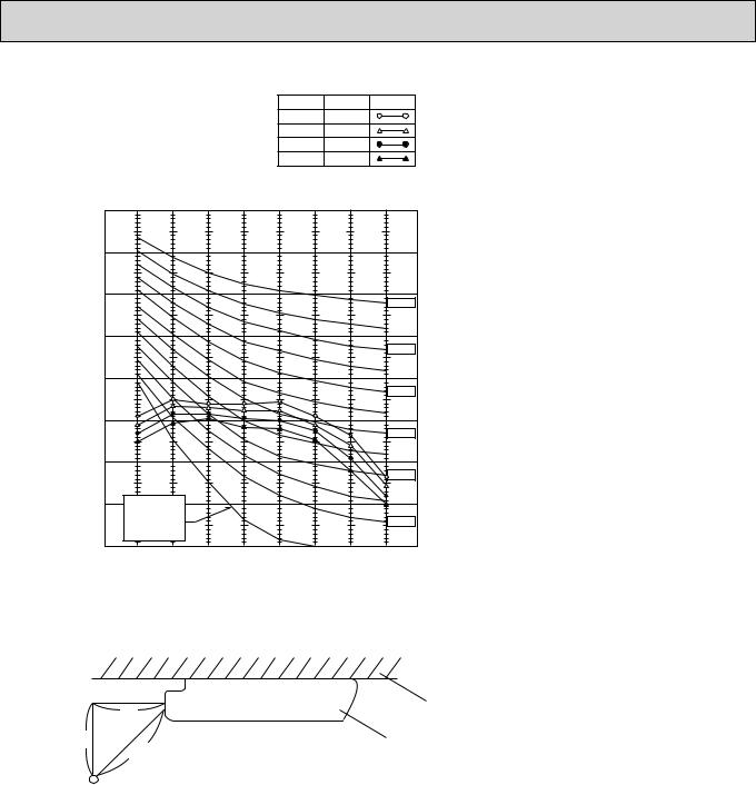
 NOISE CRITERION CURVES
PCA-RP50GA |
|
|
NOTCH |
SPL(dB) |
LINE |
||||
PCA-RP50GA#1 |
|
|
|
High |
42 |
|
|||
|
|
Medium1 |
40 |
|
|||||
PCH-P50GAH |
|
|
Medium2 |
38 |
|
||||
|
|
|
|
|
|
|
Low |
37 |
|
|
90 |
|
|
|
|
|
|
|
|
μbar) |
80 |
|
|
|
|
|
|
|
|
|
|
|
|
|
|
|
|
|
|
= 0.0002 |
70 |
|
|
|
|
|
|
|
NC-70 |
|
|
|
|
|
|
|
|
||
dB (0 dB |
60 |
|
|
|
|
|
|
|
|
LEVEL, |
|
|
|
|
|
|
|
|
NC-60 |
|
|
|
|
|
|
|
|
|
|
PRESSURE |
50 |
|
|
|
|
|
|
|
|
|
|
|
|
|
|
|
|
NC-50 |
|
|
|
|
|
|
|
|
|
|
|
SOUND |
40 |
|
|
|
|
|
|
|
|
|
|
|
|
|
|
|
|
NC-40 |
|
BAND |
30 |
|
|
|
|
|
|
|
|
OCTAVE |
|
|
|
|
|
|
|
|
|
|
|
|
|
|
|
|
|
NC-30 |
|
|
|
|
|
|
|
|
|
|
|
|
20 |
APPROXIMATE |
|
|
|
|
|
|
|
|
|
THRESHOLD OF |
|
|
|
|
|
|
|
|
|
HEARING FOR |
|
|
|
|
|
NC-20 |
|
|
|
CONTINUOUS |
|
|
|
|
|
||
|
|
NOISE |
|
|
|
|
|
|
|
|
10 |
63 |
125 |
250 |
500 |
1000 |
2000 |
4000 |
8000 |
|
|
||||||||
BAND CENTER FREQUENCIES, Hz
PCA-RP100GA |
|
|
NOTCH |
SPL(dB) |
LINE |
||||
PCA-RP100GA#1 |
|
|
High |
45 |
|
||||
|
Medium1 |
43 |
|
||||||
PCH-P100GAH |
|
|
Medium2 |
41 |
|
||||
|
|
|
|
|
|
|
Low |
40 |
|
|
90 |
|
|
|
|
|
|
|
|
μbar) |
80 |
|
|
|
|
|
|
|
|
|
|
|
|
|
|
|
|
|
|
= 0.0002 |
70 |
|
|
|
|
|
|
|
NC-70 |
|
|
|
|
|
|
|
|
||
dB (0 dB |
60 |
|
|
|
|
|
|
|
|
LEVEL, |
|
|
|
|
|
|
|
|
NC-60 |
|
|
|
|
|
|
|
|
|
|
PRESSURE |
50 |
|
|
|
|
|
|
|
|
|
|
|
|
|
|
|
|
NC-50 |
|
|
|
|
|
|
|
|
|
|
|
SOUND |
40 |
|
|
|
|
|
|
|
|
|
|
|
|
|
|
|
|
NC-40 |
|
BAND |
30 |
|
|
|
|
|
|
|
|
OCTAVE |
|
|
|
|
|
|
|
|
|
|
|
|
|
|
|
|
|
NC-30 |
|
|
|
|
|
|
|
|
|
|
|
|
20 |
APPROXIMATE |
|
|
|
|
|
|
|
|
|
THRESHOLD OF |
|
|
|
|
|
|
|
|
|
HEARING FOR |
|
|
|
|
|
NC-20 |
|
|
|
CONTINUOUS |
|
|
|
|
|
||
|
|
NOISE |
|
|
|
|
|
|
|
|
10 |
63 |
125 |
250 |
500 |
1000 |
2000 |
4000 |
8000 |
|
|
||||||||
BAND CENTER FREQUENCIES, Hz
PCA-RP50GA2 |
|
|
NOTCH |
SPL(dB) |
LINE |
||||
PCA-RP50GA2#1 |
|
|
|
High |
43 |
|
|||
|
|
Medium1 |
41 |
|
|||||
PCA-RP60/71GA |
|
|
|
||||||
|
|
Medium2 |
39 |
|
|||||
PCA-RP60/71GA#1 |
|
|
Low |
37 |
|
||||
PCH-P60/71GAH |
|
|
|
|
|
|
|||
|
90 |
|
|
|
|
|
|
|
|
μbar) |
80 |
|
|
|
|
|
|
|
|
|
|
|
|
|
|
|
|
|
|
= 0.0002 |
70 |
|
|
|
|
|
|
|
NC-70 |
|
|
|
|
|
|
|
|
||
dB (0 dB |
60 |
|
|
|
|
|
|
|
|
LEVEL, |
|
|
|
|
|
|
|
|
NC-60 |
|
|
|
|
|
|
|
|
|
|
PRESSURE |
50 |
|
|
|
|
|
|
|
|
|
|
|
|
|
|
|
|
NC-50 |
|
|
|
|
|
|
|
|
|
|
|
SOUND |
40 |
|
|
|
|
|
|
|
|
|
|
|
|
|
|
|
|
NC-40 |
|
BAND |
30 |
|
|
|
|
|
|
|
|
OCTAVE |
|
|
|
|
|
|
|
|
|
|
|
|
|
|
|
|
|
NC-30 |
|
|
|
|
|
|
|
|
|
|
|
|
20 |
APPROXIMATE |
|
|
|
|
|
|
|
|
|
THRESHOLD OF |
|
|
|
|
|
|
|
|
|
HEARING FOR |
|
|
|
|
|
NC-20 |
|
|
|
CONTINUOUS |
|
|
|
|
|
||
|
|
NOISE |
|
|
|
|
|
|
|
|
10 |
63 |
125 |
250 |
500 |
1000 |
2000 |
4000 |
8000 |
|
|
||||||||
BAND CENTER FREQUENCIES, Hz
PCA-RP125GA |
|
|
NOTCH |
SPL(dB) |
LINE |
||||
PCA-RP125GA#1 |
|
|
High |
46 |
|
||||
|
Medium1 |
45 |
|
||||||
PCH-P125GAH |
|
|
Medium2 |
43 |
|
||||
|
|
|
|
|
|
|
Low |
41 |
|
|
90 |
|
|
|
|
|
|
|
|
μbar) |
80 |
|
|
|
|
|
|
|
|
|
|
|
|
|
|
|
|
|
|
= 0.0002 |
70 |
|
|
|
|
|
|
|
NC-70 |
|
|
|
|
|
|
|
|
||
dB (0 dB |
60 |
|
|
|
|
|
|
|
|
LEVEL, |
|
|
|
|
|
|
|
|
NC-60 |
|
|
|
|
|
|
|
|
|
|
PRESSURE |
50 |
|
|
|
|
|
|
|
|
|
|
|
|
|
|
|
|
NC-50 |
|
|
|
|
|
|
|
|
|
|
|
SOUND |
40 |
|
|
|
|
|
|
|
|
|
|
|
|
|
|
|
|
NC-40 |
|
BAND |
30 |
|
|
|
|
|
|
|
|
OCTAVE |
|
|
|
|
|
|
|
|
|
|
|
|
|
|
|
|
|
NC-30 |
|
|
|
|
|
|
|
|
|
|
|
|
20 |
APPROXIMATE |
|
|
|
|
|
|
|
|
|
THRESHOLD OF |
|
|
|
|
|
|
|
|
|
HEARING FOR |
|
|
|
|
|
NC-20 |
|
|
|
CONTINUOUS |
|
|
|
|
|
||
|
|
|
|
|
|
|
|
||
|
|
NOISE |
|
|
|
|
|
|
|
|
10 |
63 |
125 |
250 |
500 |
1000 |
2000 |
4000 |
8000 |
|
|
||||||||
BAND CENTER FREQUENCIES, Hz
13
PCA-RP140GA |
NOTCH |
SPL(dB) LINE |
PCA-RP140GA#1 |
High |
48 |
Medium1 |
46 |
|
PCH-P140GAH |
Medium2 |
44 |
|
Low |
42 |
OCTAVE BAND SOUND PRESSURE LEVEL, dB (0 dB = 0.0002 μbar)
90
80
70 |
|
|
|
|
|
|
|
NC-70 |
|
|
|
|
|
|
|
|
|
60 |
|
|
|
|
|
|
|
|
|
|
|
|
|
|
|
|
NC-60 |
50 |
|
|
|
|
|
|
|
|
|
|
|
|
|
|
|
|
NC-50 |
40 |
|
|
|
|
|
|
|
|
|
|
|
|
|
|
|
|
NC-40 |
30 |
|
|
|
|
|
|
|
|
|
|
|
|
|
|
|
|
NC-30 |
20 |
APPROXIMATE |
|
|
|
|
|
|
|
|
THRESHOLD OF |
|
|
|
|
|
|
|
|
HEARING FOR |
|
|
|
|
|
NC-20 |
|
|
CONTINUOUS |
|
|
|
|
|
||
|
NOISE |
|
|
|
|
|
|
|
10 |
63 |
125 |
250 |
500 |
1000 |
2000 |
4000 |
8000 |
|
||||||||
BAND CENTER FREQUENCIES, Hz
1m |
ceiling |
1m |
unit |
about 1.4m |
|
MICROPHONE |
|
14
7 
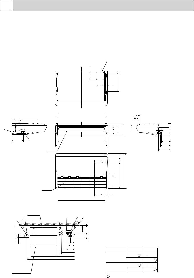
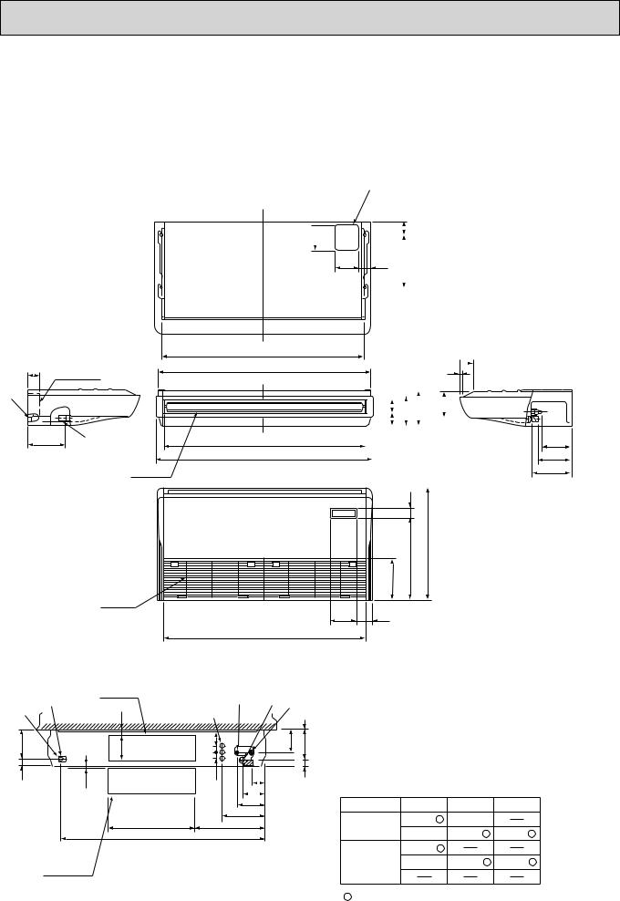
 OUTLINES AND DIMENTIONS
INDOOR UNIT PCA-RP50GA PCA-RP50GA#1 PCH-P50GAH
Unit : mm
NOTES:
1.Use M10 or W3/8 screws for anchor bolt.
2.When optional drain lift-up mechanism is installed, always provide upward piping for refrigerant piping.
|
|
|
17 |
|
|
150 |
|
80 |
140 |
70 |
320 |
|
|
|
|
|
933 (suspension bolt pitch) |
|
|
|
|
|
|
|
85 |
|||
70 |
|
|
|
|
|
|
||||||||||
Electrical box |
|
983 |
|
|||||||||||||
|
|
|
15 |
|
|
|
||||||||||
|
|
|
|
|
|
|
|
|
|
|
|
|
|
|
|
|
|
|
|
|
|
|
|
|
|
|
|
|
|
|
|
||
|
|
|
|
|
|
|
|
|
|
|
|
|
|
|
|
|
|
|
|
|
|
|
|
|
|
|
|
|
|
|
|
|
|
|
|
|
|
|
|
|
|
|
|
|
|
|
|
|
|
|
|
|
210 |
157 |
81 |
180 |
||
76 |
|
|
|
|
|
|
|
|
|
|
|
226 |
|
|
|
904 |
|
|
|
|
|
||
|
|
|
1000 |
|
|
|
|
Air outlet |
|
||
56
680
|
506 |
|
254 |
Air intake |
|
161 |
90 |
918 |
|
182 liquid
201 gas
241 (Drainage)
|
|
|
Electrical box [Front view] |
|
|
|||
|
|
32 |
|
|
|
|||
|
Ceiling |
|
|
|
||||
|
|
|
|
|
|
|||
|
|
|
|
|
|
1 |
||
|
|
|
|
|
|
|
||
|
|
|
|
|
|
|
|
|
179 |
|
|
161 |
|
38 79 |
|
131 |
175 |
42 |
6~7 |
|
|
|
38 |
|
|
46 |
|
|
|
86 |
|
|
|||
|
|
|
|
|
|
|
|
|
|
|
|
|
|
|
138 |
|
|
|
|
|
|
|
|
171 |
|
|
|
|
|
|
525 |
|
263 |
|
|
|
|
|
|
|
352 |
|
|
|
|
|
|
|
928 |
|
|
|
|
When electrical |
|
|
|
|
|
|||
box is pulled |
|
|
|
|
|
|||
down |
|
|
|
|
|
|
|
|
1 Drainage pipe connection (26mm I.D.)
2 Drainage pipe connection (for the left arrangement)
3 Knockout hole for left drain-piping arrangement
4 Refrigerant-pipe connection (gas pipe side/flared connection)
5 Refrigerant-pipe connection (liquid pipe side/flared connection)
6 Knockout hole for upper drain pipe arrangement
7 Knockout hole for left drain pipe arrangement
8 Knockout hole for wiring arrangement
Use the current nuts meeting the pipe size of the outdoor unit.
Available pipe size |
|
|
|
RP50 |
P50 |
LIQUID SIDE |
:6.35 |
|
|
:9.52 |
:9.52 |
GAS SIDE |
:12.7 |
|
|
:15.88 |
:15.88 |
: Initial flare nut size
15
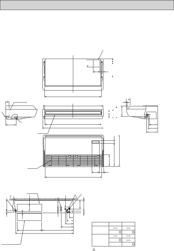
PCA-RP50GA2
PCA-RP50GA2#1
PCA-RP60GA
PCA-RP71GA
PCA-RP60GA#1
PCA-RP71GA#1
PCH-P60GAH
PCH-P71GAH
70
Electrical box
226
Air outlet
Air intake
Unit : mm
NOTES:
1.Use M10 or W3/8 screws for anchor bolt.
2.When optional drain lift-up mechanism is installed, always provide upward piping for refrigerant piping.
150 17
140
1240 (suspension bolt pitch)
1290
1214
1310
161
1228
|
80 |
|
|
|
|
|
|
|
70 |
320 |
|
|
||
|
|
|
|
|
|
|
|
|
85
15 
|
|
|
|
|
|
|
|
157 |
|
||
|
76 |
|
180 |
210 |
|
||||||
|
|
81 |
|
|
|
|
|
|
|||
|
|
|
|
|
|
|
|
|
|||
|
|
|
|
|
|
|
|
|
|
||
|
|
|
|
|
|
|
|
|
|
|
|
|
|
|
|
|
|
|
|
|
|
|
|
|
|
|
|
|
|
|
|
|
|
|
|
|
|
|
|
|
|
|
|
|
|
|
|
56
506 680
254
90
182 (liquid)
201 (5/8F gas)
241 (Drainage)
|
Electrical box |
[ Front view ] |
|
|
|
||
|
|
|
32 |
Ceiling |
|
|
|
|
|
|
|
||
|
|
|
|
1 |
|
|
|
|
|
|
|
179 |
161 |
|
3879 |
131 |
175 |
42 |
6~7 |
|
38 |
86 |
46 |
|
|
|
|
|
|
|
|
|
|
138 |
|
|
|
|
|
171 |
|
|
|
525 |
|
263 |
|
|
|
|
416 |
|
|
|
|
1235 |
|
|
|
|
When electrical |
|
|
|
|
|
box is pulled |
|
|
|
|
|
down |
|
|
|
|
1 Drainage pipe connection (26mm I.D.)
2 Drainage pipe connection (for the left arrangement)
3 Knockout hole for left drain-piping arrangement
4 Refrigerant-pipe connection (gas pipe side/flared connection)
5 Refrigerant-pipe connection (liquid pipe side/flared connection)
6 Knockout hole for upper drain pipe arrangement
7 Knockout hole for left drain pipe arrangement
8 Knockout hole for wiring arrangement
Use the current nuts meeting the pipe size of the outdoor unit.
Available pipe size
|
RP50 |
RP60 |
RP71,P60,P71 |
LIQUID SIDE |
:6.35 |
:6.35 |
|
|
:9.52 |
:9.52 |
:9.52 |
GAS SIDE |
:12.7 |
|
|
|
:15.88 |
:15.88 |
:15.88 |
: Initial flare nut size
16
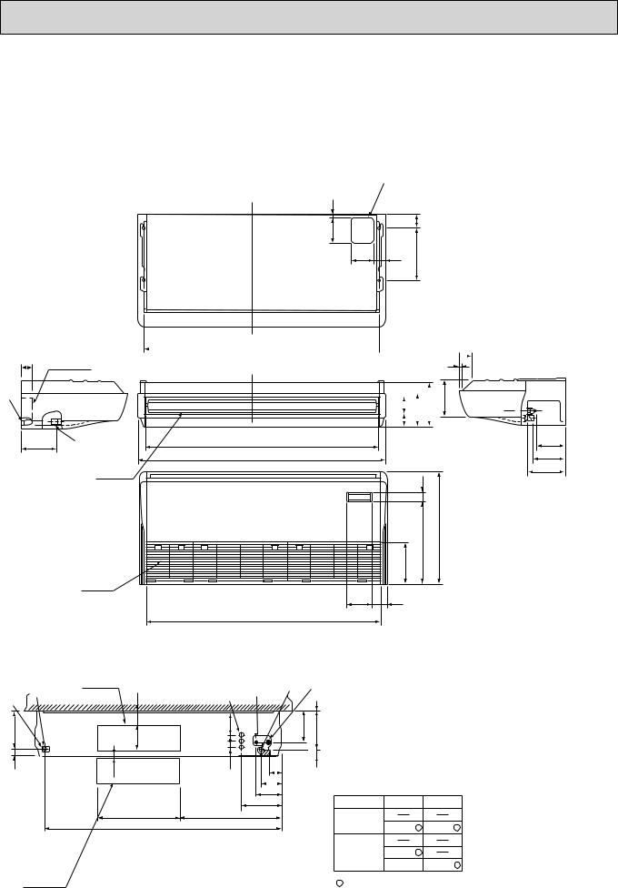
PCA-RP100GA
PCA-RP100GA#1
PCH-P100GAH
70 |
Electrical box |
|


229
Air outlet
Air intake
Unit : mm
NOTES:
1.Use M10 or W3/8 screws for anchor bolt.
2.When optional drain lift-up mechanism is installed, always provide upward piping for refrigerant piping.
150 18
140
1240 (suspension bolt pitch)
1214
1310
161
1228
|
80 |
|
|
|
|
|
|
|
70 |
320 |
|
|
||
|
|
|
|
|
|
|
|
|
87
16 
|
|
|
|
|
|
|
|
|
|
|
217 |
|
|
|
|
|
|
|
|
|
|
||
|
|
|
|
|
|
|
|
270 |
|||
|
96 |
|
207 |
|
|||||||
|
|
|
|||||||||
|
|
|
81 |
|
|
|
|
|
|
||
|
|
|
|
|
|
|
|
|
|
||
|
|
|
|
|
|
|
|
|
|
|
|
|
|
|
|
|
|
|
|
|
|
|
|
|
|
|
|
|
|
|
|
|
|
|
|
56
506 680
254
90
182 (3/8F liquid)
198 (5/8F, 3/4F gas)
245 (Drainage)
|
Electrical box |
[ Front view ] |
|
|
|
|
|
|
|||||
93 |
|
|
|
|||
|
Ceiling |
|
|
1 |
||
|
|
|
|
|
|
|
239 |
160 |
|
38 140 |
|
192 |
236 |
42 |
6~7 |
|
38 |
|
|
45 |
|
|
86 |
|
|
||
|
|
|
|
|
|
|
|
|
|
|
138 |
|
|
|
|
|
|
171 |
|
|
|
525 |
|
|
263 |
|
|
|
|
687 |
|
|
|
|
|
|
1235 |
|
|
|
|
When electrical |
|
|
|
|
|
|
box is pulled |
|
|
|
|
|
|
down |
|
|
|
|
|
|
1 Drainage pipe connection (26mm I.D.)
2 Drainage pipe connection (for the left arrangement)
3 Knockout hole for left drain-piping arrangement
4 Refrigerant-pipe connection (gas pipe side/flared connection)
5 Refrigerant-pipe connection (liquid pipe side/flared connection)
6 Knockout hole for upper drain pipe arrangement
7 Knockout hole for left drain pipe arrangement
8 Knockout hole for wiring arrangement
Use the current nuts meeting the pipe size of the outdoor unit.
Available pipe size
RP100 P100
LIQUID SIDE
:9.52 :9.52
GAS SIDE
:15.88 :19.05 :19.05
:Initial flare nut size
17
PCA-RP125GA PCA-RP140GA PCA-RP125GA#1 PCA-RP140GA#1 PCH-P125GAH PCH-P140GAH
70
Electrical box
229
Air outlet
Air intake
Unit : mm
NOTES:
1.Use M10 or W3/8 screws for anchor bolt.
2.When optional drain lift-up mechanism is installed, always provide upward piping for refrigerant piping.
|
|
|
18 |
|
|
150 |
|
80 |
140 |
70 |
320 |
|
1547(suspension bolt pitch)  87
87
16 
|
|
|
|
|
|
|
217 |
|
|
|
|
|
|
|
270 |
||
|
96 |
|
207 |
|
||||
|
|
|
||||||
|
81 |
|
|
|
|
|
||
|
|
|
|
|
|
|
|
|
1524
1620
56
680
|
506 |
|
254 |
161 |
90 |
1535 |
|
182 (3/8F liquid)
198 (5/8F, 3/4F gas)
245 (Drainage)
|
|
239 |
|
42 |
|
Electrical box |
[ Front view ] |
|
|
93 |
Ceiling |
160 |
|
6~7
525
|
|
|
|
|
|
||
|
|
|
1 |
38 140 |
|
192 |
236 |
38 |
45 |
|
86 |
||
|
||
|
138 |
|
|
171 |
|
|
263 |
|
687 |
|
1545
When electrical box is pulled down
1 Drainage pipe connection (26mm I.D.)
2 Drainage pipe connection (for the left arrangement)
3 Knockout hole for left drain-piping arrangement
4 Refrigerant-pipe connection (gas pipe side/flared connection)
5 Refrigerant-pipe connection (liquid pipe side/flared connection)
6 Knockout hole for upper drain pipe arrangement
7 Knockout hole for left drain pipe arrangement
8 Knockout hole for wiring arrangement
Use the current nuts meeting the pipe size of the outdoor unit.
Available pipe size
RP125,140 P125,140
LIQUID SIDE
:9.52 :9.52
GAS SIDE
:15.88 :19.05 :19.05
:Initial flare nut size
18
 Loading...