


CEILING-CONCEALED (LOW/MEDIUM/HIGH-STATIC PRESSURE)
PEFY-P-NMSU-E/PEFY-P-NMAU-E/PEFY-P-NMHU-E
1. |
SPECIFICATIONS.................................................................................................................................................. |
PEFY-3 |
|
2. |
EXTERNAL DIMENSIONS................................................................................................................................... |
PEFY-12 |
|
3. |
CENTER OF GRAVITY......................................................................................................................................... |
PEFY-17 |
|
4. |
ELECTRICAL WIRING DIAGRAMS..................................................................................................................... |
PEFY-19 |
|
5. |
SOUND PRESSURE LEVELS.............................................................................................................................. |
PEFY-23 |
|
|
5-1. |
Sound Pressure Levels............................................................................................................................... |
PEFY-23 |
|
5-2. |
NC Curves.................................................................................................................................................. |
PEFY-24 |
6. |
FAN CHARACTERISTIC CURVES...................................................................................................................... |
PEFY-34 |
|
7. |
VENTILATION AIR INTAKE/STATIC PRESSURE CURVES................................................................................ |
PEFY-56 |
|
8. |
OPTIONAL PARTS............................................................................................................................................... |
PEFY-57 |
|
|
8-1. Optional Parts Line Up for the Indoor Unit.................................................................................................. |
PEFY-57 |
|
|
8-2. FBL1-Series Filter Boxes for PEFY-P-NMSU-E.......................................................................................... |
PEFY-57 |
|
|
8-3. FBM2-Series Filter Boxes for PEFY-P-NMAU-E......................................................................................... |
PEFY-58 |
|
|
8-4. BRP-Series Bottom Return Plate for PEFY-P-NMAU-E............................................................................. |
PEFY-58 |
|
|
8-5. Long-life Filter PAC-KE-LAF and Filter Box PAC-KE-TB-F for PEFY-P-NMHU-E...................................... |
PEFY-59 |
|
|
8-6. External Heater Adapter CN24RELAY-KIT-CM3 for PEFY-P-NMHU-E/NMAU-E ...................................... |
PEFY-59 |
|
|
8-7. |
External Heater Adapter CN24RELAY-KIT-CM3 for PEFY-P-NMSU-E ..................................................... |
PEFY-60 |
|
8-8. |
Drain Pump Kit PAC-KE04DM-F for PEFY-P-NMHU-E.............................................................................. |
PEFY-60 |
E-NMSU-P-PEFY E-NMAU-P-PEFY E-NMHU-P-PEFY
PEFY-P-NMSU-E/PEFY-P-NMAU-E/PEFY-P-NMHU-E (June 2010) |
PEFY-1 |

PEFY-P-NMSU-E PEFY-P-NMAU-E PEFY-P-NMHU-E
CEILING-CONCEALED (LOW/MEDIUM/HIGH-STATIC PRESSURE)
PEFY-P-NMSU-E (Low Profile)
PEFY-P-NMAU-E (Medium Static)
PEFY-P-NMHU-E (Alt. High Static)
PEFY-P-NMSU-E PEFY-P-NMAU-E
PEFY-P-NMHU-E
Flexible design allows for elegant interior layout
The PEFY models are high-performance, ceiling-concealed indoor units. In fact, if it weren’t for the constantly comfortable environment these units deliver, you would not know they were there. The ducted fan coils are designed to be installed above the ceiling, hidden from public view, and they’re extremely quiet with lowest sound of 22 dBA. The PEFY are extremely easy to access and maintain according to their application. They open on one side so you can easily access the fan or motor for maintenance. They can be easily customized to your cooling and heating needs. The external static pressure settings are adjustable to meet different application conditions such as the use of a high performance filter.
7-7/8" extremely thin body of PEFY-NMSU-E requires less ceiling space
100 mm [3-15/16 in]
10 mm or more 600 mm [23-5/8 in] or more [13/32 in]
or more
 200 [7-7/8]
Service space (viewed from the side) |
Access door |
Ceiling surface |
|
PEFY-P06,08,12,15,18,24NMSU-E Model |
unit: mm(in.) |
|
 Sound Pressure Levels
|
|
Low airflow |
Middle airflow |
High airflow |
|
PEFY-P06NMSU-E |
22 dBA |
24 dBA |
28 dBA |
PEFY-P08NMSU-E |
23 dBA |
26 dBA |
30 dBA |
|
PEFY-P12NMSU-E |
23 dBA |
28 dBA |
35 dBA |
|
PEFY-P15NMSU-E |
28 dBA |
30 dBA |
33 dBA |
|
PEFY-P18NMSU-E |
30 dBA |
34 dBA |
37 dBA |
|
PEFY-P24NMSU-E |
30 dBA |
35 dBA |
40 dBA |
|
* (Details are referred to in the specification sheet.)
The additional external static pressure up to 0.8 in.WG on PEFY-NMHU-E provides flexibility for duct extension, branching, and air outlet configuration.
Long room
L-shaped rooms 
 Room with fixed ceiling fixtures
For PEFY-P-NMHU-E, all the maintenance work
can be done from the side inspection hole.
 PEFY-P-NMSU has a condensate lift of 21-11/16 in., and PEFY-P-NMAU has a condensate lift of 27-9/16 in.
Ceiling concealed |
|
P06 |
P08 |
P12 |
P15 |
P18 |
P24 |
P27 |
P30 |
P36 |
P48 |
P54 |
P72 |
P96 |
Nominal cooling cap.*1 |
BTU/h |
6,000 |
8,000 |
12,000 |
15,000 |
18,000 |
24,000 |
27,000 |
30,000 |
36,000 |
48,000 |
54,000 |
72,000 |
96,000 |
Nominal heating cap.*2 |
BTU/h |
6,700 |
9,000 |
13,500 |
17,000 |
20,000 |
27,000 |
30,000 |
34,000 |
40,000 |
54,000 |
60,000 |
80,000 |
108,000 |
PEFY-P-NMSU-E |
|
|
|
|
|
|
|
|
|
|
|
|
|
|
PEFY-P-NMAU-E |
|
|
|
|
|
|
|
|
|
|
|
|
|
|
PEFY-P-NMHU-E
* Refer to the Nominal conditions *1, *2 in the Specification sheet.
PEFY-2 PEFY-P-NMSU-E/PEFY-P-NMAU-E/PEFY-P-NMHU-E (June 2010)

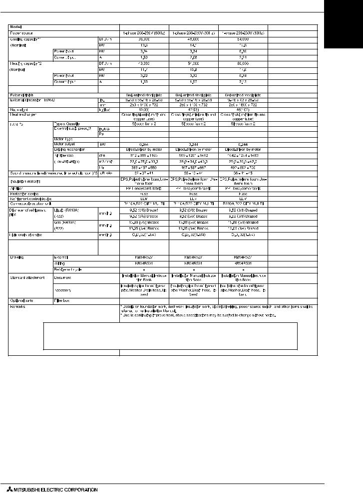
1. SPECIFICATIONS
Model |
|
|
|
PEFY-P06NMSU-E |
PEFY-P08NMSU-E |
|
PEFY-P12NMSU-E |
PEFY-P15NMSU-E |
|
Power source |
|
|
|
|
1-phase 208/230v 60Hz |
|
|
||
Cooling capacity *1 |
|
|
Btu / h |
6,000 |
8,000 |
|
12,000 |
15,000 |
|
(Nominal) |
|
|
kW |
1.8 |
2.3 |
|
3.5 |
4.4 |
|
|
Power input |
kW |
0.05/0.05 |
0.06/0.06 |
|
0.07/0.07 |
0.07/0.07 |
|
|
|
Current input |
A |
0.42/0.41 |
0.51/0.49 |
|
0.56/0.53 |
0.57/0.55 |
|
|
Heating capacity *2 |
|
|
Btu / h |
6,700 |
9,000 |
|
13,500 |
17,000 |
|
(Nominal) |
|
|
kW |
2.0 |
2.6 |
|
4.0 |
5.0 |
|
|
Power input |
kW |
0.03/0.03 |
0.04/0.04 |
|
0.05/0.05 |
0.05/0.05 |
|
|
|
Current input |
A |
0.32/0.31 |
0.41/0.39 |
|
0.46/0.43 |
0.47/0.45 |
|
|
MCA |
|
|
A |
0.47 / 0.50 |
0.47 / 0.50 |
|
0.68 / 0.74 |
1.20 / 1.33 |
|
External finish |
|
|
|
|
Galvanized |
|
|
||
External dimension H x W x D |
in. |
7-7/8 X 31-1/8 X 27-9/16 |
7-7/8 X 31-1/8 X 27-9/16 |
|
7-7/8 X 31-1/8 X 27-9/16 |
7-7/8 X 39 X 27-9/16 |
|||
|
|
|
|
|
|
|
|||
mm |
200 X 790 X 700 |
200 X 790 X 700 |
|
200 X 790 X 700 |
200 X 990 X 700 |
||||
|
|
|
|
||||||
Net weight |
|
|
Lbs (kg) |
42(19) |
42(19) |
|
46(20) |
54(24) |
|
Heat exchanger |
|
|
|
|
Cross fin(aluminium |
fin and copper tube) |
|
|
|
|
Type x quantity |
|
Sirocco fan x 2 |
Sirocco fan x 2 |
|
Sirocco fan x 2 |
SIROCCO FAN X 3 |
||
|
|
|
in.WG |
0.02-(0.06*)-0.14-0.20 |
0.02-(0.06*)-0.14-0.20 |
|
0.02-(0.06*)-0.14-0.20 |
0.02-(0.06*)-0.14-0.20 |
|
|
|
|
(208V) |
(208V) |
|
(208V) |
(208V) |
||
|
|
|
|
|
|||||
|
External |
PA |
5-(15*)-35-50 |
5-(15*)-35-50 |
|
5-(15*)-35-50 |
5-(15*)-35-50 |
|
|
|
Static pressure |
in.WG |
0.02-(0.06*)-0.14-0.20 |
0.02-(0.06*)-0.14-0.20 |
|
0.02-(0.06*)-0.14- |
0.02-(0.06*)-0.14- |
|
|
|
|
|
(230V) |
(230V) |
|
0.20(230V) |
0.20(230V) |
||
|
|
|
|
|
|||||
Fan *4 |
|
|
PA |
5-(15*)-35-50 |
5-(15*)-35-50 |
|
5-(15*)-35-50 |
5-(15*)-35-50 |
|
|
Motor type |
|
|
DC brushless motor |
|
|
|||
|
Motor output |
kW |
0.096 |
0.096 |
|
0.096 |
0.096 |
|
|
|
Driving mechanism |
|
|
Direct- |
driven |
|
|
||
|
Airflow rate |
cfm |
176-212-247 |
194-247-317 |
|
211-282-370 |
282-335-388 |
|
|
|
m3 / min. |
5-6-7 |
5.5-7-9 |
|
6-8-10.5 |
8-9.5-11 |
|
||
|
(Low-Mid-High) |
|
|
|
|
|
|
|
|
|
L / s |
83-100-117 |
91-116-150 |
|
100-133-175 |
133-158-183 |
|
||
|
|
|
|
|
|||||
Sound pressure level |
(Low-Mid-High) |
dB <A> |
22-24-28 (208V) |
23-26-30 (208V) |
|
23-28-35 (208V) |
28-30-33 (208V) |
||
dB<A> |
22-24-28 (230V) |
23-26-30 (230V) |
|
23-28-35 (230V) |
28-30-33 (230V) |
||||
(Measured in anechoic room) *4 |
|
||||||||
dB <A> |
- |
- |
|
- |
- |
|
|||
|
|
|
|
|
|||||
Insulation material |
|
|
|
|
Polystyrene foam,polyethylene |
foam,urethane foam |
|
|
|
Air filter |
|
|
|
|
PP honeycomb fabric (washable) |
|
|
||
Protection Device |
|
|
|
|
Fuse |
|
|
||
Refrigerant Control Device |
|
|
LEV |
|
|
||||
Connectable Outdoor Unit |
|
*3 |
R410A,R22 CITY MULTI |
|
R410A,R22 CITY MULTI |
R410A,R22 CITY MULTI |
|||
|
Liquid (R410A) |
in. (mm) |
1/4 (6.35) Brazed |
1/4 (6.35) Brazed |
|
1/4 (6.35) Brazed |
1/4 (6.35) Brazed |
||
|
|
|
|
|
|
|
|||
Diameter of |
(R22 ) |
1/4 (6.35) Brazed |
1/4 (6.35) Brazed |
|
1/4 (6.35) Brazed |
1/4 (6.35) Brazed |
|||
|
|
||||||||
refrigerant pipe |
|
|
|
|
|
|
|
|
|
Gas |
|
1/2 (12.7) Brazed |
1/2 (12.7) Brazed |
|
1/2 (12.7) Brazed |
1/2 (12.7) Brazed |
|||
(O.D.) |
|
|
|||||||
(R410A) |
in. (mm) |
1/2 (12.7) Brazed |
1/2 (12.7) Brazed |
|
1/2 (12.7) Brazed |
1/2 (12.7) Brazed |
|||
|
|
||||||||
|
(R22 ) |
|
|
||||||
|
|
|
|
|
|
|
|
||
Diameter of drain pipe |
|
|
in. (mm) |
O.D. 1-1/4(32) |
O.D. 1-1/4(32) |
|
O.D. 1-1/4(32) |
O.D. 1-1/4(32) |
|
Drain lift mechanism |
|
|
in. (mm) |
21-11/16 (551) |
21-11/16 (551) |
|
21-11/16 (551) |
21-11/16 (551) |
|
|
External |
|
|
WKB94L522 |
|
|
|||
Drawing |
Wiring |
|
|
WKB94L523 |
|
|
|||
|
Refrigerant cycle |
|
|
|
- |
|
|
|
|
Standard |
Document |
|
|
Installation manual, instruction book |
|
|
|||
Attachment |
Accessory |
|
|
Drain hose (flexible joint) |
|
|
|||
Optional Parts |
External heater adaptor |
CN24RELAY-KIT-CM |
CN24RELAY-KIT-CM |
|
CN24RELAY-KIT-CM |
CN24RELAY-KIT-CM |
|||
|
|
|
|
|
|
|
|
|
|
|
|
|
Ventilation Air: Providing sufficient ventilation air is an important part of every building design. |
||||||
|
|
|
ASHRAE standard 62 provides the minimum ventilation air requirements. Also check local |
||||||
Remark |
|
|
codes. |
|
|
|
|||
|
|
|
|
|
|
|
|
|
|
|
|
|
|
|
|
|
|
|
|
|
Installation |
|
Details on foundation work, duct work, insulation work, electrical wiring, power source switch, and other items shall be |
||||||
|
|
referred to the Installation Manual. |
|
|
|
||||
|
|
|
|
|
|
|
|
||
|
|
|
|
|
|
|
|
|
|
|
|
|
|
|
|
|
|
||
Note: |
|
|
*1 Nominal cooling conditions |
|
*2 Nominal heating conditions |
Unit converter |
|||
Indoor: |
|
|
|
80degF D.B. / 67degF W.B. |
|
70degF D.B. (21.1degC D.B.) |
kcal/h = kW x 860 |
||
|
|
(26.7degC D.B. / 19.4degC W.B.) |
|
BTU/h = kW x 3,412 |
|||||
|
|
|
|
|
|||||
Outdoor: |
|
|
|
95degF D.B. (35degC D.B.) |
|
47degF D.B. / 43degF W.B. |
cfm = m3/min x 35.31 |
||
|
|
|
|
(8.3degC D.B. / 6.1degC W.B.) |
lbs = kg / 0.4536 |
||||
|
|
|
|
|
|
|
|||
|
|
|
|
|
|
|
|
|
|
Pipe length: |
|
|
|
|
25 ft. (7.6 m) |
|
25 ft. (7.6 m) |
*Above specification data is |
|
|
|
|
|
|
|
|
|
subject to rounding variation. |
|
Level difference: |
|
|
|
|
0 ft. (0 m) |
|
0 ft. (0 m) |
||
|
|
|
|
|
|
|
|||
*3 PUHY-THMU,PURY- |
THMU,PUHY-YHMU,PURY-YHMU,PQHY, PQRY, PUHY-HP, PUMY-NHMU, PUHY-T/YHMU, PURY-T/YHMU |
||||||||
*4 The external static pressure is set to 15 Pa (0.06 in. WG) at factory shipment. |
|
|
|||||||
*Due to continuing improvement, above specification may be subject to change without notice. |
|
|
|||||||
E-NMSU-P-PEFY E-NMAU-P-PEFY E-NMHU-P-PEFY
PEFY-P-NMSU-E/PEFY-P-NMAU-E/PEFY-P-NMHU-E (June 2010) |
PEFY-3 |

PEFY-P-NMSU-E PEFY-P-NMAU-E PEFY-P-NMHU-E
1. SPECIFICATIONS
Model |
|
|
PEFY-P18NMSU-E |
|
PEFY-P24NMSU-E |
|||
Power source |
|
|
|
1-phase |
208/230V 60Hz |
|||
Cooling capacity *1 |
|
Btu / h |
18,000 |
|
24,000 |
|
||
(Nominal) |
|
kW |
5.3 |
|
7.0 |
|
||
|
|
|
Power input |
kW |
0.09/0.09 |
|
0.12/0.12 |
|
|
|
|
|
|
||||
|
|
|
Current input |
A |
0.74/0.70 |
|
0.98/0.93 |
|
Heating capacity *2 |
|
Btu / h |
20,000 |
|
27,000 |
|
||
(Nominal) |
|
kW |
5.9 |
|
7.9 |
|
||
|
|
|
Power input |
kW |
0.07/0.07 |
|
0.10/0.10 |
|
|
|
|
|
|
||||
|
|
|
Current input |
A |
0.64/0.60 |
|
0.88/0.83 |
|
MCA |
|
A |
1.20 / 1.33 |
|
1.57 / 1.73 |
|
||
External finish |
|
|
|
Galvanized |
||||
External dimension H x W x D |
in. |
7-7/8 x 39 x 27-9/16 |
|
7-7/8 x 46-7/8 x 27-9/16 |
||||
mm |
200 x 990 x 700 |
|
200 x 1190 x 700 |
|||||
|
|
|
|
|
||||
Net weight |
|
Lbs (kg) |
54(24) |
|
62(28) |
|
||
Heat exchanger |
|
|
Cross fin(Aluminium |
fin and copper tube) |
||||
|
|
|
Type x quantity |
|
Sirocco fan x 3 |
|
Sirocco fan x 4 |
|
|
|
|
|
in.WG |
0.02-(0.06*)-0.14-0.20 (208V) |
|
0.02-(0.06*)-0.14-0.20(208V) |
|
|
|
|
External |
PA |
5-(15*)-35-50 |
|
5-(15*)-35-50 |
|
|
|
|
Static pressure |
in.WG |
0.02-(0.06*)-0.14-0.20 (230V) |
|
0.02-(0.06*)-0.14-0.20(230V) |
|
|
|
|
|
PA |
5-(15*)-35-50 |
|
5-(15*)-35-50 |
|
Fan *3 |
Motor type |
|
|
DC brushless motor |
||||
|
|
|
Motor output |
kW |
0.096 |
|
0.096 |
|
|
|
|
Driving mechanism |
|
|
Direct |
-driven |
|
|
|
|
Airflow rate |
cfm |
353-441-529 |
|
423-565-706 |
|
|
|
|
m3 / min. |
10-12.5-15 |
|
12-16-20 |
|
|
|
|
|
(Low-Mid-High) |
|
|
|
|
|
|
|
|
L / s |
167-208-250 |
|
200-267-333 |
|
|
|
|
|
|
|
|
|||
Sound pressure level |
(Low-Mid-High) |
dB <A> |
30-34-37 (208V) |
|
30-35-40 (208V) |
|||
dB<A> |
30-34-37 (230V) |
|
30-35-40 (230V) |
|||||
(Measured in anechoic room) *3 |
|
|||||||
dB <A> |
- |
|
- |
|
||||
|
|
|
|
|
|
|||
Insulation material |
|
|
Polystyrene foam,Polyethylene foam,Urethane foam |
|||||
Air filter |
|
|
PP Honeycomb fabric (washable) |
|||||
Protection Device |
|
|
|
Fuse |
||||
Refrigerant Control Device |
|
|
LEV |
|||||
Connectable Outdoor Unit |
|
R410A,R22 CITY MULTI |
|
R410A,R22 CITY MULTI |
||||
|
|
|
Liquid (R410A) |
in. (mm) |
1/4 (6.35) Brazed |
|
3/8 (9.52) Brazed |
|
|
|
|
3/8 (9.52) Brazed |
|
3/8 (9.52) Brazed |
|||
Diameter of |
(R22 ) |
|
||||||
|
|
|
|
|
||||
refrigerant pipe |
|
|
|
|
|
|
||
Gas |
|
1/2 (12.7) Brazed |
|
5/8 (15.88) Brazed |
||||
(O.D.) |
|
|
||||||
(R410A) |
in. (mm) |
5/8 (15.88) Brazed |
|
5/8 (15.88) Brazed |
||||
|
|
|
|
|||||
|
|
|
(R22 ) |
|
|
|
|
|
Diameter of drain pipe |
|
in. (mm) |
O.D. 1-1/4(32) |
|
O.D. 1-1/4(32) |
|||
Drain lift mechanism |
|
in. (mm) |
21-11/16 (551) |
|
21-11/16 (551) |
|
||
|
|
|
External |
|
|
WKB94L522 |
||
Drawing |
Wiring |
|
|
WKB94L523 |
||||
|
|
|
Refrigerant cycle |
|
|
- |
|
|
Standard |
Document |
|
Installation Manual, Instruction Book |
|||||
Attachment |
Accessory |
|
|
Drain hose (flexible joint) |
||||
Optional Parts |
External heater adaptor |
CN24RELAY-KIT-CM |
|
CN24RELAY-KIT-CM |
||||
Remark |
|
|
Details on foundation work, duct work, insulation work, electrical wiring, power source switch, and other |
|||||
|
|
|
|
|
items shall be referred to the Installation Manual. |
|||
|
|
|
|
|
|
|
|
|
Ventilation Air: Providing sufficient ventilation air is an important part of every building design.
ASHRAE standard 62 provides the minimum ventilation air requirements. Also check local codes.
Note: |
*1 Nominal cooling conditions |
*2 Nominal heating conditions |
Unit converter |
|
Indoor: |
80degF D.B. / 67degF W.B. |
70degF D.B. (21.1degC D.B.) |
kcal/h = kW x 860 |
|
(26.7degC D.B. / 19.4degC W.B.) |
BTU/h = kW x 3,412 |
|||
|
|
|||
Outdoor: |
95degF D.B. (35degC D.B.) |
47degF D.B. / 43degF W.B. |
cfm = m3/min x 35.31 |
|
(8.3degC D.B. / 6.1degC W.B.) |
lbs = kg / 0.4536 |
|||
|
|
|||
|
|
|
|
|
Pipe length: |
25 ft. (7.6 m) |
25 ft. (7.6 m) |
*Above specification data is |
|
Level difference: |
0 ft. (0 m) |
0 ft. (0 m) |
subject to rounding variation. |
|
|
||||
*3 The external static pressure is set to 15 Pa (0.06 in. WG) at factory shipment. |
|
|||
*Due to continuing improvement, above specification may be subject to change without notice. |
|
|||
PEFY-4 PEFY-P-NMSU-E/PEFY-P-NMAU-E/PEFY-P-NMHU-E (June 2010)

1. SPECIFICATIONS
|
|
PEFY-P06NMAU-E |
PEFY-P08NMAU-E |
PEFY-P12NMAU-E |
PEFY-P15NMAU-E |
MCA |
A |
1.05 |
1.05 |
1.21 |
1.45 |
|
|
0.14-(0.20*)-0.28-0.40-0.60 0.14-(0.20*)-0.28-0.40-0.60 |
0.14-(0.20*)-0.28-0.40-0.60 0.14-(0.20*)-0.28-0.40-0.60 |
||
|
|
35-(50*)-70-100-150 |
35-(50*)-70-100-150 |
35-(50*)-70-100-150 |
35-(50*)-70-100-150 |
|
|
DC brushless motor |
DC brushless motor |
DC brushless motor |
DC brushless motor |
Drain Lift Mechanism |
|
27-9/16 |
27-9/16 |
27-9/16 |
27-9/16 |
External Heater Adapter |
|
CN24RELAY-KIT-CM3 |
CN24RELAY-KIT-CM3 |
CN24RELAY-KIT-CM3 |
CN24RELAY-KIT-CM3 |
Ventilation Air: Providing sufficient ventilation air is an important part of every building design.
ASHRAE standard 62 provides the minimum ventilation air requirements. Also check local codes.
E-NMSU-P-PEFY E-NMAU-P-PEFY E-NMHU-P-PEFY
Note: |
*1 Nominal cooling conditions |
*2 Nominal heating conditions |
Unit converter |
|
Indoor: |
80degF D.B. / 67degF W.B. |
70degF D.B. (21.1degC D.B.) |
kcal/h = kW x 860 |
|
(26.7degC D.B. / 19.4degC W.B.) |
BTU/h = kW x 3,412 |
|||
|
|
|||
Outdoor: |
95degF D.B. (35degC D.B.) |
47degF D.B. / 43degF W.B. |
cfm = m3/min x 35.31 |
|
(8.3degC D.B. / 6.1degC W.B.) |
lbs = kg / 0.4536 |
|||
|
|
|||
|
|
|
|
|
Pipe length: |
25 ft. (7.6 m) |
25 ft. (7.6 m) |
*Above specification data is |
|
Level difference: |
0 ft. (0 m) |
0 ft. (0 m) |
subject to rounding variation. |
|
|
||||
*3 The rated external static |
pressure is set to 50 Pa (0.20 in. WG) at factory shipment. |
|
||
*Due to continuing improvement, above specification may be subject to change without notice. |
|
|||
PEFY-P-NMSU-E/PEFY-P-NMAU-E/PEFY-P-NMHU-E (June 2010) |
PEFY-5 |

PEFY-P-NMSU-E PEFY-P-NMAU-E PEFY-P-NMHU-E
1. SPECIFICATIONS
|
|
PEFY-P18NMAU-E |
PEFY-P24NMAU-E |
PEFY-P27NMAU-E |
PEFY-P30NMAU-E |
MCA |
A |
1.56 |
2.25 |
2.49 |
2.50 |
|
|
0.14-(0.20*)-0.28-0.40-0.60 0.14-(0.20*)-0.28-0.40-0.60 |
0.14-(0.20*)-0.28-0.40-0.60 0.14-(0.20*)-0.28-0.40-0.60 |
||
|
|
35-(50*)-70-100-150 |
35-(50*)-70-100-150 |
35-(50*)-70-100-150 |
35-(50*)-70-100-150 |
|
|
DC brushless motor |
DC brushless motor |
DC brushless motor |
DC brushless motor |
Drain Lift Mechanism |
|
27-9/16 |
27-9/16 |
27-9/16 |
27-9/16 |
External Heater Adapter |
|
CN24RELAY-KIT-CM3 |
CN24RELAY-KIT-CM3 |
CN24RELAY-KIT-CM3 |
CN24RELAY-KIT-CM3 |
Ventilation Air: Providing sufficient ventilation air is an important part of every building design.
ASHRAE standard 62 provides the minimum ventilation air requirements. Also check local codes.
Note: |
*1 Nominal cooling conditions |
*2 Nominal heating conditions |
Unit converter |
|
Indoor: |
80degF D.B. / 67degF W.B. |
70degF D.B. (21.1degC D.B.) |
kcal/h = kW x 860 |
|
(26.7degC D.B. / 19.4degC W.B.) |
BTU/h = kW x 3,412 |
|||
|
|
|||
Outdoor: |
95degF D.B. (35degC D.B.) |
47degF D.B. / 43degF W.B. |
cfm = m3/min x 35.31 |
|
(8.3degC D.B. / 6.1degC W.B.) |
lbs = kg / 0.4536 |
|||
|
|
|||
Pipe length: |
25 ft. (7.6 m) |
25 ft. (7.6 m) |
*Above specification data is |
|
Level difference: |
0 ft. (0 m) |
0 ft. (0 m) |
subject to rounding variation. |
|
|
||||
*3 The rated external static |
pressure is set to 50 Pa (0.20 in. WG) at factory shipment. |
|
||
*Due to continuing improvement, above specification may be subject to change without notice. |
|
|||
PEFY-6 PEFY-P-NMSU-E/PEFY-P-NMAU-E/PEFY-P-NMHU-E (June 2010)
1. SPECIFICATIONS
|
|
PEFY-P36NMAU-E |
PEFY-P48NMAU-E |
PEFY-P54NMAU-E |
MCA |
A |
3.33 |
3.41 |
3.31 |
|
|
0.14-(0.20*)-0.28-0.40-0.60 |
0.14-(0.20*)-0.28-0.40-0.60 0.14-(0.20*)-0.28-0.40-0.60 |
|
|
|
35-(50*)-70-100-150 |
35-(50*)-70-100-150 |
35-(50*)-70-100-150 |
|
|
DC brushless motor |
DC brushless motor |
DC brushless motor |
Drain Lift Mechanism |
in. |
27-9/16 |
27-9/16 |
27-9/16 |
|
|
CN24RELAY-KIT-CM3 |
CN24RELAY-KIT-CM3 |
CN24RELAY-KIT-CM3 |
Ventilation Air: Providing sufficient ventilation air is an important part of every building design.
ASHRAE standard 62 provides the minimum ventilation air requirements. Also check local codes.
E-NMSU-P-PEFY E-NMAU-P-PEFY E-NMHU-P-PEFY
Note: |
*1 Nominal cooling conditions |
*2 Nominal heating conditions |
Unit converter |
|
Indoor: |
80degF D.B. / 67degF W.B. |
70degF D.B. (21.1degC D.B.) |
kcal/h = kW x 860 |
|
(26.7degC D.B. / 19.4degC W.B.) |
BTU/h = kW x 3,412 |
|||
|
|
|||
Outdoor: |
95degF D.B. (35degC D.B.) |
47degF D.B. / 43degF W.B. |
cfm = m3/min x 35.31 |
|
(8.3degC D.B. / 6.1degC W.B.) |
lbs = kg / 0.4536 |
|||
|
|
|||
|
|
|
|
|
Pipe length: |
25 ft. (7.6 m) |
25 ft. (7.6 m) |
*Above specification data is |
|
Level difference: |
0 ft. (0 m) |
0 ft. (0 m) |
subject to rounding variation. |
|
|
||||
*3 The rated external static |
pressure is set to 50 Pa (0.20 in. WG) at factory shipment. |
|
||
*Due to continuing improvement, above specification may be subject to change without notice. |
|
|||
PEFY-P-NMSU-E/PEFY-P-NMAU-E/PEFY-P-NMHU-E (June 2010) |
PEFY-7 |
PEFY-P-NMSU-E PEFY-P-NMAU-E PEFY-P-NMHU-E
1. SPECIFICATIONS
Model |
|
|
|
|
PEFY-P15NMHU-E |
PEFY-P18NMHU-E |
|
PEFY-P24NMHU-E |
PEFY-P27NMHU-E |
||||
Power source |
|
|
|
|
|
1-phase 208/230 V 60Hz |
|
|
|
||||
Cooling capacity *1 |
|
BTU / h |
15,000 |
18,000 |
|
24,000 |
|
27,000 |
|
||||
(Nominal ) |
|
|
|
kW |
4.4 |
5.3 |
|
7.0 |
|
7.9 |
|
||
|
|
|
Power input |
|
kW |
0.188/0.207 |
0.188/0.207 |
|
0.245/0.270 |
|
0.270/0.297 |
||
|
|
|
Current input |
|
A |
0.96/1.06 |
0.96/1.06 |
|
1.25/1.38 |
|
1.37/1.51 |
||
Heating capacity *2 |
|
BTU / h |
17,000 |
20,000 |
|
27,000 |
|
30,000 |
|
||||
(Nominal) |
|
|
|
kW |
5.0 |
5.9 |
|
7.9 |
|
|
8.8 |
|
|
|
|
|
Power input |
|
kW |
|
|
|
|
|
|
|
|
|
|
|
|
0.188/0.207 |
0.188/0.207 |
|
0.245/0.270 |
|
0.270/0.297 |
||||
|
|
|
Current input |
|
A |
0.96/1.06 |
0.96/1.06 |
|
1.25/1.38 |
|
1.37/1.51 |
||
MCA |
|
|
|
A |
1.20 / 1.33 |
1.20 / 1.33 |
|
1.57 / 1.73 |
|
1.72 / 1.89 |
|||
|
|
|
|
|
|
|
|
|
|
|
|
|
|
External finish |
|
|
|
|
|
Galvanized |
|
|
|
||||
|
|
|
|
|
|
|
|
|
|
|
|
|
|
External dimension H x W x D |
|
in. |
14-31/32 x 29-17/32 x 35-7/16 |
14-31/32 x 29-17/32 x 35-7/16 |
|
14-31/32 x 29-17/32 x 35-7/16 |
14-31/32 x 39-3/8 x 35-7/16 |
||||||
|
|
|
|
|
mm |
380 x 750 x 900 |
380 x 750 x 900 |
|
380 x 750 x 900 |
380 x 1,000 x 900 |
|||
|
|
|
|
|
|
|
|
|
|
|
|
|
|
Net weight |
|
|
|
lbs (kg) |
98 (44) |
100 (45) |
|
100 (45) |
|
111 (50) |
|||
|
|
|
|
|
|
|
|
|
|
||||
Heat exchanger |
|
|
|
Cross fin(Aluminium |
fin and copper tube) |
|
|
|
|||||
|
|
|
|
|
|
|
|
|
|
|
|
|
|
FAN |
*3 |
Type x Quantity |
|
Sirocco fan x 1 |
Sirocco fan x 1 |
|
Sirocco fan x 1 |
Sirocco fan x 1 |
|||||
|
|
|
|
|
|
|
|
|
|
|
|
|
|
|
|
|
External- |
(208V) |
in.WG |
(0.201*)-0.642 (208V) |
(0.201*)-0.642 (208V) |
|
(0.201*)-0.642 (208V) |
(0.201*)-0.642 (208V) |
|||
|
|
|
static |
|
|
|
|
|
(50*)-160 |
|
(50*)-160 |
||
|
|
|
|
Pa |
(50*)-160 |
(50*)-160 |
|
|
|||||
|
|
|
pressure |
|
|
|
|||||||
|
|
|
(230V) |
|
|
|
|
|
|
|
|
|
|
|
|
|
|
in.WG |
0.401-(0.602*)-0.803 (230V) |
0.401-(0.602*)-0.803 (230V) |
|
0.401-(0.602*)-0.803 (230V) |
0.401-(0.602*)-0.803 (230V) |
||||
|
|
|
|
|
Pa |
100-(150*)-200 |
100-(150*)-200 |
|
100-(150*)-200 |
|
100-(150*)-200 |
||
|
|
|
Motor type |
|
|
|
1-phase induction motor |
|
|
|
|||
|
|
|
|
|
|
|
|
|
|
|
|
|
|
|
|
|
Motor output |
|
kW |
0.130 |
0.130 |
|
0.180 |
|
0.220 |
|
|
|
|
|
Driving mechanism |
|
|
Direct- |
driven |
|
|
|
|||
|
|
|
|
|
|
|
|
|
|
|
|
|
|
|
|
|
Airflow rate |
|
cfm |
353-494 |
353-494 |
|
477-671 |
|
547-777 |
||
|
|
|
(Low-High) |
|
|
10.0-14.0 |
10.0-14.0 |
|
13.5-19.0 |
|
15.5-22.0 |
||
|
|
|
|
m3 / min |
|
|
|||||||
|
|
|
|
|
|
167-233 |
167-233 |
|
225-317 |
|
258-367 |
||
|
|
|
|
|
L / s |
|
|
||||||
|
|
|
|
|
|
|
|
|
|
|
|
||
Sound pressure level (Low-High) |
*3 |
dB <A> |
25-32 (208V) |
25-32 (208V) |
|
29-36 (208V) |
|
30-38 (208V) |
|||||
(measured in anechoic room) |
|
dB <A> |
34-39 (230V) |
34-39 (230V) |
|
36-41 (230V) |
|
35-41 (230V) |
|||||
|
|
|
|
|
|
- |
- |
|
- |
|
- |
|
|
|
|
|
|
|
dB <A> |
|
|
|
|||||
|
|
|
|
|
|
|
|
|
|
|
|||
Insulation material |
|
|
|
Polystyrene foam,Polyethylene foam,Urethane foam |
|
|
|
||||||
|
|
|
|
|
|
|
|
|
|
|
|||
Air filter |
|
|
|
|
|
Field-supplied; see Optional Parts |
|
|
|
||||
|
|
|
|
|
|
|
|
|
|||||
Protection device |
|
|
|
Fuse |
|
|
|
||||||
|
|
|
|
|
|
|
|
|
|||||
Refrigerant control device |
|
|
|
LEV |
|
|
|
||||||
|
|
|
|
|
|
|
|
|
|||||
Connectable outdoor unit |
|
|
|
R410A,R22 CITY MULTI |
|
|
|
||||||
|
|
|
|
|
|
|
|
|
|
|
|
|
|
Diameter of |
|
Liquid |
(R410A) |
in. (mm) |
1/4 (6.35) Flare |
1/4 (6.35) Flare |
|
3/8 (9.52) Flare |
3/8 (9.52) Flare |
||||
refrigerant pipe |
|
|
(R22 ) |
|
1/4 (6.35) Flare |
3/8 (9.52) Flare |
|
3/8 (9.52) Flare |
3/8 (9.52) Flare |
||||
(O.D.) |
|
Gas |
(R410A) |
in. (mm) |
1/2 (12.7) Flare |
1/2 (12.7) Flare |
|
5/8 (15.88) Flare |
5/8 (15.88) Flare |
||||
|
|
|
|
(R22 ) |
1/2 (12.7) Flare |
5/8 (15.88) Flare |
|
5/8 (15.88) Flare |
5/8 (15.88) Flare |
||||
|
|
|
|
|
|
|
|
|
|
|
|||
Field drain pipe size |
|
in. (mm) |
O.D. 1-1/4 (32) |
O.D. 1-1/4 (32) |
|
O.D. 1-1/4 (32) |
O.D. 1-1/4 (32) |
||||||
|
|
|
|
|
|
|
|
|
|
|
|
|
|
Drawing |
|
External |
|
|
|
W277664 |
|
|
|
||||
|
|
|
|
|
|
|
W660134 |
|
|
|
|||
|
|
|
Wiring |
|
|
|
|
|
|
||||
|
|
|
|
|
|
|
- |
|
|
|
|
||
|
|
|
Refrigerant cycle |
|
|
|
|
|
|
|
|||
|
|
|
|
|
|
|
|
|
|
|
|||
Standard |
|
Document |
|
|
|
Installation Manual,Installation Book |
|
|
|
||||
attachment |
|
Accessory |
|
|
|
Drain hose I.D. 1-1/4inch (32mm)(flexible joint) |
|
|
|
||||
|
|
|
|
|
|
|
|
|
|
|
|
|
|
Optional parts |
|
Drain pump |
|
|
PAC-KE04DM-F |
PAC-KE04DM-F |
|
PAC-KE04DM-F |
PAC-KE04DM-F |
||||
|
|
|
|
|
|
|
|
|
|
|
|||
|
|
|
External heater adaptor |
|
CN24RELAY-KIT-CM3 |
CN24RELAY-KIT-CM3 |
|
CN24RELAY-KIT-CM3 |
CN24RELAY-KIT-CM3 |
||||
|
|
|
Filter box |
|
|
PAC-KE63TB-F |
PAC-KE63TB-F |
|
PAC-KE63TB-F |
PAC-KE80TB-F |
|||
|
|
|
|
|
|
|
|
|
|
|
|
||
|
|
|
Long life filter |
|
|
PAC-KE86LAF |
PAC-KE86LAF |
|
PAC-KE86LAF |
PAC-KE88LAF |
|||
|
|
|
|
|
|
|
|
|
|
|
|
|
|
Remarks |
|
|
|
|
*Details on foundation work, duct |
work, insulation work, electrical |
wiring, power source switch, and other items shall be referred to the |
||||||
|
|
|
|
|
|
Installation Manual. |
|
|
|
|
|
|
|
|
|
|
|
|
|
*Due to continuing improvement, above specification may be subject to change without notice. |
|
|
|
||||
|
|
|
|
|
|
|
|
|
|
|
|
|
|
Ventilation Air: Providing sufficient ventilation air is an important part of every building design.
ASHRAE standard 62 provides the minimum ventilation air requirements. Also check local codes.
Note: |
*1 Nominal cooling conditions |
*2 Nominal heating conditions |
|
Unit converter |
Indoor: |
80degF D.B. / 67degF W.B. |
70degF D.B. (21.1degC D.B.) |
|
kcal/h = kW x 860 |
(26.7degC D.B. / 19.4degC W.B.) |
|
BTU/h = kW x 3,412 |
||
|
|
|
||
Outdoor: |
95degF D.B. (35degC D.B.) |
47degF D.B. / 43degF W.B. |
|
cfm = m3/min x 35.31 |
(8.3degC D.B. / 6.1degC W.B.) |
|
lbs = kg / 0.4536 |
||
|
|
|
||
|
|
|
|
|
Pipe length: |
25 ft. (7.6 m) |
25 ft. (7.6 m) |
|
*Above specification data is |
|
|
|
|
subject to rounding variation. |
Level difference: |
0 ft. (0 m) |
0 ft. (0 m) |
|
|
|
|
|||
*3 The rated external static |
pressure is set to 50 Pa (0.20 in. WG) for |
208V and 150 Pa (0.60) for 230V at factory shipment. |
|
|
*Due to continuing improvement, above specification may be subject to change without notice. |
|
|||
PEFY-8 PEFY-P-NMSU-E/PEFY-P-NMAU-E/PEFY-P-NMHU-E (June 2010)

1. SPECIFICATIONS
Model |
|
|
|
|
|
PEFY-P30NMHU-E |
PEFY-P36NMHU-E |
|
PEFY-P48NMHU-E |
PEFY-P54NMHU-E |
|
Power source |
|
|
|
|
|
|
1-phase 208/230 V 60Hz |
|
|
||
|
|
|
|
|
|
|
|
|
|
||
Cooling capacity *1 |
|
BTU / h |
30,000 |
36,000 |
|
48,000 |
54,000 |
|
|||
(Nominal) |
|
|
|
|
kW |
8.8 |
10.6 |
|
14.1 |
15.8 |
|
|
|
|
Power input |
|
kW |
0.326/0.360 |
0.683/0.754 |
|
0.683/0.754 |
0.695/0.767 |
|
|
|
|
Current input |
|
A |
1.66/1.83 |
3.38/3.73 |
|
3.38/3.73 |
3.43/3.78 |
|
Heating capacity *2 |
|
BTU / h |
34,000 |
40,000 |
|
54,000 |
60,000 |
|
|||
(Nominal) |
|
|
|
|
kW |
10.0 |
11.7 |
|
15.8 |
17.6 |
|
|
|
|
Power input |
|
kW |
0.326/0.360 |
0.683/0.754 |
|
0.683/0.754 |
0.695/0.767 |
|
|
|
|
Current input |
|
A |
1.66/1.83 |
3.38/3.73 |
|
3.38/3.73 |
3.43/3.78 |
|
|
|
|
|
|
|
|
|
|
|
|
|
MCA |
|
|
|
|
A |
2.08 / 2.29 |
4.23 / 4.67 |
|
4.23 / 4.67 |
4.29 / 4.73 |
|
|
|
|
|
|
|
|
|
|
|
|
|
External finish |
|
|
|
|
|
|
Galvanized |
|
|
||
|
|
|
|
|
|
|
|
|
|
||
External dimension H x W x D |
|
in. |
14-31/32 x 39-3/8 x 35-7/16 |
14-31/32 x 47-1/4 x 35-7/16 |
|
14-31/32 x 47-1/4 x 35-7/16 |
14-31/32 x 47-1/4 x 35-7/16 |
||||
|
|
|
|
|
|
380 x 1,000 x 900 |
380 x 1,200 x 900 |
|
380 x 1,200 x 900 |
380 x 1,200 x 900 |
|
|
|
|
|
|
mm |
|
|||||
|
|
|
|
|
|
|
|
|
|
|
|
Net weight |
|
|
|
|
lbs (kg) |
111 (50) |
155 (70) |
|
155 (70) |
155 (70) |
|
|
|
|
|
|
|
|
|
|
|
||
Heat exchanger |
|
|
|
|
Cross fin(Aluminium |
fin and copper tube) |
|
|
|||
|
|
|
|
|
|
|
|
|
|
|
|
FAN |
*3 |
Type x Quantity |
|
Sirocco fan x 1 |
Sirocco fan x 2 |
|
Sirocco fan x 2 |
Sirocco fan x 2 |
|||
|
|
|
|
|
|
|
|
|
|
|
|
|
|
|
External |
(208V) |
in.WG |
(0.201*)-0.642 (208V) |
(0.201*)-0.642 (208V) |
|
(0.201*)-0.642 (208V) |
(0.201*)-0.642 (208V) |
|
|
|
|
static |
|
Pa |
(50*)-160 |
(50*)-160 |
|
(50*)-160 |
(50*)-160 |
|
|
|
|
pressure |
|
|
||||||
|
|
|
|
(230V) |
in.WG |
0.401-(0.602*)-0.803 (230V) |
0.401-(0.602*)-0.803 (230V) |
|
0.401-(0.602*)-0.803 (230V) |
0.401-(0.602*)-0.803 (230V) |
|
|
|
|
|
|
Pa |
100-(150*)-200 |
100-(150*)-200 |
|
100-(150*)-200 |
100-(150*)-200 |
|
|
|
|
Motor type |
|
|
|
1-phase induction motor |
|
|
||
|
|
|
|
|
|
|
|
|
|
|
|
|
|
|
Motor output |
|
kW |
0.230 |
0.400 |
|
0.400 |
0.400 |
|
|
|
|
|
|
|
|
|
|
|
||
|
|
|
Driving mechanism |
|
|
Direct- |
driven |
|
|
||
|
|
|
|
|
|
|
|
|
|
|
|
|
|
|
Airflow rate |
|
cfm |
636-883 |
936-1,342 |
|
936-1,342 |
989-1,412 |
|
|
|
|
(Low-High) |
|
m3 / min |
18.0-25.0 |
26.5-38.0 |
|
26.5-38.0 |
28.0-40.0 |
|
|
|
|
|
|
|
300-417 |
442-633 |
|
442-633 |
467-667 |
|
|
|
|
|
|
L / s |
|
|||||
|
|
|
|
|
|
|
|
|
|
|
|
Sound pressure level (Low-High) |
*3 |
dB <A> |
33-40 (208V) |
31-41 (208V) |
|
31-41 (208V) |
31-41 (208V) |
||||
(measured in anechoic room) |
|
|
38-43 (230V) |
38-44 (230V) |
|
38-44 (230V) |
38-44 (230V) |
||||
|
dB <A> |
|
|||||||||
|
|
|
|
|
|
- |
- |
|
- |
- |
|
|
|
|
|
|
dB <A> |
|
|
||||
|
|
|
|
|
|
|
|
|
|
||
Insulation material |
|
|
|
|
Polystyrene foam,Polyethylene foam,Urethane foam |
|
|
||||
|
|
|
|
|
|
|
|
|
|
||
Air filter |
|
|
|
|
|
|
Field-supplied; see Optional Parts |
|
|
||
|
|
|
|
|
|
|
|
|
|||
Protection device |
|
|
|
|
Fuse |
|
|
||||
|
|
|
|
|
|
|
|
||||
Refrigerant control device |
|
|
|
LEV |
|
|
|||||
Connectable outdoor unit |
|
|
|
R410A,R22 CITY MULTI |
|
|
|||||
|
|
|
|
|
|
|
|
|
|
|
|
Diameter of |
|
|
Liquid |
(R410A) |
in. (mm) |
3/8 (9.52) Flare |
3/8 (9.52) Flare |
|
3/8 (9.52) Flare |
3/8 (9.52) Flare |
|
refrigerant pipe |
|
(R22 ) |
3/8 (9.52) Flare |
3/8 (9.52) Flare |
|
3/8 (9.52) Flare |
3/8 (9.52) Flare |
||||
(O.D.) |
|
|
|
|
|
|
|
|
|
|
|
|
|
Gas |
(R410A) |
in. (mm) |
5/8 (15.88) Flare |
5/8 (15.88) Flare |
|
5/8 (15.88) Flare |
5/8 (15.88) Flare |
||
|
|
|
|
(R22 ) |
5/8 (15.88) Flare |
3/4 (19.05) Flare |
|
3/4 (19.05) Flare |
3/4 (19.05) Flare |
||
|
|
|
|
|
|
|
|
|
|
|
|
Field drain pipe size |
|
in. (mm) |
O.D. 1-1/4 (32) |
O.D. 1-1/4 (32) |
|
O.D. 1-1/4 (32) |
O.D. 1-1/4 (32) |
||||
|
|
|
|
|
|
|
|
|
|
|
|
Drawing |
|
|
External |
|
|
|
W277664 |
|
|
||
|
|
|
|
|
|
|
W660134 |
|
|
||
|
|
|
Wiring |
|
|
|
|
|
|||
|
|
|
|
|
|
|
- |
|
|
||
|
|
|
Refrigerant cycle |
|
|
|
|
|
|||
|
|
|
|
|
|
|
|
|
|
||
Standard |
|
|
Document |
|
|
|
Installation Manual,Installation Book |
|
|
||
attachment |
|
|
Accessory |
|
|
|
Drain hose I.D. 1-1/4inch (32mm)(flexible joint) |
|
|
||
|
|
|
|
|
|
|
|
|
|
|
|
Optional parts |
|
|
Drain pump |
|
|
PAC-KE04DM-F |
PAC-KE04DM-F |
|
PAC-KE04DM-F |
PAC-KE04DM-F |
|
|
|
|
|
|
|
|
|
|
|
|
|
|
|
|
External heater adaptor |
|
CN24RELAY-KIT-CM3 |
CN24RELAY-KIT-CM3 |
|
CN24RELAY-KIT-CM3 |
CN24RELAY-KIT-CM3 |
||
|
|
|
Filter box |
|
|
PAC-KE80TB-F |
PAC-KE140TB-F |
|
PAC-KE140TB-F |
PAC-KE140TB-F |
|
|
|
|
|
|
|
|
|
|
|
|
|
|
|
|
Long life filter |
|
|
PAC-KE88LAF |
PAC-KE89LAF |
|
PAC-KE89LAF |
PAC-KE89LAF |
|
|
|
|
|
|
|
|
|
|
|
|
|
Remarks |
|
|
|
|
|
*Details on foundation work, duct |
work, insulation work, electrical |
wiring, power source switch, and other items shall be referred to the |
|||
|
|
|
|
|
|
Installation Manual. |
|
|
|
|
|
|
|
|
|
|
|
*Due to continuing improvement, above specification may be subject to change without notice. |
|
|
|||
|
|
|
|
|
|
|
|
|
|
|
|
Ventilation Air: Providing sufficient ventilation air is an important part of every building design.
ASHRAE standard 62 provides the minimum ventilation air requirements. Also check local codes.
Note: |
*1 Nominal cooling conditions |
*2 Nominal heating conditions |
|
Unit converter |
Indoor: |
80degF D.B. / 67degF W.B. |
70degF D.B. (21.1degC D.B.) |
|
kcal/h = kW x 860 |
(26.7degC D.B. / 19.4degC W.B.) |
|
BTU/h = kW x 3,412 |
||
|
|
|
||
Outdoor: |
95degF D.B. (35degC D.B.) |
47degF D.B. / 43degF W.B. |
|
cfm = m3/min x 35.31 |
(8.3degC D.B. / 6.1degC W.B.) |
|
lbs = kg / 0.4536 |
||
|
|
|
||
|
|
|
|
|
Pipe length: |
25 ft. (7.6 m) |
25 ft. (7.6 m) |
|
*Above specification data is |
Level difference: |
0 ft. (0 m) |
0 ft. (0 m) |
|
subject to rounding variation. |
|
|
|||
*3 The rated external static |
pressure is set to 50 Pa (0.20 in. WG) for |
208V and 150 Pa (0.60) for 230V at factory shipment. |
|
|
*Due to continuing improvement, above specification may be subject to change without notice. |
|
|||
E-NMSU-P-PEFY E-NMAU-P-PEFY E-NMHU-P-PEFY
PEFY-P-NMSU-E/PEFY-P-NMAU-E/PEFY-P-NMHU-E (June 2010) |
PEFY-9 |

PEFY-P-NMSU-E PEFY-P-NMAU-E PEFY-P-NMHU-E
1. SPECIFICATIONS
Model |
|
|
|
|
PEFY-P72NMHU-E |
PEFY-P96NMHU-E |
|
|
|
|
Power source |
|
|
|
|
|
3-phase 208/230 V 60Hz |
||||
Cooling capacity |
*1 |
|
BTU / h |
72,000 |
96,000 |
|
|
|
||
(Nominal) |
|
|
|
kW |
21.1 |
28.1 |
|
|
|
|
|
|
|
Power input |
|
kW |
1.352/1.495 |
1.690/1.870 |
|
|
|
|
|
|
Current input |
|
A |
4.48/4.94 |
5.69/6.28 |
|
|
|
Heating capacity |
*2 |
|
BTU / h |
80,000 |
108,000 |
|
|
|
||
(Nominal) |
|
|
|
kW |
23.4 |
31.7 |
|
|
|
|
|
|
|
Power input |
|
kW |
1.352/1.495 |
1.690/1.870 |
|
|
|
|
|
|
Current input |
|
A |
4.48/4.94 |
5.69/6.28 |
|
|
|
MCA |
|
|
|
A |
5.60 / 6.18 |
7.12 / 7.85 |
|
|
|
|
|
|
|
|
|
|
|
|
|
|
|
External finish |
|
|
|
|
|
Galvanized |
||||
|
|
|
|
|
|
|
|
|
||
External dimension H x W x D |
|
in. |
18-17/32 x 49-7/32 x 44-1/8 |
18-17/32 x 49-7/32 x 44-1/8 |
|
|
|
|||
|
|
|
|
|
|
470 x 1,250 x 1,120 |
470 x 1,250 x 1,120 |
|
|
|
|
|
|
|
|
mm |
|
|
|
||
|
|
|
|
|
|
|
|
|
|
|
Net weight |
|
|
|
lbs (kg) |
221 (100) |
221 (100) |
|
|
|
|
|
|
|
|
|
|
|
|
|
|
|
Heat exchanger |
|
|
|
|
Cross fin(Aluminium |
fin and copper tube) |
|
|
||
|
|
|
|
|
|
|
|
|
|
|
FAN |
*3 |
Type x Quantity |
|
Sirocco fan x 2 |
Sirocco fan x 2 |
|
|
|
||
|
|
|
|
|
|
|
|
|
|
|
|
|
|
External- |
(208V) |
in.WG |
0.281-(0.642*) (208V) |
0.281-(0.642*) (208V) |
|
|
|
|
|
|
static |
|
Pa |
70-(160*) |
70-(160*) |
|
|
|
|
|
|
pressure |
|
|
|
|
|||
|
|
|
|
(230V) |
in.WG |
0.401-(0.803*) (230V) |
0.401-(0.803*) (230V) |
|
|
|
|
|
|
|
|
|
|
|
|
||
|
|
|
|
|
Pa |
100-(200*) |
100-(200*) |
|
|
|
|
|
|
Motor type |
|
|
|
3-phase induction motor |
|||
|
|
|
|
|
|
|
|
|
|
|
|
|
|
Motor output |
|
kW |
0.650 |
0.850 |
|
|
|
|
|
|
|
|
|
|
|
|
|
|
|
|
|
Driving mechanism |
|
|
Direct- |
driven |
|||
|
|
|
|
|
|
|
|
|
|
|
|
|
|
Airflow rate |
|
cfm |
2,048 |
2,541 |
|
|
|
|
|
|
|
|
m3 / min |
58.0 |
72.0 |
|
|
|
|
|
|
|
|
|
967 |
1,200 |
|
|
|
|
|
|
|
|
L / s |
|
|
|
||
|
|
|
|
|
|
|
|
|
|
|
Sound pressure level |
*3 |
dB <A> |
45 (208V) |
52 (208V) |
|
|
|
|||
(measured in anechoic room) |
|
|
47 (230V) |
54 (230V) |
|
|
|
|||
|
dB <A> |
|
|
|
||||||
|
|
|
|
|
|
- |
- |
|
|
|
|
|
|
|
|
dB <A> |
|
|
|
||
|
|
|
|
|
|
|
|
|
||
Insulation material |
|
|
|
Polystyrene foam,Polyethylene foam,Urethane foam |
||||||
|
|
|
|
|
|
|
|
|
||
Air filter |
|
|
|
|
|
Field-supplied; see Optional Parts |
||||
|
|
|
|
|
|
|
|
|||
Protection device |
|
|
|
|
Fuse |
|||||
|
|
|
|
|
|
|
||||
Refrigerant control device |
|
|
|
LEV |
||||||
|
|
|
|
|
|
|
||||
Connectable outdoor unit |
|
|
|
R410A,R22 CITY MULTI |
||||||
|
|
|
|
|
|
|
|
|
|
|
Diameter of |
|
Liquid |
(R410A) |
in. (mm) |
3/8 (9.52) Brazed |
3/8 (9.52) Brazed |
|
|
|
|
refrigerant pipe |
|
(R22) |
1/2 (12.7) Brazed |
1/2 (12.7) Brazed |
|
|
|
|||
(O.D.) |
|
|
|
|
|
|
|
|
|
|
|
Gas |
(R410A) |
in. (mm) |
3/4 (19.05) Brazed |
7/8 (22.2) Brazed |
|
|
|
||
|
|
|
|
(R22 ) |
1 (25.4) Brazed |
1-1/8 (28.58) Brazed |
|
|
|
|
|
|
|
|
|
|
|
|
|
|
|
Field drain pipe size |
|
in. (mm) |
O.D. 1-1/4 (32) |
O.D. 1-1/4 (32) |
|
|
|
|||
|
|
|
|
|
|
|
|
|
|
|
Drawing |
|
External |
|
|
|
W277665 |
||||
|
|
|
|
|
|
|
W660130 |
|||
|
|
|
Wiring |
|
|
|
||||
|
|
|
|
|
|
- |
|
|
||
|
|
|
Refrigerant cycle |
|
|
|
|
|||
|
|
|
|
|
|
|
|
|
||
Standard |
|
Document |
|
|
|
Installation Manual,Installation Book |
||||
attachment |
|
Accessory |
|
|
|
Drain hose I.D. 1-1/4inch (32mm)(flexible joint) |
||||
|
|
|
|
|
|
|
|
|
|
|
Optional parts |
|
Drain pump |
|
|
PAC-KE04DM-F |
PAC-KE04DM-F |
|
|
|
|
|
|
|
|
|
|
|
|
|
|
|
|
|
|
External heater adaptor |
|
CN24RELAY-KIT-CM3 |
CN24RELAY-KIT-CM3 |
|
|
|
|
|
|
|
Filter box |
|
|
PAC-KE250TB-F |
PAC-KE250TB-F |
|
|
|
|
|
|
|
|
|
|
|
|
|
|
|
|
|
Long life filter |
|
|
PAC-KE85LAF |
PAC-KE85LAF |
|
|
|
|
|
|
|
|
|
|
|
|
|
|
Remarks |
|
|
|
|
*Details on foundation work, duct |
work, insulation work, electrical |
wiring, power source switch, and other items shall be referred to the |
|||
|
|
|
|
|
|
Installation Manual. |
|
|
|
|
|
|
|
|
|
|
*Due to continuing improvement, above specification may be subject to change without notice. |
||||
|
|
|
|
|
|
|
|
|
|
|
Ventilation Air: Providing sufficient ventilation air is an important part of every building design.
ASHRAE standard 62 provides the minimum ventilation air requirements. Also check local codes.
Note: |
*1 Nominal cooling conditions |
*2 Nominal heating conditions |
Unit converter |
|
Indoor: |
80degF D.B. / 67degF W.B. |
70degF D.B. (21.1degC D.B.) |
kcal/h = kW x 860 |
|
(26.7degC D.B. / 19.4degC W.B.) |
BTU/h = kW x 3,412 |
|||
|
|
|||
Outdoor: |
95degF D.B. (35degC D.B.) |
47degF D.B. / 43degF W.B. |
cfm = m3/min x 35.31 |
|
(8.3degC D.B. / 6.1degC W.B.) |
lbs = kg / 0.4536 |
|||
|
|
|||
Pipe length: |
25 ft. (7.6 m) |
25 ft. (7.6 m) |
*Above specification data is |
|
Level difference: |
0 ft. (0 m) |
0 ft. (0 m) |
subject to rounding variation. |
|
|
||||
*3 The rated external static |
pressure is set to 160 Pa (0.642 in. WG) for |
208V and 200 Pa (0.803) for 230V at factory shipment. |
||
*Due to continuing improvement, above specification may be subject to change without notice. |
|
|||
PEFY-10 PEFY-P-NMSU-E/PEFY-P-NMAU-E/PEFY-P-NMHU-E (June 2010)
1. SPECIFICATIONS
Electrical characteristics of Indoor unit |
|
Symbols: MCA : Min.Circuit Amps (=1.25xFLA) FLA : Full Load Amps |
|||||
|
|
|
|
|
IFM :Indoor Fan Motor |
||
Model |
|
Indoor Unit |
|
IFM |
|||
Hz |
Volts |
Voltage range |
MCA(A) |
FLA(A) |
|||
|
|||||||
PEFY-P06NMSU-E |
|
|
|
0.47 / 0.50 |
0.32 |
/ 0.31 |
|
PEFY-P08NMSU-E |
|
|
|
0.47 / 0.50 |
0.41 |
/ 0.39 |
|
PEFY-P12NMSU-E |
60Hz |
208 / 230V |
188 to 253V |
0.68 / 0.74 |
0.46 |
/ 0.43 |
|
PEFY-P15NMSU-E |
1.20 / 1.33 |
0.47 |
/ 0.45 |
||||
|
|
|
|||||
PEFY-P18NMSU-E |
|
|
|
1.20 / 1.33 |
0.64 |
/ 0.60 |
|
PEFY-P24NMSU-E |
|
|
|
1.57 / 1.73 |
0.88 |
/ 0.83 |
|
|
60Hz |
208 / 230V |
198 to 253V |
|
|
|
|
PEFY-P27NMHU-E |
|
|
|
1.72 / 1.89 |
1.37 |
/ 1.51 |
|
PEFY-P30NMHU-E |
|
|
|
2.08 / 2.29 |
1.66 |
/ 1.83 |
|
PEFY-P36NMHU-E |
60Hz |
208 / 230 V |
188 to 253V |
4.23 / 4.67 |
3.38 |
/ 3.73 |
|
PEFY-P48NMHU-E |
4.23 / 4.67 |
3.38 |
/ 3.73 |
||||
|
|
|
|||||
PEFY-P54NMHU-E |
|
|
|
4.29 / 4.73 |
3.43 |
/ 3.78 |
|
PEFY-P72NMHU-E |
|
|
|
5.60 / 6.18 |
4.48 |
/ 4.94 |
|
PEFY-P96NMHU-E |
|
|
|
7.12 / 7.85 |
5.69 |
/ 6.28 |
|
E-NMSU-P-PEFY E-NMAU-P-PEFY E-NMHU-P-PEFY
PEFY-P-NMSU-E/PEFY-P-NMAU-E/PEFY-P-NMHU-E (June 2010) |
PEFY-11 |

PEFY-P-NMSU-E PEFY-P-NMAU-E PEFY-P-NMHU-E
2. EXTERNAL DIMENSIONS
PEFY-P06,08,12,15,18,24NMSU-E |
Ref.: PEFY_NMSU_EXD_USDB_ALL |
|
Unit : mm(in) |
doorAccess
19/32)
-
777 (30
50(1 |
- |
31/32) |
|
G |
|
31/32) |
|
|
|
|
- |
|
Note2 |
|
|
|
50(1 |
||
|
|
|
|
|
37(1-15/32) |
100(3-15/16) 157.5 (6-7/32) |
37(1-15/32) |
|
|
|
20 (13/16) |
12 (1/2) |
|
L-ø2.9(1/8) |
Drain pipe(O.D.ø32(1-1/4)) (Emergency draining) |
Suspension bolt hole 4-14x30(9/16x1-3/16) Slot |
|
||
345 (13-19/32) |
|
|
|
|
159(6-9/32) |
2xE-ø2.9(1/8) |
|||
|
|
(19/32) |
||
|
|
15 |
|
|
|
13/16) |
andserviceforspaceRequiredmaintenance |
doorAccesssurfaceCeiling |
appointedtheatdooraccesstheMake maintenance.serviceforproperlyposition |
||
|
300 |
|
|
|
|
|
|
|
- |
|
|
|
|
|
|
(11 |
|
|
|
|
|
than |
|
|
|
|
|
23/32) |
|
|
|
|
||
450 More |
|
|
|
|||
|
- |
|
|
|
|
|
|
|
(17 |
|
|
|
|
|
|
450 |
- 23/32) |
|
|
|
|
|
(17 |
|
|
|
|
|
50~150 |
- 29/32) |
|
|
|
|
|
|
|
|
|
|
|
(1 |
- 31/32~5 |
|
|
|
(13/16) |
|
|
|
|
|
Morethan20 |
||
|
|
|
|
|
(13/32) |
|
|
|
|
|
|
Morethan10 |
|
|
100(3-15/16) |
100(3-15/16)xJ=K |
|
|
H |
88(3-15/32) |
88(3-15/32) |
|
M |
|
C |
B(Suspensionboltpitch) |
|
|
N |
|
A |
|
Air inlet |
Airoutlet
100(3-15/16) 100(3-15/16)x(E-1)=F D(Duct)
57(2-1/4)
25(1)
filterAir (11-13/16) 7/32)±29/32-5(6±175 length)(Actual 3/32)-ø27(1holeKnockout wiring)(Transmission |
Drain hose (I.D.ø32(1-1/4)) <accessory> |
theforscrewM10Use1.NoteSuspension bolt (field supply). |
|
|
with |
||
spaceservicetheKeep2.for the maintenance at the bottom. forindicateschartThis3.PEFY-P15·18NMSU-E models,whichhas fans.3 E-P06~12NMSU-PEFYmodels have 2 fans. modelE-P24NMSU-PEFYhave 4 fans. .)mm(in |
|||||||
(21 - 21/32) |
|
|
|
|
|
filter(supply |
|
Less than 550 |
|
|
|
|
air the used,remove is |
||
300 than Less |
|
|
|
|
|
|
|
|
|
|
|
|
|
|
4.In case of the inlet duct |
Knockouthole ø27(1-3/32) (Powersource wiring) |
|
|
|
|
|
|
|
12 (1/2) |
|
|
|
|
|
|
|
20 (13/16) |
|
|
|
|
source) |
|
|
(13/32)10 pitch)bolt(Suspension625 5/8)-(24 |
Drain pump 9/16)-(27700 |
21/32)-(26677 Controlbox |
|
|
bed(Transmission)Terminal pipe(O.D.ø32(1Drain -1/4)) |
||
|
|
70 bed(PowerTerminal |
25/32)-(2 21/32)-(10270 |
(Gravitydraining) |
|||
23 (29/32) |
|
|
|
|
|
|
|
(3 - 9/16) |
200(7 - 7/8) |
|
|
|
|
|
|
90 |
170 (6 - 23/32) |
|
|
|
|
|
|
|
102 (4 - 1/32) |
|
|
|
|
|
|
|
48(1-29/32) |
|
|
|
|
Refrigerantpiping 2 Refrigerant piping connectionbrazing(gas) brazing connection(liquid) |
|
(1-15/16) |
Drainpipe(O.D.ø32(1-1/4)) |
|
|
|
|
ø2.9(1/8)- |
|
15/16)-100(349 |
|
23(29/32) 10(13/32) |
|
|
116 |
19/32) - (4 |
|
|
|
|
|
|
(3-15/16) |
|
|
30(1-3/16) |
|
25(1) |
|
|
100 |
|
|
20(13/16) |
23(29/32) |
(5-29/32) |
|
|
|
||
|
|
|
150(Duct) |
|
|
|
|
|
|
|
|
|
|
2x2 |
1 |
the unit), then install the filter(field supply) at suction side. |
*1:R410A outdoor unit |
*2:R22 outdoor unit |
|
|
2 Liquid pipe |
ø6.35(1/4) |
*1 ø6.35(1/4) |
*2 ø9.52(3/8) |
ø9.52(3/8) |
1 Gas pipe |
ø12.7(1/2) |
*1 ø12.7(1/2) |
*2 ø15.88(5/8) |
ø15.88(5/8) |
|
1/8)- |
(39) |
7/8)- |
N |
790 |
1190 |
|
(31 |
990 |
(46 |
|
|
1/16)- |
29/32)- |
25/32)- |
M |
839 |
1039 |
1239 |
(33 |
(40 |
(48 |
|
L |
16 |
20 |
24 |
K |
11/16)- |
9/16)- |
7/16)- |
500 |
700 |
900 |
|
|
(19 |
(27 |
(35 |
J 5 |
7 |
9 |
|
|
(26) |
7/8)- |
3/4)- |
H |
860 |
1060 |
|
660 |
(33 |
(41 |
|
|
1/2)- |
3/8)- |
1/4)- |
G |
800 |
||
(31 |
1000 (39 |
1200 (47 |
|
|
5/8)- |
1/2)- |
3/8)- |
F |
600 |
800 |
|
(23 |
(31 |
1000 (39 |
|
E 7 |
9 |
11 |
|
|
(26) |
7/8)- |
-3/4) |
D |
860 |
||
660 |
(33 |
1060 (41 |
|
|
7/16)- |
5/16)- |
3/16)- |
C |
798 |
998 |
1198 |
(31 |
(39 |
(47 |
|
|
5/8)- |
1/2)- |
3/8)- |
B |
752 |
952 |
|
(29 |
(37 |
1152 (45 |
|
|
9/16)- |
7/16)- |
5/16)- |
A |
700 |
900 |
1100 |
|
(27 |
(35 |
(43 |
Model |
PEFY-P06,08,12NMSU-E |
PEFY-P15NMSU-E PEFY-P18NMSU-E |
PEFY-P24NMSU-E |
PEFY-12 PEFY-P-NMSU-E/PEFY-P-NMAU-E/PEFY-P-NMHU-E (June 2010)

2. EXTERNAL DIMENSIONS
2. EXTERNAL DIMENSIONS
PEFY-P06, 08, 12, 15, 18, 24, 27, 30, 36, 48, 54NMAU-E Unit : mm(in.)
Use M10 screw for the Suspension bolt (field supply). Keep the service space for the maintenance at the bottom. This chart indicates for PEFY-P24·27·30·36·48·54NMAU-E models,which have 2 fans. PEFY-P06·08·12·15·18NMAU-E models have 1 fan. In case of the inlet duct is used,remove the air filter (supply with the unit), then install the filter |
(field supply) at suction side. Ventilation air must be 0°C (32°F) or higher when accepting ventilation into PEFY knockout hole. |
||
1. 2. |
3. |
4. |
5. |
Note |
|
|
|
|
|
|
-5/16) 210 |
|
|
|
(8 |
Ventilation air intake Ø100(3-15/16) knock out hole Note 5 |
3-Ø2.9(1/8) mounting hole |
Suspension bolt hole 4-14x30 (9/16x1-3/16) Slot 18 (3/4) |
|
|
|
(5-3/8) |
|
(6-1/16) |
|
135 |
|
|
120° |
||
153 |
|
||
|
|
|
|
120° |
|
|
|
|
|
15/16) |
|
|
|
Ø125 |
|
|
|
- |
|
378 (14-15/16) |
|
(4 |
|
|
|
Ø2.9(1/8)-2xE |
|
Ø32(1D.-1/4)) draining) |
|
||
|
|
200(7-7/8) |
|
Drain pipe(O. (Emergency |
|
15 (5/8) |
|
|
|
|
|
40(1-5/8)
Unit:mm(in.) Liquid2 pipe |
Ø6.35 (1/4) |
Ø9.52 (3/8) |
G (255/8)- |
(331/2)- |
(413/8)- |
(533/16)- |
(611/16)- |
|
|
|
|
|
15/16) - |
13/16) - |
11/16) - |
1/2) - |
3/8) - |
|
|
|
|
658 |
858 |
1058 |
1358 |
1558 |
|
|
|
F 600 |
800 |
1000 |
1300 |
1500 |
|
1 Gas pipe |
Ø12.7 (1/2) |
Ø15.88 (5/8) |
|
(23 |
(31 |
(39 |
(51 |
(59 |
E 7 |
9 |
11 |
14 |
16 |
||||
Model P06,08,12NMAU-PEFY -E P15,P18NMAU-PEFY -E |
P24,27,30NMAU-PEFY -E P36,48NMAU-PEFY -E P54NMAU-PEFY -E |
C D |
(3111/16)- |
(399/16)- |
(477/16)- |
(591/4)- |
(661/8)- |
|
|
|
|
|
660 |
7/8) - |
3/4) - |
9/16) - |
7/16) - |
|
|
|
|
860 |
1060 |
1360 |
1560 |
|
|
|
|
|
(26) |
(33 |
(41 |
(53 |
(61 |
|
|
|
|
1/2)- |
3/8)- |
1/4)- |
1/16)- |
15/16)- |
|
|
|
|
800 |
1000 |
1200 |
1500 |
1700 |
Air filter |
|
Unit:mm(in.) |
A B |
754 |
954 |
1154 |
1454 |
1654 |
|
(27 |
(35 |
(43 |
(55 |
1600 |
|||
|
|
|
|
(29 |
(37 |
(45 |
(57 |
(65 |
|
|
|
|
9/16)- |
7/16)- |
5/16)- |
1/8)- |
(63) |
|
|
|
|
700 |
900 |
1100 |
1400 |
|
G
C pitch) bolt B(Suspension A Airinlet
Model (7/8) 21
23(15/16)
PEFY-P06,08,12NMAU-E PEFY-P15,P18NMAU-E PEFY-P24,27,30NMAU-E PEFY-P36,48NMAU-E PEFY-P54NMAU-EVent
250(9-7/8) 217(8-9/16)
41(1-5/8)
(Suspension |
732(28-7/8) 700(27-9/16) 3/8)-(9238Drain pipe (7/16)10 (O.D.Ø32(1-1/4)) Drain pump |
pitch) |
|
3/8) - |
|
bolt |
|
643(25 |
|
Control box Terminal block(Transmission) Terminal block(Power source) pipe(O.D.Ø32(1-1/4))(Gravity draining) |
|
-(211/16) |
Drain |
(1/16) |
|
67 |
|
136 |
356 |
3/8)- |
|
(5 |
|
Air outlet |
1/4)-(2 |
32(1-5/16) |
pipingRefrigerant connectionbrazing(liquid) |
Ø2.9(1/8)-2x2 pipingRefrigerant connectionbrazing(gas) |
10(7/16) |
57 |
100(3-15/16) |
|
|
|
100(3-15/16)X(E-1)=F |
30(1-3/16) |
|
|
D(Duct) |
20(13/16) |
|
|
|
2 |
1 |
|
73(2-7/8) |
122(4-13/16) |
33(1-5/16) |
|
58(2-5/16) |
|||
40(1-5/8) |
100(3-15/16) |
||
|
|||
|
23(15/16) |
178(7-1/16)(DUCT) |
|
40(1-5/8) |
|
|
|
100(3-15/16) |
|
|
E-NMSU-P-PEFY E-NMAU-P-PEFY E-NMHU-P-PEFY
PEFY-P-NMSU-E/PEFY-P-NMAU-E/PEFY-P-NMHU-E (June 2010) |
PEFY-13 |

PEFY-P-NMSU-E PEFY-P-NMAU-E PEFY-P-NMHU-E
2. EXTERNAL DIMENSIONS
PEFY-P06, 08, 12, 15, 18, 24, 27, 30, 36, 48, 54NMAU-E
Unit : mm(in.)
(11-13/16) Less than 300
0 0 (2-9/16 -7/16 ) 65 -10 (Actual length)
Lessthan700 (27-9/16)
Drain hose (I.D.Ø32(1-1/4)) <accessory>
doorAccess
5/8) -
(30
777
50 |
(2) |
|
|
H |
|
(2) |
Note2 |
50 |
|
|
(4-7/16)(4-7/16) |
|
11(7/16) |
112 |
112 |
J
K
L
Kx(M-1)=N
|
K |
J |
|
6 (1/4) |
(1/8) |
|
P-Ø2.9 |
|
13/16) |
|
|
||
300- |
|
|
|||
|
|
|
(11 |
|
|
|
than |
|
|
||
|
|
More |
|
|
|
3/4) |
|
|
|
|
|
|
- |
|
|
|
|
|
(17 |
|
|
||
|
450 |
|
|
||
|
|
|
|
|
- 3/4) |
|
|
|
450 |
(17 |
maintenanceandservicefor |
|
|
|
|
|
|
|
250~300 |
- |
13/16) |
|
space |
|
|
|
|
||
|
- 7/8~11 |
|
|
|
|
(9 |
|
|
|
|
Required |
Unit:mm(in.) P |
10 |
N |
|
M |
|
L 300 -13/16) |
|
K 150 15/16) (11 |
|
|
(5- |
J 44 -3/4) |
|
|
(1 |
|
1/2)- |
H |
800 |
(31 |
|
Model |
P06,08,12NMAU-E |
|
PEFY- |
10 |
10 |
12 |
12 |
3/4)- |
990 |
7/16)- |
5/16)- |
780 |
1280 |
1480 |
|
(30 |
(39) |
(50 |
(58 |
4 |
4 |
5 |
5 |
-1/4) |
(13) |
-5/8) |
-5/8) |
(10 |
(12 |
(14 |
|
260 |
330 |
320 |
370 |
-(23/16) |
15/16)-(1 |
-(23/16) |
-(23/16) |
54 |
49 |
54 |
54 |
3/8)- |
1/4)- |
1/16)- |
15/16)- |
1000 |
1200 |
1500 |
1700 |
(39 |
(47 |
(59 |
(66 |
PEFY-P15,P18NMAU-E |
PEFY-P24,27,30NMAU-E |
PEFY-P36,48NMAU-E |
PEFY-P54NMAU-E |
Access door |
appointed position properly for service maintenance. |
L |
20(13/16) 250(9-7/8) |
Ceiling surface |
Make the access door at the |
Maintenance type for air filter |
Side maintenance Under maintenance |
Morethan20(13/16) Morethan10(7/16)
PEFY-14 PEFY-P-NMSU-E/PEFY-P-NMAU-E/PEFY-P-NMHU-E (June 2010)
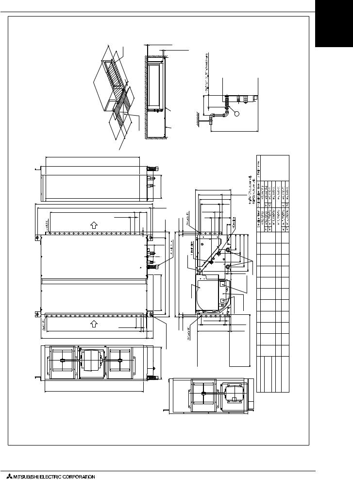
2. EXTERNAL DIMENSIONS
PEFY-P15,18,24,27,30,36,48,54NMHU-E
Note1.Use M10 screw for the Suspension bolt (field supply). 2.Keep the service space for the maintenance from the bottom when the heat exchanger is cleaned. 3.This chart indicates for PEFY-P36·48·54NMHU-E models, which has 2 fans. PEFY-P15·18·24·27·30NMHU-E models have 1 fan. 4.Make sure to install the air filter(field supply) on the air intake side. In case field supplied air filter is used, attach it where the filter service is easily done. 5.On Model :18,36,48,54, you would use flare nut packed with the Indoor Unit, when connecting the Outdoor Unit for R22.
|
|
(24 |
- |
5/8) |
|
Note2 |
|
|
|
|
20(13/16)ormore |
|
|
||||
|
|
|
|
|
|
|
|
|
|
|
|
|
|
||||
|
625 |
|
|
|
|
|
|
|
|
|
|
|
20(13/16)ormore |
||||
maintenance.andserviceforspaceRequired |
|
|
|
|
|
|
|
|
doorAccess |
|
|
|
|
doorAccess |
maintenance.serviceforproperlypositionappointedtheatdooraccesstheMake |
||
|
|
|
|
|
L |
|
|
|
|
|
|
||||||
|
|
|
|
|
|
31/32) |
|
|
|
|
|
|
|
|
|
|
|
|
|
|
|
|
|
|
- |
|
|
|
|
|
|
|
|
|
|
|
|
|
|
|
|
|
(1 |
|
- 31/32) |
|
|
|
|
|
|
|
|
|
|
|
|
|
|
|
50 |
|
|
|
|
|
|
|
|
||
|
|
|
|
|
|
|
|
50 |
(1 |
|
|
|
|
|
|
|
|
|
|
|
|
|
|
|
|
23/32) |
|
|
|
|
|
|
|
|
|
|
|
|
|
|
|
|
|
|
|
|
|
|
|
surfaceCeiling |
|
|
|
|
|
|
|
|
|
|
|
|
- |
|
|
|
|
|
|
|
|
|
|
|
|
|
|
|
|
|
450(17 |
|
|
|
|
|
|
|
|
|
|
|
|
|
150~200- |
|
450 |
- 23/32) |
|
|
|
|
|
|
|
|
|
|
|
|
|
|
9/16) |
|
|
|
|
|
|
|
|
|
|
|
|
|
|
|
|
|
7/8) |
|
|
|
|
|
|
|
|
|
|
|
|
|
|
|
|
|
29/32~7 |
|
(17 |
|
|
|
|
|
|
|
|
|
|
|
|
|
|
|
- |
|
|
|
|
|
|
|
|
|
|
|
|
|
|
|
|
|
(27 |
100~200 |
|
|
|
|
|
|
|
|
|
|
|
|
|
|
|
|
- |
|
|
|
|
|
|
|
|
|
|
|
|
|
|
|
|
|
(5 |
|
|
|
|
|
|
|
|
|
|
|
|
|
|
|
|
|
700 |
|
- 7/8) |
|
|
|
|
|
|
|
|
|
|
|
|
|
|
|
|
- 15/16~7 |
|
|
|
|
|
|
|
|
|
|
|
|
|
|
|
|
|
|
|
|
|
|
|
|
|
|
|
|
|
|
|
|
|
|
|
(3 |
|
|
|
|
|
|
|
|
|
|
|
|
E |
|
|
|
|
|
|
|
|
|
|
|
|
|
|
|
|
|
|
|
|
|
|
|
|
|
|
|
|
250(9-27/32) |
|
|
|
|
|
|
A |
|
|
|
|
|
|
|
|
|
|
|
|
|
|
|
|
B(Suspensionboltpitch) |
|
|
|
(1-31/32) |
23(29/32) |
|
|
|
|
||||||||
50(1-31/32)X(J-1)=K |
|
|
|
|
|
|
50 |
80 |
|
|
|
|
|
|
|||
|
|
|
|
|
50(1-31/32) |
|
(3-5/32) |
|
|
|
|
29(1-5/32) |
|
||||
|
Air outlet |
|
|
|
|
15(19/32) |
|
60(2-3/8) |
|
|
15(19/32) |
||||||
|
|
|
|
|
|
|
|
|
|
|
|
|
|||||
|
|
|
|
|
|
|
|
|
|
|
|
(2-31/32) |
|
|
|
|
|
|
|
|
|
|
|
|
|
|
|
|
|
75) |
( |
|
|
|
|
|
|
|
|
|
|
|
|
|
|
|
|
(2-3/8) |
|
|
|
|
Drain hole (option) |
|
|
|
|
|
|
|
|
|
|
|
|
(60) |
|
|
|
|
|
|
|
|
|
|
|
|
|
|
|
|
|
|
|
904(35-19/32) |
|
|
|
|
|
|
|
|
|
|
|
|
|
|
|
383(15-3/32) |
1/16)(Suspension bolt pitch) |
900(35-7/16) |
847(33-3/8) |
Control box |
|
|
|
|
|
|
|
|
|
|
|
|
|
|
814(32- |
|
|
|
|
|
Air inlet |
|
|
|
|
|
50(1-31/32) |
|
10(13/32) |
|
boltSuspensionhole |
3/16)-14X30(9/16X1- Slot |
|
24(31/32) |
10(13/32) |
||
|
|
|
|
|
|
|
|
|
|
|
|||||||
|
|
|
|
|
|
|
|
|
|
|
|
|
|
|
|||
50(1-31/32)X(G-1)=H |
|
|
|
|
|
|
F |
(1-5/8) |
|
|
|
|
|
||||
|
|
|
|
|
|
|
|
|
|
|
|
41 |
|
|
|
|
|
|
C |
|
|
|
|
|
|
|
|
|
(2-25/32) |
|
|
|
|
|
|
|
|
|
|
|
|
|
|
|
|
|
|
70 |
|
|
|
|
|
|
|
|
|
|
|
|
|
|
|
|
|
|
|
4 |
|
|
|
|
|
|
|
|
|
|
|
|
|
|
|
340(13-13/32) |
|
|
|
|
|
|
D |
|
|
|
|
|
|
|
|
|
|
|
Model:P15~30(Note3) |
|
|
|
|
|
|
|
|
|
|
|
|
|
|
|
|
|
|
|
|
|
|
Drw. : IU-W277664
Unit : mm(in)
300(11-13/16) or less |
|
3 |
|
|
|
installing the drain pump kit (option). |
|
|
|
|
550(21-21/32)Max |
|
|
When |
|
|
|
||
|
|
|
|
|
mm(in.) |
|
Drain hose I.D.32mm (1-1/4inch) <flexible joint> (accessory) |
|
|
380(14-31/32) |
|
|
|
|
|
|
|
|
|
250(9-27/32) |
|
94(3-23/32) |
|
|
|
|
|
|
|
328(12-15/16) |
|
|
|
|
|
|
|
|
|
50X4=200 |
25(1) |
|
|
|
|
|
|
|
|
(1-31/32X4=7-7/8) |
|
|
|
|
|
|
|
|
|
50(1-31/32) |
|
|
|
|
|
|
|
|
|
77 |
130 |
|
|
|
|
|
|
|
|
(3-1/16) |
(5-1/8) |
|
|
|
|
|
|
|
|
|
41 |
|
|
|
|
|
|
|
|
|
5/8) |
|
|
|
|
|
|
|
|
|
(1- |
|
|
|
|
|
23/32)- |
-9/16) |
-7/16) |
|
|
|
|
|
|
|
|||
|
|
163(613/32)- 200(7-7/8) |
|
|
|
L |
780 |
1030 |
1230 |
|
|
|
|
|
450 - |
700 |
900 |
||
|
|
|
343(1317/32)- 387(15-1/4) |
|
K |
23/32)(30 |
9/16)- (40 |
7/16)- (48 |
|
|
|
5/8) |
|
(17 |
(27 |
(35 |
|||
|
|
- 92 |
|
|
|
J |
10 |
15 |
19 |
|
|
(3 |
|
|
|
||||
|
|
|
|
|
hole |
|
11/16) |
1/2)- |
3/8)- |
|
|
30(1-3/16) |
|
Drain |
H |
500 |
800 |
1000 |
|
|
|
|
(19 |
(31 |
(39 |
||||
|
|
|
Terminalbed |
(Transmission) |
F G |
- |
|
|
|
|
|
|
50 31/32) |
25 (1) |
25 (1) |
||||
|
|
|
|
|
|
|
11 |
17 |
21 |
|
|
Terminalbed (Powersource) |
Terminalbox |
|
|
E |
600 |
850 |
1050 |
|
|
|
|
|
|
|
- (1 21/32) |
1/2) - |
3/8) - |
|
|
|
|
|
|
|
550 |
800 |
1000 |
|
|
|
|
|
|
|
- |
-1/2)(31 |
11/32)(39 |
|
|
|
|
ormore. |
D |
-5/8) (21 |
|||
|
|
|
|
25/32)(23 |
5/8)- (33 |
1/2)-(41 |
|||
|
|
|
|
|
|
|
|
|
- |
50(1-31/32) |
|
|
|
in.)15/32- |
C |
(26 |
(36 |
(44 |
|
50X5=250 |
|
45(1-25/32) |
|
|
|
680 |
930 |
1130 |
|
(1-31/32)X5=(9-27/32) |
|
|
|
- |
|
|
|||
340(13-13/32) |
|
17(11/16) |
850mm(33 |
|
(29 |
(39 |
(47 |
||
|
|
|
|
B |
|||||
|
|
|
|
|
|
|
11/16)- |
17/32)- |
13/32)- |
|
|
|
|
work-length |
|
754 |
1004 |
1204 |
|
|
|
|
|
A |
(31 |
(41 |
(49 |
||
|
|
|
|
|
|
|
1/2)- |
11/32)- |
7/32)- |
|
|
|
|
|
|
|
800 |
1050 |
1250 |
|
|
|
|
Keep duct |
Model PEFY-P15NMHU-E |
PEFY-P18NMHU-E |
PEFY-P24NMHU-E PEFY-P27·30NMHU-E |
PEFY-P36·48·54NMHU-E |
|
E-NMSU-P-PEFY E-NMAU-P-PEFY E-NMHU-P-PEFY
PEFY-P-NMSU-E/PEFY-P-NMAU-E/PEFY-P-NMHU-E (June 2010) |
PEFY-15 |

PEFY-P-NMSU-E PEFY-P-NMAU-E PEFY-P-NMHU-E
2. EXTERNAL DIMENSIONS
PEFY-P72,96NMHU-E |
Drw. : IU-W277665 |
|
Unit : mm(in) |
|
|
|
|
|
|
|
|
Note2 |
|
|
|
|
|
20(13/16)ormore |
|
|
|
.supply)(fieldboltSuspensiontheforscrewM10Note1.Use bottomthefrommaintenancetheforspaceservicethe2.Keep cleaned.isexchangerheatthewhen supply)filter(fieldairtheinstalltosure3.Make side.intakeairtheon whereitattachused,isfilterairsuppliedfieldcaseIn done.easilyisservicefilterthe pipeusewouldyoumodel,this4.On connectingwhenUnit,Indoorthewithpacked R22.forUnitOutdoorthe |
|
|
- |
3/4) |
|
|
|
|
|
|
|
|
20(13/16)ormore |
|
|
||
|
|
|
|
|
|
|
|
|
|
|
|
|
|
|
|||
maintenance.andserviceforspaceRequired |
(28 |
|
|
|
|
|
|
|
|
|
|
doorAccess |
surfaceCeilingdoorAccess maintenance.serviceforproperlypositionappointedtheatdooraccesstheMake |
.(option)kitpumpdraintheinstallingWhen |
lessor13/16)-300(11 |
||
|
|
|
|
|
|
|
|
|
|
|
|||||||
|
730 |
|
|
|
|
|
|
|
|
|
|
|
|
|
|
|
|
|
|
|
|
|
5/32) |
|
|
|
|
|
|
|
|
|
|||
|
|
|
|
|
|
|
|
|
|
|
|
|
|
|
|||
|
|
|
|
|
|
|
- |
|
|
|
|
|
|
|
|
|
|
|
|
|
|
|
|
|
|
(53 |
|
|
|
|
|
|
|
|
|
|
|
|
|
|
|
|
|
1350 |
|
|
|
|
|
|
|
|
|
|
|
|
|
|
|
|
|
31/32) |
|
|
|
|
|
|
|
|
|
|
|
|
|
|
|
|
|
|
- |
|
|
|
- 31/32) |
|
|
|
|
|
|
|
|
|
|
|
|
|
(1 |
|
|
|
|
|
|
|
|
|
|
|
|
|
|
|
|
|
50 |
|
|
|
|
|
|
||
|
|
|
|
|
|
|
|
|
|
|
50 |
|
(1 |
|
|
|
|
|
|
|
|
|
|
|
|
|
|
|
|
23/32) |
|
|
|
||
|
|
|
|
|
|
|
|
|
|
|
|
|
|
|
|
||
|
|
|
|
|
|
|
|
|
|
|
|
|
- |
|
|
|
|
|
|
|
|
|
|
|
|
|
|
|
|
450(17 |
|
|
|
||
|
|
|
|
|
|
|
|
|
|
|
|
|
|
|
|
|
3 |
|
|
|
|
|
- |
|
|
|
|
450 |
|
|
23/32) |
|
|
|
|
|
|
|
|
|
150~200 |
|
|
|
|
|
|
|
|
||||
|
|
|
|
|
7/8) |
|
|
|
|
(17 |
- |
|
|
|
|
|
|
|
|
|
|
|
1/2) |
|
|
|
|
|
|
|
|
|
|
||
|
|
|
|
|
29/32~7 |
|
|
|
|
|
|
|
|
|
|||
|
|
|
|
|
- |
|
|
|
|
|
|
|
|
|
|
|
|
|
|
|
|
|
(31 |
- |
|
200~300- |
|
|
|
|
|
|
|
|
|
|
|
|
|
|
|
|
|
|
|
|
|
|
|
|
|
||
|
|
|
|
|
|
(5 |
|
|
|
|
|
|
|
|
|
550(21-21/32)Max |
|
|
|
|
|
|
800 |
|
|
13/16) |
|
|
|
|
|
|
|
||
|
|
|
|
|
|
|
- 7/8~11 |
|
|
|
|
|
|
|
|
||
|
|
|
|
|
|
|
|
|
|
|
|
|
|
|
|
||
|
|
|
|
|
|
|
(7 |
|
|
|
|
|
|
|
|
|
|
1100(43-5/16)
1372(54-1/32) |
|
|
|
1326(52-7/32)(Suspensionboltpitch) |
(1-31/32) |
|
|
|
|
100 |
|
50X20=1000(1-31/32X20=39-3/8) |
|
50 |
|
outlet |
|
|
(3-15/16) |
50(1-31/32) |
|
(19/32) |
|
|
|
|
|
Air |
|
|
15 |
Airinlet |
50(1-31/32) |
10(13/32) |
|
|
|
50X21=1050(1-31/32X21=41-11/32) |
25 |
102 |
|
(1) |
(4-1/32) |
1250(49-7/32) |
|
|
110(43-5/16)
|
340(13-13/32) |
|
|
|
|
|
|
|
|
|
|
|
|
470(18-17/32) |
|
|
|
|
|
|
|
340(13-13/32) |
105 |
|
|
|
|
|
|
|
(4-5/32) |
23(29/32) |
|
|
|
(1-31/32X6=11-13/16) |
20 |
||
|
|
|
|
|
|
50X6=300 |
(13/16) |
|
|
-60(23/8) |
|
29(1-5/32) |
15(19/32) |
327(12-7/8) |
|
|
|
|
44 |
164 |
|||
|
|
|
|
|
|
(1-3/4) |
(6-15/32) |
(3-3/32) |
|
|
|
|
|
||
) |
78 |
( |
|
|
|
|
|
|
|
23/32)(Suspension bolt pitch) |
1124(44-9/32) |
1120(44-1/8) 1067(42-1/32) |
|
Drain hole (option) |
|
|
|
1034(40- |
|
|
|
|
|
|
|
holeboltSuspension |
14X30(9/16X3/16)-4Slot |
|
|
Control box |
|
|
|
24(31/32) |
10(13/32) |
50(1-31/32) |
|||
|
|
|
|
|
|
||
|
|
|
|
|
|
(1-31/32X7=13-25/32) |
|
|
|
|
|
|
|
50X7=350 |
|
|
|
|
|
|
|
420(16-9/16) |
|
|
420(16-9/16) |
|
|
|
|
|
|
41(1-5/8) |
|||
222(8-3/4) 249(9-13/16) |
422(16-5/8) |
489(19-9/32) |
|
(3 |
|
||
3/4)- 95 |
|
|
|
(1-3/16) |
holeDrain |
||
30 |
|
|
|
|
|
|
|
Terminal bed |
(Power source) Terminal bed (Transmission) |
||
|
in.) or more. |
|
35(1-13/32) |
-15/32 |
|
20(13/16) |
||
Keep duct-work length 850mm(33 |
||
|
mm(in.) |
1/4inch) > |
|
(1- joint |
hose |
(accessory) |
Drain I.D.32mm <flexible |
|
Model PEFY-P72NMHU-E |
PEFY-P96NMHU-E |
PEFY-16 PEFY-P-NMSU-E/PEFY-P-NMAU-E/PEFY-P-NMHU-E (June 2010)

3. CENTER OF GRAVITY
PEFY-P06,08,12,15,18,24NMSU-E |
|
|
|
|
|
|
|
|
Ref.: PEFY_NMSU_COG_USDB_ALL |
|||||||||||||||||
|
|
|
|
|
|
W |
|
|
|
|
|
|
|
|
L |
|
|
|
|
|
|
|
|
|||
|
|
|
|
|
|
|
|
|
|
|
|
|
|
|
|
|
|
|
|
|
|
|
|
|
|
|
|
|
|
|
|
|
|
|
|
|
|
|
|
|
|
|
|
|
|
|
|
|
|
|
|
|
|
|
Z |
|
|
X |
|
|
|
|
|
|
|
Y |
A |
|
|
|
|
A: Center of gravity |
|
|
||||||
|
|
|
|
|
|
|
|
|
|
|
|
|
|
|
|
|
|
|
||||||||
|
|
|
|
|
|
|
|
|
|
|
|
|
|
|
|
|
|
|
|
|
||||||
|
|
|
|
|
|
|
|
|
|
|
|
|
|
|
|
|
|
|
|
|
|
|
|
|
||
|
|
|
|
|
|
|
|
|
|
|
|
|
|
|
|
|
|
|
|
|
|
|
|
|
(mm)[in] |
|
|
|
|
|
Model name |
|
W |
|
L |
|
|
|
|
X |
Y |
Z |
|
||||||||||
|
PEFY-P06NMSU-E |
625 [24-5/8] |
|
752 [29-5/8] |
|
263 [10-3/8] |
338 [13-5/16] |
105 [4-5/32] |
|
|||||||||||||||||
|
PEFY-P08NMSU-E |
625 [24-5/8] |
|
752 [29-5/8] |
|
263 [10-3/8] |
338 [13-5/16] |
105 [4-5/32] |
|
|||||||||||||||||
|
PEFY-P12NMSU-E |
625 [24-5/8] |
|
752 [29-5/8] |
|
275 [10-27/32] |
340 [13-13/32] |
104 [4-1/8] |
|
|||||||||||||||||
|
PEFY-P15NMSU-E |
625 [24-5/8] |
|
952 [37-1/2] |
|
280 [11-1/32] |
422 [16-5/8] |
104 [4-1/8] |
|
|||||||||||||||||
|
PEFY-P18NMSU-E |
625 [24-5/8] |
|
952 [37-1/2] |
|
280 [11-1/32] |
422 [16-5/8] |
104 [4-1/8] |
|
|||||||||||||||||
|
PEFY-P24NMSU-E |
625 [24-5/8] |
|
1152 [45-3/8] |
|
285 [11-1/4] |
511 [20-1/8] |
104 [4-1/8] |
|
|||||||||||||||||
PEFY-P15,18,24,27,30,36,48,54,72,96NMHU-E
|
|
|
|
|
|
|
|
W |
|
|
|
|
L |
|
|
|
|
|
|
|
|
|
|
|
|
|
|
|
|
|
|
|
|
|
|
|
|
|
|||
|
|
|
|
|
|
|
|
|
|
|
|
|
|
|
|
|
|
|
|
|
|
|
|
|
|
|
|
|
|
|
|
|
|
|
|
|
|
|
|
|
|
|
|
|
|
|
|
|
|
|
|
|
|
|
|
|
|
|
|
|
|
|
H |
|
|
|
|
|
|
|
|
|
|
|
|
|
|
|
|
|
|
|
|
|
Z |
|
|
|
|
|
|
|
|
|
|
|
|
|
|
|
|
|||
|
|
|
|
|
|
|
|
|
X |
|
|
|
|
|
|
|
|
|
|
|
|
|
|
|
|
|
|
|
|
|
|
|
Y |
|
|
|
A: Center of gravity |
|
|
||
|
|
|
|
|
|
|
|
|
|
|
|
|
|
|
|
|
||||
|
|
|
|
|
|
|
|
|
|
|
|
|
|
|
|
|
||||
|
|
|
|
|
|
|
|
|
|
|
|
|
|
A |
|
(mm)[in] |
||||
|
|
|
|
|
|
|
|
|
|
|
|
|
|
|
|
|
|
|||
|
|
|
|
|
|
|
|
|
|
|
|
|
|
|
|
|
|
|
|
|
|
|
|
|
|
|
|
|
|
|
|
|
|
|
|
||||||
|
|
|
Model name |
|
|
W |
|
L |
|
H |
|
X |
Y |
Z |
||||||
|
|
PEFY-P15NMHU-E |
|
814 |
[32-1/16] |
|
754 [29-11/16] |
210 [8-9/32] |
|
374 [14-3/4] |
440 [17-11/32] |
190 [7-1/2] |
||||||||
|
|
PEFY-P18NMHU-E |
|
814 |
[32-1/16] |
|
754 [29-11/16] |
210 [8-9/32] |
|
374 [14-3/4] |
440 [17-11/32] |
190 [7-1/2] |
||||||||
|
|
PEFY-P24NMHU-E |
|
814 |
[32-1/16] |
|
754 [29-11/16] |
210 [8-9/32] |
|
374 [14-3/4] |
440 [17-11/32] |
190 [7-1/2] |
||||||||
|
|
PEFY-P27NMHU-E |
|
814 |
[32-1/16] |
|
1004 [39-17/32] |
210 [8-9/32] |
|
394 [15-17/32] |
584 [22-32/32] |
190 [7-1/2] |
||||||||
|
|
PEFY-P30NMHU-E |
|
814 |
[32-1/16] |
|
1004 [39-17/32] |
210 [8-9/32] |
|
394 [15-17/32] |
584 [22-32/32] |
190 [7-1/2] |
||||||||
|
|
PEFY-P36NMHU-E |
|
814 |
[32-1/16] |
|
1204 [47-13/32] |
210 [8-9/32] |
|
364 [14-11/32] |
649 [25-9/16] |
190 [7-1/2] |
||||||||
|
|
PEFY-P48NMHU-E |
|
814 |
[32-1/16] |
|
1204 [47-13/32] |
210 [8-9/32] |
|
364 [14-11/32] |
649 [25-9/16] |
190 [7-1/2] |
||||||||
|
|
PEFY-P54NMHU-E |
|
814 |
[32-1/16] |
|
1204 [47-13/32] |
210 [8-9/32] |
|
364 [14-11/32] |
649 [25-9/16] |
190 [7-1/2] |
||||||||
|
|
PEFY-P72NMHU-E |
|
1034 |
[40-23/32] |
|
1326 [52-7/32] |
255 [10-1/16] |
|
462 [18-7/32] |
660 [25-32/32] |
235 [9-9/32] |
||||||||
|
|
PEFY-P96NMHU-E |
|
1034 |
[40-23/32] |
|
1326 [52-7/32] |
255 [10-1/16] |
|
462 [18-7/32] |
660 [25-32/32] |
235 [9-9/32] |
||||||||
E-NMSU-P-PEFY E-NMAU-P-PEFY E-NMHU-P-PEFY
PEFY-P-NMSU-E/PEFY-P-NMAU-E/PEFY-P-NMHU-E (June 2010) |
PEFY-17 |

PEFY-P-NMSU-E PEFY-P-NMAU-E PEFY-P-NMHU-E
3. CENTER OF GRAVITY
PEFY-P06, 08, 12, 15, 18, 24, 27, 30, 36, 48, 54NMAU-E
|
|
|
|
|
|
|
|
W |
|
|
|
|
|
|
|
L |
|
|
|
|
|
|
|
|
|
|
|
||||||
|
|
|
|
|
|
|
|
|
|
|
|
|
|
|
|
|
|
|
|
|
|
|
|
||||||||||
|
|
|
|
|
|
|
|
|
|
|
|
|
|
|
|
|
|
|
|
|
|
|
|
|
|
|
|
|
|
|
|
|
|
|
|
|
|
|
|
|
|
|
|
|
|
|
|
|
|
|
|
|
|
|
|
|
|
|
|
|
|
|
|
|
|
|
|
|
|
|
|
|
|
|
|
|
|
|
|
|
|
|
|
|
|
|
|
|
|
|
|
|
|
|
|
|
|
|
|
|
|
Z |
|
|
|
|
|
|
|
|
|
|
|
|
|
|
|
|
|
|
|
|
|
|
|
|
|
|
|
|
|
|
|
||
|
|
|
|
|
|
|
|
|
|
|
|
|
|
|
|
|
|
|
|
|
|
|
|
|
|
|
|
|
|
|
|
|
|
|
|
|
|
|
|
|
|
|
|
|
|
|
|
|
|
|
|
|
|
|
|
|
|
|
|
|
|
|
|
|
|
|
|
|
|
|
|
|
|
|
|
|
|
|
|
|
|
|
|
|
|
|
|
|
|
|
|
|
|
|
|
|
|
|
|
|
|
|
|
|
|
|
|
|
|
|
|
|
|
|
|
|
|
|
|
|
|
|
|
|
|
|
|
|
|
|
|
|
|
|
|
|
|
|
|
|
|
|
|
|
X |
|
|
|
|
|
|
|
Y |
|
|
A |
|
|
|
|
|
|
A : Center of gravity |
|
|
|
|||
|
|
|
|
|
|
|
|
|
|
|
|
|
|
|
|
|
|
|
|
|
|
|
|
|
|
|
|
|
|
(mm)[in] |
|||
|
|
|
|
|
|
|
|
|
|
|
|
|
|
|
|
|
|
|
|
|
|
|
|
|
|
|
|
|
|
|
|
||
|
|
|
|
|
|
|
|
|
|
|
|
|
|
|
|
|
|
|
|
|
|
|
|
|
|
|
|
|
|
|
|
|
|
|
|
|
|
|
|
|
Model name |
|
|
|
|
W |
|
|
|
L |
|
X |
|
Y |
Z |
||||||||||||
|
|
|
|
PEFY-P06NMAU-E |
643 [25 - 6/16] |
|
754 |
[29 - 11/16] |
330 |
[13] |
300 |
[11 -13/16] |
130 [5 -2/16] |
||||||||||||||||||||
|
|
|
|
PEFY-P08NMAU-E |
643 [25 - 6/16] |
|
754 |
[29 - 11/16] |
330 |
[13] |
300 |
[11 -13/16] |
130 [5 -2/16] |
||||||||||||||||||||
|
|
|
|
PEFY-P12NMAU-E |
643 [25 - 6/16] |
|
754 |
[29 - 11/16] |
330 |
[13] |
300 |
[11 -13/16] |
130 [5 -2/16] |
||||||||||||||||||||
|
|
|
|
PEFY-P15NMAU-E |
643 [25 - 6/16] |
|
954 |
[37 - 9/16] |
340 |
[13 - 7/16] |
375 |
[14 -13/16] |
130 [5 -2/16] |
||||||||||||||||||||
|
|
|
|
PEFY-P18NMAU-E |
643 [25 - 6/16] |
|
954 |
[37 - 9/16] |
340 |
[13 - 7/16] |
375 |
[14 -13/16] |
130 [5 -2/16] |
||||||||||||||||||||
|
|
|
|
PEFY-P24NMAU-E |
643 [25 - 6/16] |
|
1154 [45 - 7/16] |
325 |
[12 - 13/16] |
525 |
[20 -11/16] |
130 [5 -2/16] |
|||||||||||||||||||||
|
|
|
|
PEFY-P27NMAU-E |
643 [25 - 6/16] |
|
1154 [45 - 7/16] |
325 |
[12 - 13/16] |
525 |
[20 -11/16] |
130 [5 -2/16] |
|||||||||||||||||||||
|
|
|
|
PEFY-P30NMAU-E |
643 [25 - 6/16] |
|
1154 [45 - 7/16] |
325 |
[12 - 13/16] |
525 |
[20 -11/16] |
130 [5 -2/16] |
|||||||||||||||||||||
|
|
|
|
PEFY-P36NMAU-E |
643 [25 - 6/16] |
|
1454 [57 - 4/16] |
330 |
[13] |
675 |
[26 -10/16] |
130 [5 -2/16] |
|||||||||||||||||||||
|
|
|
|
PEFY-P48NMAU-E |
643 [25 - 6/16] |
|
1454 [57 - 4/16] |
330 |
[13] |
675 |
[26 -10/16] |
130 [5 -2/16] |
|||||||||||||||||||||
|
|
|
|
PEFY-P54NMAU-E |
643 [25 - 6/16] |
|
1654 [65 - 2/16] |
332 |
[13 - 2/16] |
725 |
[28 -9/16] |
130 [5 -2/16] |
|||||||||||||||||||||
PEFY-18 PEFY-P-NMSU-E/PEFY-P-NMAU-E/PEFY-P-NMHU-E (June 2010)
 Loading...