


WT05000X01
CITY MULTI Control System
and Mitsubishi Mr. SLIM Air Conditioners
MA Remote Controller
PAR-21MAA
Instruction Book
TEMP. |
ON/OFF |
Please read these instructions carefully and take care to use this equipment correctly. Store these instructions safely for future
Be sure to pass these instructions and the corresponding installation instructions to anyone subsequently appointed to maintain this equipment. Installation and
relocation of this equipment should be carried out by qualified persons only. Attempts by end users to install or move this equipment may lead to unsafe conditions or improper operation.
Contents
1. |
Safety Precautions ........................................................................ |
2 |
|
2. |
Parts Names .................................................................................. |
4 |
|
3. |
Screen Configuration ..................................................................... |
6 |
|
4. |
Setting the Day of the Week and Time .......................................... |
6 |
|
5. |
Using the Remote Controller ......................................................... |
7 |
|
|
(1) |
How to Start, Stop, Change the Mode, and Adjust the Temperature .. |
7 |
|
(2) |
Fan Speed, Airflow Direction, and Ventilation ................................ |
9 |
|
(3) |
Using the Timer ............................................................................ |
11 |
|
|
1 Using the Weekly Timer .......................................................... |
11 |
|
|
2 Using the Simple Timer .......................................................... |
13 |
|
|
3 Using the Auto Off Timer ........................................................ |
15 |
|
(4) |
Locking the Remote Controller Buttons |
|
|
|
(Operation function limit controller) .............................................. |
17 |
|
(5) |
Other Indications .......................................................................... |
18 |
6. |
Function Selection ....................................................................... |
20 |
|
7. |
Specifications .............................................................................. |
24 |
|
English
Deutsch
Français
Español
Italiano
Nederlands

1 Safety Precautions
● Precautions are classified as follows, according to the level
 WARNING Denotes a condition or operation which, if handled incorrectly, may lead to serious injury or death.
y lead to bodilyCAUTIONinjury or property damageDenotes. a condition or operation which, if handled
 WARNING
Do not attempt to install this equipment yourself.
Please have your dealer or a qualified engineer install this equipment. Improper installation may result in fire, electric shock, or other severe accident.
Be sure that the equipment has been fastened securely.
Be sure that equipmentequipmentis securely. fastened to a sturdy support so that there is no risk that it will fall.
Be sure that you are supplying the rated voltage.
Supply of an incorrectrequiredvoltage. may lead to fire or equipment
Turnoffthisequipmentimmediatelyifoperationbecomesabnormal.
Continued use may lead to equipment failure, electric shock,
Ifyounoticeaburningsmellorotherabnormality,turnoffthepowerswitch immediately and consult your dealer.
Do not attempt to relocate this equipment yourself.
Improper reinstallation may result in fire, electric shock, or other severe accident.
Please have your dealer or a qualified engineer carry out relocation.
Do not dispose of this equipment yourself.
Please consult the dealer when it comes time to discard this
Do not attempt to modify or repair this equipment yourself.
Attempted modification or repair may lead to fire, electric shock, or other severe accident. Please consult with your dealer if repair is
Stop using this equipment if it fails to operate correctly (if error messages recur and the unit does not run as expected).
Continued use or attempted use of this equipment may lead to fire or equipment failure. Consult your dealer for advice.
– 2 –
 CAUTION
Keep hazardous materials away from this equipment.
Donotinstallthisequipmentfailurein.locationswherethereisriskofcombustible gas leakage. The presence of combustible gas may result in explosion or fire.
Do not wash this equipment with water.
Washing with water may result in electric shock or equipment
Do not touch buttons when hands are wet.
Doing so may result in electric shock or equipment failure.
Donotusethisequipmentforpurposesforwhichitwasnotintended.
This equipment is for use with Mitsubishi Building Air Control systems. Please do not use it with any other systems, or for any other purpose, as such usage may result in improper operation.
Do not spray insect repellant or combustible substances on the equipment.
Keep combustible sprays and substances away from this equipment, and neverspraythemdirectlyontothisequipment.Contactwithorproximityto such substances poses risk of explosion or fire.
Do not use this equipment in improper environments.
Donotuseinareaswheretheremaybelargequantitiesofoil(machineoil, etc.), exhaust gas, or sulfide gas. Such environments may degrade the performance or cause equipment failure.
Do not use sharp-tipped objects to press the buttons.
Use of sharp tips may lead to electric shock or equipment
Do not use under extreme temperatures.
Use only when ambient temperature is within the limits indicated in the instructions. (If the instructions do not indicate limits, use only at temperatures between 0C° and 40 C°.) Use of this equipment at temperatures outside of this range may result in major equipment failure.
Do not pull or twist the communication cables.
Pulling or twisting a cable may result in fire or equipment failure.
Do not disassemble.
Attempteddisassemblymayresultininjuryfromcontactwithinternalparts, or may lead to fire or equipment failure.
Do not wipe this equipment with benzene, paint thinner, or chemical cleaning cloths.
These substances may cause discoloration or equipment failure. If the equipment becomes noticeably dirty, clean it with a wrung-out cloth that has been moistened with water-diluted neutral solvent, and then wipe it with a dry cloth.
– 3 –
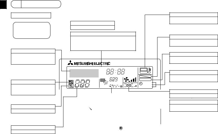
2Parts Names
Display Section
For purposes of this explanation, all parts of the display are shown aslit.Duringactualoperation,only the relevant items will be lit.
Identifies the current operation
Shows the operating mode, etc.
*Multilanguage display is supported.
“CentrallyControlled”indicator
Indicates that operation of the remote controller has been prohibited by a master controller.
“Timer Is Off” indicator
Indicates that the timer is off.
Temperature Setting
Shows the target temperature.
Day-of-Week
Showsthecurrentdayoftheweek.
Time/Timer Display
Showsthecurrenttime,unlessthesimpleorAutoOff timer is set.
If the simple or Auto Off timer is set, shows the time remaining.
TIME SUN MON TUE WED THU FRI SAT
TIMER |
Hr |
ON |
AFTER |
AFTER |
OFF |
|
ERROR CODE |
|
˚F˚C |
˚F˚C |
|
|
|
|
ONLY1Hr. |
|
|
FUNCTION
FILTER
WEEKLY
 SIMPLE AUTO OFF
|
|
|
|
|
|
|
Up/DownAir |
Directionindica- |
|
|
Room Temperature display |
|
|
tor |
|
|
Shows the room temperature. |
|
||
The indicator shows the direc- |
|
|
|
|
|
|
|
|
|
|
|
||
tion of the outcoming airflow. |
|
|
Louver display |
|
||
|
|
|
|
Indicates the action of the swing |
|
|
|
|
|
|
|||
“One Hour Only” indicator |
|
|
louver. Does not appear if the |
|||
Displayed if the airflow is set to |
|
|
louver is stationary. |
|||
weakanddownwardduringCOOL |
|
|
|
|
|
|
|
|
|
|
|
||
or DRY mode. (Operation varies |
|
|
(Power On indicator) |
|
||
according to model.) |
|
|
Indicates that the power is on. |
|
||
The indicator goes off after one |
|
|
|
|
|
|
|
|
|
|
|
||
hour, at which time the airflow di- |
|
|
|
|
|
|
rection also changes. |
|
|
|
|
|
|
|
– 4 – |
|
|
|
||
“Sensor” indication
Displayed when the remote controller sensor is used.
“Locked” indicator
Indicates that remote controller buttons have been locked.
“Clean The Filter” indicator
Comes on when it is time to clean the filter.
Timer indicators
The indicator comes on if the corresponding timer is set.
Fan Speed indicator
Shows the selected fan speed.
Ventilation indicator
Appears when the unit is running in Ventilation mode.

Operation Section
Set Temperature buttons |
|
|
|
Down |
|
|
|
Up |
|
|
|
Timer Menu button |
|
|
|
(Monitor/Setbutton) |
|
|
|
Modebutton(Returnbutton) |
|
|
|
|
|
TEMP. |
|
Set Time buttons |
|
|
|
Back |
|
MENU |
ON/OFF |
Ahead |
BACK |
MONITOR/SET |
DAY |
|
|||
TimerOn/Offbutton |
PAR-21MAA |
CLOCK |
|
(Set Day button) |
|
|
|
Opening the |
|
|
|
door. |
|
|
|
|
|
ON/OFF button |
|
|
|
FanSpeedbutton |
|
|
|
Filter |
button |
|
|
(<Enter>button) |
|
|
ON/OFF |
Test Run button |
|
|
|
|
|
|
|
Check button (Clear button) |
|
|
FILTER |
|
|
|
CHECK |
TEST |
|
OPERATION |
CLEAR |
Airflow Up/Down button |
|
|
|
||
|
|
Louver button |
|
|
|
( |
Operation button) |
|
|
|
To preceding operation |
|
|
|
number. |
Ventilation button
( Operation button) Tonextoperationnumber.
Note:
●If you press a button for a feature that is not installed at the indoor unit, the remote controller will display the “Not Available” message.
If you are using the remote controller to drive multiple indoor units, this message will appear only if the feature is not pres ent at the parent unit.
–5 –
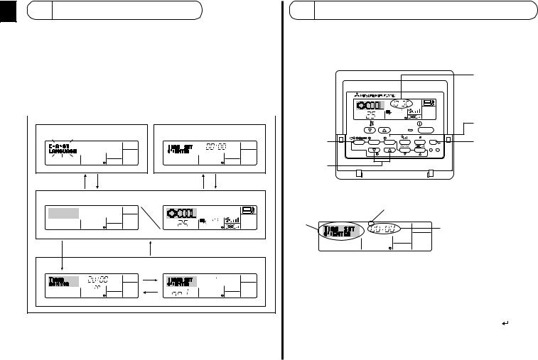
3Screen Configuration
<Screen Types> |
|
time setting. |
|
|
|
|
|||||
● Function Selection of remote controller: |
|
|
|
|
|||||||
|
|
|
|
|
|
|
Set the functions and ranges available to the remote |
||||
|
|
|
|
|
|
|
controller (timer functions, operating restrictions, etc.) |
||||
● Set Day/Time: |
|
Set the current day of the week or time. |
|||||||||
● Standard Control Screens: Viewandsettheairconditioningsystem’soperatingstatus |
|||||||||||
● Timer Monitor: |
|
View the currently set timer (weekly timer, simple timer, |
|||||||||
|
|
|
|
|
|
|
or Auto Off timer) |
|
|
|
|
● Timer Setup: |
|
Set the operation of any of the timers (weekly timer, |
|||||||||
|
|
|
|
|
|
|
simple timer, or Auto Off timer). |
||||
|
|
|
|
||||||||
FunctionSelectionofremotecontroller |
|
Set Day/Time |
|||||||||
|
|
|
|
|
|
|
|
|
|
TIME SUN |
|
|
|
|
|
|
|
|
|
|
|
||
|
|
|
|
|
|
|
|
|
|
|
|
|
|
|
|
|
|
|
|
|
|
|
|
|
|
|
|
|
|
|
|
|
|
|
|
AD C
Standard Control Screens
 °F°C
°F°C
°C
OFF |
ON |
BC
Timer Monitor |
|
Timer Setup |
MON |
|
SUN MON TUE WED THU FRI SAT |
TIMER |
|
|
|
OFF |
°F°C |
B |
WEEKLY |
WEEKLY |
<How to change the screen>
A : Hold down both the Mode button and the Timer On/Off button for 2 seconds. B : Press the Timer Menu button.
C : Press the Mode (Return) button.
D : Press either of the Set Time buttons ( or
or  ).
).
4Setting the Day of theWeek andTime
■Use this screen to change the current day of the week and
Note:
The day and time will not appear if clock use has been disabled at Function Selection of remote controller.
2
A
|
TIME SUN |
|
|
|
|
|
˚C |
|
˚C |
|
|
|
|
|
|
|
|
|
TEMP. |
|
|
ON/OFF |
|
|
MENU |
ON/OFF |
|
FILTER |
|
BACK |
MONITOR/SET |
DAY |
|
CHECK |
TEST |
PAR-21MAA |
CLOCK |
OPERATION |
CLEAR |
|
|
1
Day of the Week & Time display
9
4
<How to Set the Day of the Week and Time...>
3 Day of the Week Setting
2 |
TIME SUN |
4 Time Setting |
|
||
|
|
1.Press the  or
or  Set Time button A to show display 2.
2.Press the Timer On/Off (Set Day) button 9 to set the day.
* Each press advances the day shown at 3 : Sun → Mon → ... → Fri → Sat.
3.Press the appropriate Set Time button A as necessary to set the time.
* As you hold the button down, the time (at 4) will increment first in minute intervals, then in ten-minute intervals, and then in one-hour intervals.
4. After making the appropriate settings at Steps 2 and 3, press the Filter to lock in the values.
– 6 –
Note:
YournewentriesatSteps2and3willbecancelledifyoupresstheMode(Return)button 2 before pressing the Filter button 4.
5. PresstheMode(Return)button 2tocompletethesettingprocedure.Thiswillreturn the display to the standard control screen, where 1will now show the newly set day and time.
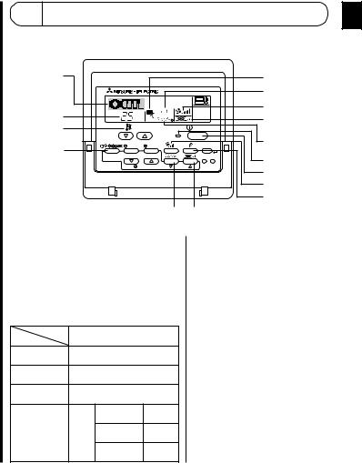
5Using the Remote Controller
(1)How to Start, Stop, Change the Mode, and Adjust the Temperature
2 |
|
|
|
|
|
6 |
|
|
|
|
|
|
4 |
3 |
˚C |
|
˚C |
|
|
5 |
|
|
|
|
8 |
||
|
|
|
|
|
||
3 |
TEMP. |
|
|
ON/OFF |
|
|
|
|
|
|
|||
2 |
MENU |
ON/OFF |
|
FILTER |
7 |
|
|
|
|||||
|
|
|
|
|
|
|
BACK |
MONITOR/SET |
DAY |
|
CHECK |
TEST |
1 |
PAR-21MAA |
CLOCK |
OPERATION |
CLEAR |
|
||
|
1 |
|||||
|
|
|
|
|
|
|
|
|
|
|
|
|
5 |
|
|
|
|
|
|
6 |
|
|
|
7 8 |
|
|
|
<To Start Operation> |
|
|
|
<To Stop Operation> |
||
■ Press the ON/OFF button 1. |
■ PresstheON/OFFbutton 1again. |
• The ON lamp 1 and the display area |
• TheONlamp 1andthedisplay |
come on. |
area go dark. |
Note:
●When the unit is restarted, initial settings are as follows.
|
Remote Controller settings |
|||
Mode |
|
Last operation mode |
||
Temperature |
Last set temperature |
|||
setting |
||||
|
|
|
||
Fan speed |
|
Last set fan speed |
||
|
|
COOL or DRY |
Horiz. |
|
|
|
outlet |
||
|
|
|
||
Airflow up/ |
Mode |
HEAT |
Last |
|
down |
setting |
|||
|
|
|||
|
|
FAN |
Horiz. |
|
|
|
outlet |
||
|
|
|
||
– 7 – |
|
|
|
|

|
<Selecting the Mode> |
|
|
|
|
|
|
<Room Temperature Display> |
||
|
|
|
|
|
|
|
||||
|
■ With the unit running, press the Mode button 2 as many times as necessary. |
During operation, the intake temperature is shown at 4. |
||||||||
|
• Each press switches operation to the next mode, in the sequence shown below. |
Note: |
|
|||||||
|
|
|||||||||
|
|
The currently selected mode is shown at 2. |
|
|
|
|
|
|||
|
|
|
|
|
|
● To display range is 8 °C to 39 °C. If the temperature is below 8 °C or above 39 °C, |
||||
|
|
|
|
|
|
|
|
|
||
|
|
→ COOL → DRY → FAN → AUTO→ → HEAT |
Ventilate |
|
|
|
the corresponding value (8 °C or 39 °C) will blink on the display. |
|||
|
|
|
|
|
● If you are using the remote controller to drive multiple indoor units, the display will |
|||||
|
|
|
|
|
||||||
|
|
*1 |
*1,*3,*4 |
*1 |
*1,*2 |
|
|
|
||
|
|
|
|
show the temperature at the master unit. |
||||||
|
|
|
|
|
|
|
|
|
||
|
Note: |
|
|
|
|
|
|
● Youcanselectwhichtemperaturesensortousetodetectthetemperature:eitherthe |
||
|
|
|
|
|
|
|
sensor at the indoor unit (“At Unit”), or else the sensor at the remote controller (“At |
|||
|
*1 Availability of this mode depends on the type of unit connected. |
Remote”). The default setting is “At Unit”. |
||||||||
|
*2 Appears only on Mr. Slim units with installed ventilation functionality. |
To change the location of the sensor at the indoor unit: |
||||||||
|
*3 DoesnotappearifAutoModehasbeendisabledattheFunctionSelectionofremote |
• CITY MULTI models: |
Consult your dealer. |
|||||||
|
controller. For information about how to set this function, refer to section 6, item [4]– |
• Mr. Slim models: |
Refer to the installation instructions. |
|||||||
2 (2). |
|
|
|
|
|
|
● IfroomtemperaturedisplayisdisabledinFunctionSelectionofremotecontroller,the |
|||
|
*4 HEAT and COOL do not appear during AUTO mode if Auto mode display has been |
roomtemperaturewillnotappear.Forinformationabouthowtoenableordisablethis |
||||||||
|
disabledattheFunctionSelectionofremotecontroller.Forinformationabouthowto |
feature, refer to section 6, item [4]–4 (2). |
||||||||
|
set this function, refer to section 6, item [4]–4 (3). |
|
|
|
|
● IfFahrenheitdisplayisselectedatFunctionSelectionofremotecontroller,thedisplay |
||||
|
<To Change the Room Temperature Setting...> |
|
|
|
|
will show the °F mark. For information about how to select °C or °F, refer to section |
||||
|
|
|
|
|
6, item [4]–4 (1). |
|
||||
■To lower the temperature: Press the  Set Temperature button 3.
■To raise the temperature: Press the  Set Temperature button 3.
• |
Each3 press changes the setting by 1 °C. The current setting is displayed at . |
• |
The available ranges are as follows. *1, *2 |
COOL or DRY |
HEAT mode |
AUTO mode |
FAN |
|
mode |
||||
|
|
|
||
19 - 30C° |
17 - 28C° |
19 - 28C° |
Cannot be set. |
|
(67 - 87F)° *3 |
(63 - 83F)° *3 |
(67 - 83F)° *3 |
||
|
||||
|
|
|
|
Note:
*1 Availablerangesvaryaccordingtothetypeofunitconnected(Mr.Slim,CITYMULTI, etc.).
*2 If temperature range limits have been set at Function Selection of remote controller, theavailablerangeswillbenarrowerthanshownabove.Ifyouattempttosetavalue outside of the restricted range, the display will show a message indicating that the range is currently restricted.
For information about how to set and clear these range limits, refer to section 6, item [4]–2 (3).
*3 If Function Selection of remote controller are set to display the temperature in Fahrenheit.Forinformationabouthowtoselect °Cor °F,refertosection6,item[4]–
4 (1).
– 8 –
 Loading...