


 Loading...
Mitsubishi Electric Building Air-conditioner Control System
Central Controller
G-50A/GB-50A Operation Manual for Initial Setting Web
Contents |
|
|
1 |
Introduction ......................................................................... |
1 |
|
1-1 Conventions Used in This Manual........................................... |
1 |
|
1-2 Computer Requirements ......................................................... |
1 |
|
1-3 Notes on using G-50A with the integrated centralized control |
|
|
software (TG-2000A)................................................................ |
1 |
2 |
Setting the Operating Environment...................................... |
2 |
|
2-1 Setting the PC IP Address....................................................... |
2 |
|
2-2 Setting the Web Browser......................................................... |
4 |
3 |
Performing Operations ........................................................ |
6 |
|
3-1 Entering the User Name and the Password, and Connecting to |
|
|
the G-50A ................................................................................. |
6 |
4 |
Initial Settings...................................................................... |
7 |
|
4-1 Setting the Current Date and Time.......................................... |
7 |
|
4-2 Setting the Basic Information and External Input Functions ... |
8 |
|
4-3 Group Setting ........................................................................ |
14 |
|
4-4 Interlocked Setting................................................................. |
16 |
|
4-5 Block Setting.......................................................................... |
17 |
5 |
Functions 1........................................................................ |
18 |
|
5-1 Error mail reports/E-mail communication .............................. |
18 |
|
5-2 Energy-Save Control and Peak Cut Control ......................... |
21 |
|
5-3 Settings for measurement ..................................................... |
26 |
6 |
Functions 2........................................................................ |
30 |
|
6-1 Limiting the Set Temperature Operating Range ................... |
30 |
|
6-2 Night Mode Schedule ............................................................ |
31 |
|
6-3 Auto-Changeover of Y series ................................................ |
32 |
7 |
User Setting ...................................................................... |
33 |
8 |
Registering a License for Optional Function ...................... |
35 |
Before using the web browser to set the G-50A controller, please read this operation Manual carefully to ensure correct operation.
Store this operation manual in a location that is easy to find.
1 Introduction
A special feature of Mitsubishi Electric Corporation’s “Central Controller G-50A” and "Central Controller GB-50A" are that a PC connected to a LAN can be used to monitor the operation condition of air conditioners, perform air conditioner operations, and make initial settings.
This document explains the procedures for making initial settings for the Central Controller G-50A using the web browser.
Hereinafter, the central controller G-50A and GB-50A, unless otherwise specified, will be called "G-50A".
Note: As GB-50A is not equipped with a LCD for settings, the initial setting must be made on the Initial Setting Web.
1-1 Conventions Used in This Manual
-“Click” refers to the action of positioning the mouse cursor on the object (such as button or folder) and pressing down and releasing the left mouse button once.
-Unless otherwise specified, the example screen images used in this manual are Windows XP® and Internet Explorer 6.0 screen images.
Note: Windows is a registered trademark or trademark of Microsoft Corporation USA in the United States and other countries.
-The K transmission converter (PAC-SC25KAA) and OA processing unit (LOSSNAY) are not included in systems shipped to North America (USA & Canada).
1-2 Computer Requirements
In order to monitor and operate air conditioners by web browser, your computer must meet the following requirements.
|
Table 1-1 Computer Requirements |
|
Item |
|
Requirement |
CPU |
|
Pentium 133MHz or faster (300MHz or faster recommended) |
Memory |
|
64M Bytes or more (128M Bytes or more recommended) |
Screen resolution |
|
1024 x 768 or higher recommended |
|
|
Microsoft® Internet Explorer 5.0 or later |
|
|
Note: You must have a Java execution environment |
|
|
(Microsoft VM Ver5.0 or later or Sun Microsystems Java |
Compatible browser |
|
Plug-in Ver.1.4.2 or later). |
|
Note: You can check the Microsoft VM version by entering “jview” in a |
|
|
|
|
|
|
command prompt. |
|
|
Note: You can check the Sun Microsystems Java Plug-in version in |
|
|
“Java Plug-in” in a control panel. |
On-board LAN port or LAN card |
|
One connector (10BASE-T) |
Other |
|
Pointing device such as a mouse |
Note: Microsoft is a registered trademark or trademark of Microsoft Corporation USA in the United States and other countries.
1-3 Notes on using G-50A with the integrated centralized control software (TG-2000A)
If the system is connected to the integrated centralized control software (referred to as TG-2000A hereafter), make all settings and changes from the TG-2000A so that the data in TG-2000A and G-50A will match.
1
2 Setting the Operating Environment
Given below is an explanation of the PC settings and web browser settings that are required for using a web browser to monitor air conditioner units and perform operations.
2-1 Setting the PC IP Address
You need to set an IP address on the PC that will enable you to connect to the G-50A using a web browser. For instance, if the G-50A IP address is [192.168.1.1], the PC IP address will need to belong to the same system (for example [192.168.1.101]).
If the G-50A is connected to an existing LAN, ask the LAN administrator to decide what PC IP address to use.
Note: When using a G-50A dedicated LAN, we recommend the G-50A main unit be given an IP address within the range [192.168.1.1] — [192.168.1.40] and the PCs that will be connected to the G-50A be given an IP address within the range [192.168.1.101] — [192.168.1.150]
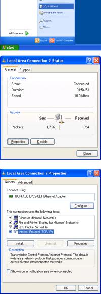
(1)Click on [Control Panel] under [Start] to open the Control Panel.
(2)In the Control Panel window, double click [Network and Dial-up Connections] and the Network and Dial-up Connections window will open. Double click on [Local Area Setting] and the [Local Area Connection Status] dialog will open. Click [Properties].
(3) In the [Local Area Connection Properties] dialog, click [Internet Protocol] to select it and click the [Properties] button.
2

(4) In the [Internet Protocol (TCP/IP) Properties] dialog, click [Use the following IP address] and enter the IP address (for example, “192.168.1.101”) that you want to set in the IP address field.
You normally set [255.255.255.0] as the subnet mask.
Note: Ask your LAN administrator to provide the IP addresses and subnet mask.
(5)Click the [OK] button to close this dialog, and then close the other open dialogs to complete the network setting.
3
2-2 Setting the Web Browser
Perform the necessary web browser settings to enable the web browser to connect to the G-50A.
Note: The settings and screen images used as examples in this manual are based on Internet Explorer 6.0.
2-2-1 Not connecting to the Internet
If the PC you use for monitoring air conditioners and performing operations is not going to be connected to the Internet, use the procedure given below to set the web browser environment settings.
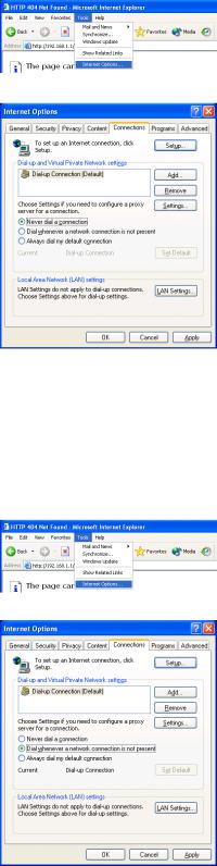
(1)Click the web browser menu item [Tools] and then click [Internet Options…] to select that option.
(2)In the [Internet Options] tabbed dialog, click the [Connections] tab to display that page.
(3)Select [Never dial a connection] in the Dial-up settings section and click the [OK] button to close the dialog.
2-2-2 Connecting to the Internet using a dial-up connection
If the PC you use for monitoring air conditioners and performing operations is going to connect to the Internet via a dial-up connection, use the procedure given below to set the web browser environment settings.
By performing these settings, a message will appear asking whether or not to use a dial-up connection when an Internet connection is necessary. In the case when you want to connect to the Internet, connect to the Internet by following the directions of this message.
(1)Click the web browser menu item [Tools] and then click [Internet Options…] to select that option.
(2)In the [Internet Options] tabbed dialog, click the [Connections] tab to display that page.
(3)Select [Dial whenever a network connection is not present] in the Dial-up settings section and click the [OK] button to close the dialog.
4
2-2-3 Connecting to the Internet using a proxy server (Using an existing LAN)
If the PC you use for monitoring air conditioners and performing operations is going to access the Internet via proxy server by connecting to an existing LAN such as a LAN within your company, use the procedure given below to set the web browser environment settings.
By performing these settings, your PC will connect to a proxy server only when connecting to the Internet.
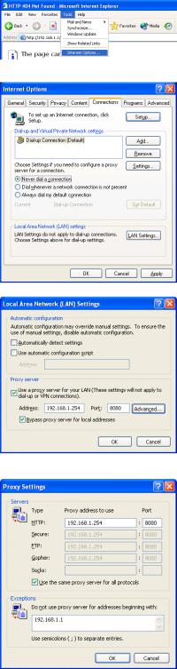
(1)Click the web browser menu item [Tools] and then click [Internet Options…] to select that option.
(2)In the [Internet Options] tabbed dialog, click the [Connections] tab to display that page.
(3)Select [Never dial a connection] in the Dial-up setting section.
(4)Click the [LAN Setting . . .] button in the Local Area Network (LAN) settings section to display the Local Area Network (LAN) Settings dialog.
(5)In the Local Area Network (LAN) Settings dialog, check [Bypass proxy server for local addresses] and click the [Advanced...] button.
(6) Enter the IP address for the G-50A (e.g. 192.168.1.1) in the Exceptions field of the Proxy Setting dialog and click the [OK] button to close the dialog and then close the other open dialogs to complete the setting.
Note: If connecting to more than one G-50A, you can specify multiple IP addresses like [192.168.1.1; 192.168.1.2], however, it is also possible to use the asterisk
(*) and specify [192.168.1*].
5
3 Performing Operations
Given below is an explanation of how to connect to the G-50A and how to make various settings for the G-50A.
Note: If the G-50A is restarted due to circumstances like a power interruption, wait until the screen on the G-50A main unit displays the normal operation screen (it takes several minutes before the normal operation screen is displayed) before using a web browser to access the G-50A. If access is attempted while the G-50A is still starting up, the most recent data might not be displayed or communication errors could occur.
Note: Default IP address of G-50A (GB-50A) is "192.168.1.1". (Factory setting)
3-1 Entering the User Name and the Password, and Connecting to the G-50A
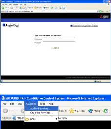
(1) Enter the web page address in the address field of the web browser as follows and press the [Enter] key on the keyboard. A screen appears for login.
http:// [IP address of the G-50A]/g-50/ administrator.html
Note: For example, type “http://192.168.1.1/g-50/administrator.html” if the
G-50A IP address is [192.168.1.1].
(2)To make it easier to connect the next time, click the web browser menu item [Favorites] and click [Add to Favorites] to select that option and add the address to your Favorites folder. Once this address is added to your Favorites folder, it is not necessary to input the address of (1).
You can simply select it from your Favorites folder and the G-50A page will appear.
(3)Enter the user name and the password in the login screen, and click the [Login] button. A screen will appear in which various setting are made. Procedures for making proper settings on each screen will be explained in the following pages.
The table below shows the default user names and passwords for maintenance users and building managers as well as available functions.
User |
Default |
Default |
|
Available functions |
|
user name |
password |
|
|||
|
|
|
|||
|
|
|
Initial settings |
Date and Time, Basic System, Groups, Interlocked |
|
|
|
|
LOSSNAY, Blocks |
||
Maintenance |
initial |
init |
|
|
|
Functions 1 |
E-Mail, Peak cut, Measurement |
||||
user |
|||||
|
|
|
|
||
|
|
|
Functions 2 |
Set Temperature Range Limit, Night Mode |
|
|
|
|
Schedule, Auto-changeover |
||
|
|
|
|
||
|
|
|
|
|
|
Building |
administrator |
admin |
Out of the functions listed above, the items to which access rights have been |
||
manager |
given on the user settings screen are available. |
||||
|
|
||||
Note: The user name and the password for building manager are the same as those of the building manager of the Web for monitoring/operation.
Note: Maintenance users can make available to the administrator only the information necessary for normal operations (group name setting etc.)
Note: It is recommended to change the user name and password not to allow users other than the building manager to change the settings.
Note: The Web page is displayed in the same language as the computer uses and it is also possible to display the Web page in other languages by entering the following Web page addresses.
English |
:Http://[The IP address for G-50A]/g-50/en/administrator.html |
German |
:Http://[The IP address for G-50A]/g-50/de/administrator.html |
French |
:Http://[The IP address for G-50A]/g-50/fr/administrator.html |
Spanish |
:Http://[The IP address for G-50A]/g-50/es/administrator.html |
Italian |
:Http://[The IP address for G-50A]/g-50/it/administrator.html |
Russian |
:Http://[The IP address for G-50A]/g-50/ru/administrator.html |
Chinese |
:Http://[The IP address for G-50A]/g-50/zh/administrator.html |
Japanese |
:Http://[The IP address for G-50A]/g-50/ja/administrator.html |
6
4 Initial Settings
4-1 Setting the Current Date and Time
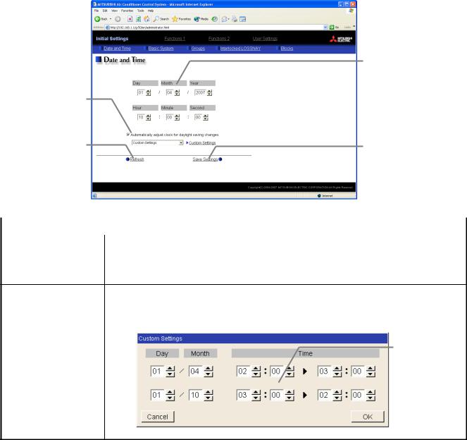
Click [Initial Settings] in the menu, and [Date and Time] screen will appear on the screen. Enter the current date and time, and then press the [Save Settings] button to send the current date and time to G-50A.
Note: If the user logs in as a building manager, the operations may be prohibited.
Note: If the system is connected to the TG-2000A, make all settings and changes from the TG-2000A so that the data in TG-2000A and G-50A will match.
Note: When the time setting is made on this screen, the setting will be applied to all the units on M-NET system.
Note: When the DIDO controller (PAC-YG66DCA), AI Controller (PAC-YG63MCA), or PI Controller (PAC-YG60MCA) is newly connected, make the time setting of the connected controller on this screen.
Summer time setting
Click to set the daylight saving time.
Refresh
Acquires the current Date and Time from G-50A.
Current date/time
Enter the current date and time here.
Save settings
Click to set the current date and time.
Item |
Description |
|
|
|
|
Current date/time |
Enter the current date and time. |
|
For the date, use the format [day - month - year]. |
||
|
||
Save Settings |
Click the [Date/Time Set] button to set the current date and time. |
|
|
|
|
Refresh |
Acquires the current Date and Time from G-50A. |
|
Click and tick the "Automatically adjust clock for daylight saving changes" box to |
|
adjust the daylight saving time automatically, and select your own country. |
|
Note: If your own country is not in the selection bar, select "Custom Settings". Click "Custom Settings" |
|
button that will appear on the right to set the daylight saving time. |
|
Daylight saving |
Summer time setting |
date and time |
|
Set the daylight |
|
saving time. |
Custom Setting Screen
7
4-2 Setting the Basic Information and External Input Functions
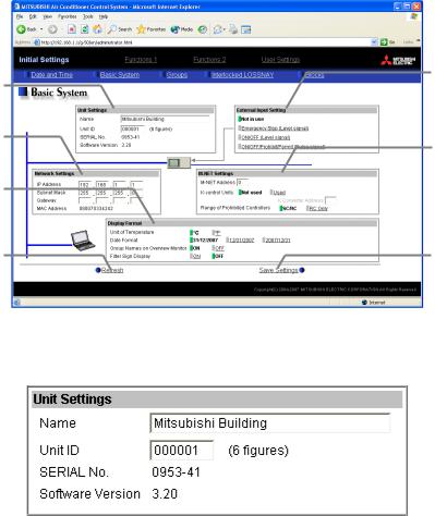
Display the page needed to perform the G-50A basic setting by clicking [Initial Settings]-[Basic System] in the setting menu pane. On this page, you perform the basic setting such as the G-50A unit name, network setting and M-NET setting. Click [Save Settings] to send setting data to the G-50A. After the setting data are sent to the G-50A, a message will appear asking whether or not to restart the G-50A. Click [OK] to restart the G-50A to put the changes into effect.
Note: If the user logs in as a building manager, the operations may be prohibited.
Unit Setting
Set the G-50A name and unit
ID.
Network Setting
Set the G-50A IP address and subnet mask.
Display Format
Set the items related to the screen display on the G-50A or on the Web.
Refresh
Read setting data from G-50A.
External Input Setting
Set the G-50A external input setting.
M-NET Setting
Set the G-50A M-NET address, presence/absence of K-Control units and range of prohibited controllers.
Save Settings
Send setting data to G-50A.
4-2-1 G-50A Unit Setting
In Unit Setting, set the G-50A name and unit ID.
(1)Enter the G-50A unit name in the [Name] field. You may enter a maximum of 40 alphanumeric or symbol characters. The name set here is used on the display screen of the software that controls multiple G-50A
units and for the name of the sender in the body of error messages.
Note: The following characters cannot be used in the name: < > & " '
(2)Enter the G-50A unit ID in the [Unit ID] field. You must enter 6 numeric characters. Use this setting when you want to control multiple G-50A units with unit IDs. The unit ID that is entered here will be used on the display screen of the software that controls multiple G-50A units and for the sender ID in the body of error messages.
(3)When [Refresh] is clicked, the G-50A production ID will appear in the [SERIAL No.] field and the G-50A software version will appear in the [Software Version] field.
8
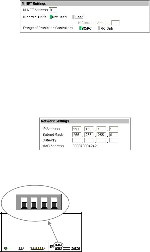
4-2-2 M-NET Setting
In M-NET Setting, set the G-50A M-NET address, whether or not a K-Control unit is present and which machines send the prohibited controller command.
(1)Enter the G-50A M-NET address in the [M-NET Address] field. Normally you should enter [0].
(2)When K-Control air conditioners are connected, click [Used] in the [K-Control Units] field and enter the M-NET address of K transmission converter in the [K Converter Address] field.
(3)If prohibited controller (prohibiting local operation) has been set, this setting determines the scope of this setting s control, i.e. operation is prohibited for both the remote control and subordinate system controllers, or just for the remote control. Click [SC/RC] when you want prohibited controllers to include both subordinate system controllers and the remote control, or click [RC only] when you only want to prohibit
operation on the remote control.
Note: Normally, you should select [SC/RC].
4-2-3 Network Setting
In Network Setting, set the G-50A IP address, subnet mask and gateway address. If connecting to the G-50A via a permanent LAN, consult with the network administrator before setting these addresses.
[Simple IP address setting of GB-50A]
The IP address that is set on the dip switch (SW2) on GB-50A main body has the priority. (Settings are shown below.) When activating the value that is set on the initial setting Web, set all the switches on SW2 to OFF.
When the number of GB-50A units is 15 or less, it is recommend to set the IP address using the dip switch (SW2) on
GB-50A main body.
SW 2
ON |
|
|
|
|
|
OFF |
|
|
|
|
|
1 |
2 |
3 |
4 |
|
|
|
|
|
SW1/2/3 |
EXT.I/O |
M-NET |
POWER LAN LINK/ACT |
1 2 3 4 5 6 |
|
|
|
|
1 |
2 |
3 |
4 |
IP Address |
OFF |
OFF |
OFF |
OFF |
IP address set by Initial Setting Web |
Note: Default IP address "192.168.1.1". |
||||
|
|
|
|
(Factory setting) |
OFF |
OFF |
OFF |
ON |
192.168.1.1 |
OFF |
OFF |
ON |
OFF |
192.168.1.2 |
OFF |
OFF |
ON |
ON |
192.168.1.3 |
OFF |
ON |
OFF |
OFF |
192.168.1.4 |
OFF |
ON |
OFF |
ON |
192.168.1.5 |
OFF |
ON |
ON |
OFF |
192.168.1.6 |
OFF |
ON |
ON |
ON |
192.168.1.7 |
ON |
OFF |
OFF |
OFF |
192.168.1.8 |
ON |
OFF |
OFF |
ON |
192.168.1.9 |
ON |
OFF |
ON |
OFF |
192.168.1.10 |
ON |
OFF |
ON |
ON |
192.168.1.11 |
ON |
ON |
OFF |
OFF |
192.168.1.12 |
ON |
ON |
OFF |
ON |
192.168.1.13 |
ON |
ON |
ON |
OFF |
192.168.1.14 |
ON |
ON |
ON |
ON |
192.168.1.15 |
Note: After changing the dip-switch settings, reset the power of GB-50A to activate the changes.
Note: If the IP address of GB-50A is forgotten, check the IP address that is registered on the monitoring PC (Web or TG-2000A) in use. GB-50A can be started temporarily by using a specified IP address. It is recommended to paste a sticker with the IP address on the unit, so that the IP address of GB-50A can be available at all times.
9
4-2-3-1 Settings for when the G-50A is connected to a dedicated LAN
(1)Enter the G-50A IP address in the [IP Address] field. If the LAN wiring has been newly set up, allocate IP addresses to the G-50A units in a sequential order starting with [192.168.1.1]. For example the first G-50A unit will receive an IP address of [192.168.1.1], the second G-50A unit will receive an IP address of [192.168.1.2] and so on.
The Web Monitor PC that monitors and sets G-50A will also require network addresses consistent with the
rest of the LAN.
Note: When using a G-50A dedicated LAN, it is recommended to set the IP address as follows.
G-50A: Between [192.168.1.1] and [192.168.1.40] Web Monitor PC: Between [192.168.1.101] and [192.168.1.150]
[Example of IP address setting]
Hub
10BASE-T LAN straight cable
G-50A No. 1 |
|
G-50A No. 2 |
|
G-50A No. 3 |
Web Monitor PC |
|
192.168.1.1 |
|
192.168.1.2 |
|
192.168.1.3 |
|
192.168.1.101 |
Note: Some hubs have a dedicated port for connection with another hub.
Connect the G-50A and Web Monitor PC to the normal ports.
(2)Enter the G-50A subnet mask in the [Subnet Mask] field. Normally, you should enter [255.255.255.0].
(3)When monitoring remotely or sending error mail via a dial-up router, enter the router IP address in the [Gateway] field.
Leave the gateway address blank when not connecting via a dial-up router.
[Example of a Remote Monitoring System]
Telecommunication Network
Dial-up router |
Dial-up router, cellular phone etc. |
IP: 192.168.1.254
G-50A |
Web Monitor PC |
Web Monitor PC |
IP Address |
:192.168.1.1 |
Subnet Mask |
:255.255.255.0 |
G/W Address |
:192.168.1.254 |
|
|
IP Address |
:192.168.1.101 |
Subnet Mask |
:255.255.255.0 |
G/W Address |
:Blank |
Note: It is recommended to set the dial-up router IP address to [192.168.1.254]. Refer to the dial-up router instruction manual for details of how to set the IP address.
Note: It is necessary to connect a modem (analog type or ISDN type) between the dial-up router and telephone line when using a dial-up router that does not have a built-in modem.
10

4-2-3-2 Settings for when the G-50A is connected to an existing LAN
When connecting the G-50A to an existing LAN, consult with the network administrator who is responsible for the LAN before setting the IP address, subnet mask, or gateway address.
[Example of a Permanent LAN System] |
Backbone LAN |
Gateway
IP: 10.130.1.250
Gateway
IP: 10.130.2.250
|
Receive from the LAN |
|
Receive from the LAN |
|
||
|
administrator. |
|
administrator. |
|
|
|
|
G-50A |
Web Monitor PC |
|
Web Monitor PC |
||
|
|
|
||||
IP Address |
:10.130.1.1 |
IP Address |
:10.130.1.101 |
|
IP Address |
:10.130.2.51 |
Subnet Mask |
:255.255.255.0 |
Subnet Mask |
:255.255.255.0 |
Subnet Mask |
:255.255.255.0 |
|
G/W Address |
:10.130.1.250 |
G/W Address |
:10.130.1.250 |
|
G/W Address |
:10.130.2.250 |
4-2-4 External Input Setting
In the External Input Setting menu, set the G-50A external input function. By using external input functions, it is possible to stop and run multiple air conditioners connected to the G-50A via the separately sold external I/O adapter for G-50A (Model: PAC-YG10HA-E) using level signals and pulse signals.
(1)Select [Not in use] when not using the external input function.
(2)Selecting [Emergency stop (Level signal)] makes it possible to stop multiple units by using a level signal. While this stop operation is being performed, operations such as running or stopping units are prohibited on the G-50A unit or remote control.
1 |
|
2 |
Emergency stop/normal |
3 |
|
4 |
|
5 |
|
6 |
DC 12V |
7 |
|
8 |
|
9 |
|
Connection to G-50A (CN2) |
|
Contact ON |
|
|
|
|
|
|
|
|
||
|
|
Emergency |
|
|
|
|
||||
Contact OFF |
|
|
|
|
|
|
|
|
||
Normal |
|
Stop |
|
|
Normal |
|||||
|
|
|||||||||
|
|
|
|
|
|
|
|
|
|
|
|
|
|
|
|
|
|
|
|
|
|
(3)Selecting [ON/OFF (Level signal)] makes it possible to run or stop multiple units using a level signal. In this mode, all air conditioner units connected to the G-50A will be run or stopped and run/stop operations will be prohibited on the G-50A unit or remote control.
1 |
|
2 |
Run/Stop |
3 |
|
4 |
|
5 |
DC12V |
6 |
|
7 |
|
8 |
|
9 |
|
Connection to G-50A (CN2) |
|
Contact ON
Contact OFF
Stop Run Stop
11
Loading...