


 Loading...
Mitsubishi Electronics FX3S-30MT, FX3S-MT, FX3G-EEPROM-32L, FX3S-30MR, FX3S-ESS-2AD User Manual
...
FX3S SERIES PROGRAMMABLE CONTROLLERS
USER'S MANUAL
Hardware Edition
Main Unit
 AC Power Type
FX3S-MR/ES
FX3S-MT/ES
FX3S-MT/ESS
FX3S-30MR/ES-2AD
FX3S-30MT/ES-2AD
FX3S-30MT/ESS-2AD
 DC Power Type
FX3S-MR/DS
FX3S-MT/DS
FX3S-MT/DSS
Display Module
FX3S-5DM
Memory Cassette
FX3G-EEPROM-32L
Safety Precautions
(Read these precautions before use.)
Before installation, operation, maintenance or inspection of this product, thoroughly read through and understand this manual and all of the associated manuals. Also, take care to handle the module properly and safely.
This manual classifies the safety precautions into two categories: 


 and
and  .
.
Indicates that incorrect handling may cause hazardous conditions, resulting in death or severe injury.
Indicates that incorrect handling may cause hazardous conditions, resulting in medium or slight personal injury or physical damage.
Depending on the circumstances, procedures indicated by 


 may also cause severe injury. It is important to follow all precautions for personal safety.
Store this manual in a safe place so that it can be taken out and read whenever necessary. Always forward it to the end user.
1. DESIGN PRECAUTIONS
Reference
•Make sure to have the following safety circuits outside of the PLC to ensure safe system operation even during external power supply problems or PLC failure.
Otherwise, malfunctions may cause serious accidents.
1)Most importantly, have the following: an emergency stop circuit, a protection circuit, an interlock circuit for
|
opposite movements (such as normal vs. reverse rotation), and an interlock circuit (to prevent damage to the |
|
|||
|
equipment at the upper and lower positioning limits). |
51 |
|||
2) |
Note that when the PLC CPU detects an error, such as a watchdog timer error, during self-diagnosis, all outputs |
||||
64 |
|||||
|
are turned off. Also, when an error that cannot be detected by the PLC CPU occurs in an input/output control |
||||
|
74 |
||||
|
block, output control may be disabled. |
||||
|
108 |
||||
|
External circuits and mechanisms should be designed to ensure safe machinery operation in such a case. |
||||
|
118 |
||||
3) |
If an overload of the 24 V DC service power supply occurs, the voltage automatically drops, inputs in the PLC |
||||
|
|||||
|
are disabled, and all outputs are turned off. |
|
|||
|
External circuits and mechanisms should be designed to ensure safe machinery operation in such a case. |
|
|||
4) |
Note that when an error occurs in a relay or transistor output device, the output could be held either on or off. |
|
|||
|
For output signals that may lead to serious accidents, external circuits and mechanisms should be designed to |
|
|||
|
ensure safe machinery operation in such a case. |
|
|||
|
|
|
|
|
|
|
|
|
|
|
|
|
|
|
|
Reference |
|
|
|
|
|
||
|
|
|
|
||
|
|
|
|
|
|
• Do not bundle the control line together with or lay it close to the main circuit or power line. As a guideline, lay the |
51 |
||||
control line at least 100 mm (3.94") or more away from the main circuit or power line. |
64 |
||||
Noise may cause malfunctions. |
74 |
||||
• Install module so that excessive force will not be applied to peripheral device connectors. |
108 |
||||
Failure to do so may result in wire damage/breakage or PLC failure. |
118 |
||||
|
|
|
|
|
|
(1)
Safety Precautions
(Read these precautions before use.)
2. INSTALLATION PRECAUTIONS
|
|
Reference |
|
|
|
||
|
|
|
|
|
|
|
|
• Make sure to cut off all phases of the power supply externally before attempting installation or wiring work. |
51 |
||
Failure to do so may cause electric shock or damage to the product. |
|||
|
|||
|
|
|
|
|
|
|
|
|
|
Reference |
|
|
|
||
|
|
|
|
|
|
|
|
•Use the product within the generic environment specifications described in Section 4.1 of this manual.
Never use the product in areas with excessive dust, oily smoke, conductive dusts, corrosive gas (salt air, Cl2, H2S, SO2 or NO2), flammable gas, vibration or impacts, or expose it to high temperature, condensation, or rain and wind. If the product is used in such conditions, electric shock, fire, malfunctions, deterioration or damage may occur.
•Do not touch the conductive parts of the product directly. Doing so may cause device failures or malfunctions.
•Install the product securely using a DIN rail or mounting screws.
•Install the product on a flat surface.
If the mounting surface is rough, undue force will be applied to the PC board, thereby causing nonconformities.
•Make sure to affix the expansion board with tapping screws. Tightening torque should follow the specifications in the manual.
If the screws are tightened outside of the specified torque range, poor connections may cause malfunctions.
• When drilling screw holes or wiring, make sure that cutting and wiring debris do not enter the ventilation slits. |
51 |
|
Failure to do so may cause fire, equipment failures or malfunctions. |
||
|
•Be sure to remove the dust proof sheet from the PLC's ventilation port when installation work is completed. Failure to do so may cause fire, equipment failures or malfunctions.
•Connect the peripheral device cables securely to their designated connectors. Loose connections may cause malfunctions.
•Connect the display module, memory cassette and expansion board securely to their designated connectors. Loose connections may cause malfunctions.
•Turn off the power to the PLC before attaching or detaching the following devices. Failure to do so may cause device failures or malfunctions.
- Peripheral devices, display module, expansion boards, special adapters and memory cassette
•Connect the memory cassette securely to the appropriate connector. Loose connections may cause malfunctions.
Installing the cassette in a raised or tilted posture can also cause malfunctions.
(2)
Safety Precautions
(Read these precautions before use.)
3. WIRING PRECAUTIONS
|
|
Reference |
|
|
|
||
|
|
|
|
|
|
|
|
• Make sure to cut off all phases of the power supply externally before attempting installation or wiring work. |
52 |
||
65 |
|||
Failure to do so may cause electric shock or damage to the product. |
|||
75 |
|||
• Make sure to attach the terminal cover, offered as an accessory, before turning on the power or initiating operation |
|||
98 |
|||
after installation or wiring work. |
|||
109 |
|||
Failure to do so may cause electric shock. |
|||
119 |
|||
|
|
||
|
|
|
|
|
|
|
|
|
|
Reference |
|
|
|
||
|
|
|
|
|
|
|
|
•Do not supply power to the [24V] terminal (24 V DC service power supply) on the main unit. Doing so may cause damage to the product.
•Perform class D grounding (grounding resistance: 100 Ω or less) to the grounding terminal on the main unit with a wire 2 mm2 or thicker.
Do not use common grounding with heavy electrical systems (refer to Section 8.3).
•Connect the AC power supply wiring to the dedicated terminals described in this manual.
If an AC power supply is connected to a DC input/output terminal or DC power supply terminal, the PLC will burn out.
•Noise resistance may be lower when the L and N wires of an AC power supply are not wired correctly. Please wire using the correct polarity.
•Connect the DC power supply wiring to the dedicated terminals described in this manual.
If an AC power supply is connected to a DC input/output terminal or DC power supply terminal, the PLC will burn out.
•Do not wire vacant terminals externally. Doing so may damage the product.
•When drilling screw holes or wiring, make sure cutting or wire debris does not enter the ventilation slits.
Failure to do so may cause fire, equipment failures or malfunctions. |
52 |
• Make sure to observe the following precautions in order to prevent any damage to the machinery or accidents due |
|
to abnormal data written to the PLC under the influence of noise: |
65 |
1) Do not bundle the power line or shield of the analog input/output cable together with or lay it close to the main |
75 |
circuit, high-voltage line, or load line. |
98 |
Otherwise, noise disturbance and/or surge induction are likely to take place. As a guideline, lay the control line |
109 |
at least 100 mm (3.94") or more away from the main circuit, high-voltage line, or load line. |
112 |
2) Ground the shield of the analog input/output cable at one point on the signal receiving side. |
116 |
However, do not use common grounding with heavy electrical systems. |
117 |
• Make sure to properly wire to the main unit in accordance with the following precautions. |
119 |
Failure to do so may cause electric shock, equipment failures, a short-circuit, wire breakage, malfunctions, or |
|
damage to the product. |
|
-Make sure to properly wire to the main unit in accordance with the rated voltage, current, and frequency of each terminal.
-The disposal size of the cable end should follow the dimensions described in the manual.
-Tightening torque should follow the specifications in the manual.
-Tighten the screws using a Phillips-head screwdriver No.2 (shaft diameter 6mm (0.24”) or less). Make sure that the screwdriver does not touch the partition part of the terminal block.
•Make sure to properly wire to the terminal block (European type) in accordance with the following precautions. Failure to do so may cause electric shock, equipment failures, a short-circuit, wire breakage, malfunctions, or damage to the product.
-The disposal size of the cable end should follow the dimensions described in the manual.
-Tightening torque should follow the specifications in the manual.
-Twist the end of strand wire and make sure that there are no loose wires.
-Do not solder-plate the electric wire ends.
-Do not connect more than the specified number of wires or electric wires of unspecified size.
-Affix the electric wires so that neither the terminal block nor the connected parts are directly stressed.
(3)

Safety Precautions
(Read these precautions before use.)
4. STARTUP AND MAINTENANCE PRECAUTIONS
|
|
Reference |
|
|
|
|
|
|
|
|
|
• Do not touch any terminal while the PLC's power is on. |
|
|
Doing so may cause electric shock or malfunctions. |
|
|
• Before cleaning or retightening terminals, cut off all phases of the power supply externally. |
|
|
Failure to do so may cause electric shock. |
|
|
• Before modifying or disrupting the program in operation or running the PLC, carefully read through this manual and |
125 |
|
the associated manuals and ensure the safety of the operation. |
152 |
|
An operation error may damage the machinery or cause accidents. |
|
|
•Do not change the program in the PLC from two or more peripheral equipment devices at the same time. (i.e. from a programming tool and a GOT)
Doing so may cause destruction or malfunction of the PLC program.
Reference
•Turn off the power to the PLC before attaching or detaching the memory cassette. If the memory cassette is attached or detached while the PLC's power is on, the data in the memory may be destroyed, or the memory cassette may be damaged.
•Do not disassemble or modify the PLC.
Doing so may cause fire, equipment failures, or malfunctions. |
125 |
For repair, contact your local Mitsubishi Electric representative. |
152 |
• Turn off the power to the PLC before connecting or disconnecting any connection cable. |
177 |
Failure to do so may cause equipment failures or malfunctions. |
|
•Turn off the power to the PLC before attaching or detaching the following devices. Failure to do so may cause equipment failures or malfunctions.
- Peripheral devices, display module, expansion boards, special adapters and memory cassette
5. DISPOSAL PRECAUTIONS
|
|
|
Reference |
|
|
|
|
||
|
|
|
|
|
|
|
|
|
|
• Please contact a certified electronic waste disposal company for the environmentally safe recycling and disposal of |
125 |
|||
your device. |
||||
|
||||
|
|
|
|
|
6. TRANSPORTATION AND STORAGE PRECAUTIONS
Reference
•The PLC is a precision instrument. During transportation, avoid impacts larger than those specified in the general
specifications (Section 4.1) using dedicated packaging boxes and shock-absorbing palettes. Failure to do so may |
125 |
|
cause failures in the PLC. |
||
|
||
After transportation, verify operation of the product and check for damage of the mounting part, etc. |
|
(4)

FX3S Series Programmable Controllers
User's Manual - Hardware Edition
FX3S Series Programmable Controllers
User's Manual [Hardware Edition]
Manual number |
JY997D48601 |
|
|
Manual revision |
C |
|
|
Date |
10/2014 |
|
|
Foreword
This manual contains text, diagrams and explanations which will guide the reader in the correct installation, safe use and operation of the FX3S Series Programmable Controllers and should be read and understood before attempting to install or use the unit.
And, store this manual in a safe place so that you can take it out and read it whenever necessary. Always forward it to the end user.
This manual confers no industrial property rights or any rights of any other kind, nor does it confer any patent licenses. Mitsubishi Electric Corporation cannot be held responsible for any problems involving industrial property rights which may occur as a result of using the contents noted in this manual.
© 2013 MITSUBISHI ELECTRIC CORPORATION
1

FX3S Series Programmable Controllers
User's Manual - Hardware Edition
Outline Precautions
•This manual provides information for the use of the FX3S Series Programmable Controllers. The manual has been written to be used by trained and competent personnel. The definition of such a person or persons is as follows;
a)Any engineer who is responsible for the planning, design and construction of automatic equipment using the product associated with this manual should be of a competent nature, trained and qualified to the local and national standards required to fulfill that role. These engineers should be fully aware of all aspects of safety with regards to automated equipment.
b)Any commissioning or service engineer must be of a competent nature, trained and qualified to the local and national standards required to fulfill that job. These engineers should also be trained in the use and maintenance of the completed product. This includes being completely familiar with all associated documentation for the said product. All maintenance should be carried out in accordance with established safety practices.
c)All operators of the completed equipment should be trained to use that product in a safe and coordinated manner in compliance to established safety practices. The operators should also be familiar with documentation which is connected with the actual operation of the completed equipment.
Note: The term 'completed equipment' refers to a third party constructed device which contains or uses the product associated with this manual
•This product has been manufactured as a general-purpose part for general industries, and has not been designed or manufactured to be incorporated in a device or system used in purposes related to human life.
•Before using the product for special purposes such as nuclear power, electric power, aerospace, medicine or passenger movement vehicles, consult with Mitsubishi Electric.
•This product has been manufactured under strict quality control. However when installing the product where major accidents or losses could occur if the product fails, install appropriate backup or failsafe functions in the system.
•When combining this product with other products, please confirm the standard and the code, or regulations with which the user should follow. Moreover, please confirm the compatibility of this product to the system, machine, and apparatus with which a user is using.
•If in doubt at any stage during the installation of the product, always consult a professional electrical engineer who is qualified and trained to the local and national standards. If in doubt about the operation or use, please consult your local Mitsubishi Electric representative.
•Since the examples indicated by this manual, technical bulletin, catalog, etc. are used as a reference, please use it after confirming the function and safety of the equipment and system. Mitsubishi Electric will accept no responsibility for actual use of the product based on these illustrative examples.
•This manual content, specification etc. may be changed without a notice for improvement.
•The information in this manual has been carefully checked and is believed to be accurate; however, if you have noticed a doubtful point, a doubtful error, etc., please contact your local Mitsubishi Electric representative.
Registration
•Microsoft and Windows are either registered trademarks or trademarks of Microsoft Corporation in the United States and/or other countries.
•Ethernet is a trademark of Xerox Corporation.
•MODBUS is a registered trademark of Schneider Electric SA.
•Phillips is a registered trademark of Phillips Screw Company.
•The company name and the product name to be described in this manual are the registered trademarks or trademarks of each company.
2

FX3S Series Programmable Controllers |
|
User's Manual - Hardware Edition |
Table of Contents |
Table of Contents
SAFETY PRECAUTIONS .................................................................................................. |
(1) |
Standards................................................................................................................................. |
10 |
Certification of UL, cUL standards ..................................................................................................... |
10 |
Compliance with EC directive (CE Marking) ...................................................................................... |
10 |
Requirement for Compliance with EMC directive .................................................................................. |
10 |
Requirement for Compliance with LVD directive ................................................................................... |
11 |
Caution for compliance with EC Directive ............................................................................................. |
12 |
1. Introduction |
13 |
||
|
|
|
|
1.1 |
Introduction of Manuals................................................................................................................. |
13 |
|
|
1.1.1 |
Classification of major components in this manual........................................................................ |
13 |
|
1.1.2 |
Manual organization and position of this manual .......................................................................... |
14 |
|
1.1.3 |
List of manuals .............................................................................................................................. |
15 |
1.2 |
Generic Names and Abbreviations Used in Manuals.................................................................... |
18 |
|
2. Features and Part Names |
19 |
||
|
|
|
|
2.1 |
Major Features .............................................................................................................................. |
19 |
|
2.2 |
Names and Functions of Parts...................................................................................................... |
21 |
|
|
2.2.1 |
Front Panel .................................................................................................................................... |
21 |
|
2.2.2 |
Sides.............................................................................................................................................. |
23 |
3. Introduction of Products |
24 |
|
|
|
|
3.1 List of Products and Interpretation of Model Names ..................................................................... |
24 |
|
3.1.1 |
Main units ...................................................................................................................................... |
25 |
3.1.2 |
Expansion boards.......................................................................................................................... |
26 |
3.1.3 |
Connector conversion adapter ...................................................................................................... |
26 |
3.1.4 |
Special adapters............................................................................................................................ |
26 |
3.1.5 |
Display module.............................................................................................................................. |
26 |
3.1.6 |
Memory cassette ........................................................................................................................... |
26 |
3.2 Connector Types and Cables for Program Communication.......................................................... |
27 |
|
3.2.1 |
Programming tool .......................................................................................................................... |
28 |
3.2.2 |
Communication cables .................................................................................................................. |
28 |
3.2.3 |
Converters and interface ............................................................................................................... |
28 |
4. Specifications, External Dimensions and Terminal Layout (Main Units) |
29 |
||
|
|
|
|
4.1 |
Generic Specifications .................................................................................................................. |
29 |
|
|
4.1.1 |
Dielectric withstand voltage test and insulation resistance test..................................................... |
30 |
4.2 |
Power Supply Specifications......................................................................................................... |
30 |
|
|
4.2.1 AC power type............................................................................................................................... |
30 |
|
|
4.2.2 DC power type............................................................................................................................... |
30 |
|
4.3 |
Input Specifications....................................................................................................................... |
31 |
|
|
4.3.1 |
24 V DC Input (sink/source) .......................................................................................................... |
31 |
4.4 |
Output Specifications .................................................................................................................... |
32 |
|
|
4.4.1 |
Relay output specifications............................................................................................................ |
32 |
|
4.4.2 |
Transistor output specifications ..................................................................................................... |
33 |
4.5 |
Performance Specifications .......................................................................................................... |
34 |
|
4.6 |
External Dimensions (Weight/Accessories/Installation) ................................................................ |
36 |
|
|
4.6.1 |
Main units ...................................................................................................................................... |
36 |
3

FX3S Series Programmable Controllers |
|
|
|||
User's Manual - Hardware Edition |
Table of Contents |
||||
|
|
|
|
|
|
4.7 |
Terminal Layout ............................................................................................................................ |
37 |
|
||
|
|
4.7.1 |
Interpretation of terminal block layout............................................................................................ |
37 |
|
|
|
4.7.2 FX3S-10M................................................................................................................................... |
38 |
|
|
|
|
4.7.3 FX3S-14M................................................................................................................................... |
38 |
|
|
|
|
4.7.4 FX3S-20M................................................................................................................................... |
39 |
|
|
|
|
4.7.5 FX3S-30M................................................................................................................................... |
39 |
|
|
|
|
|
|
||
|
5. Version Information and Peripheral Equipment Connectability |
40 |
|
||
|
|
|
|
|
|
5.1 |
Version Information....................................................................................................................... |
40 |
|
||
|
|
5.1.1 |
Manufacturer's serial number check method................................................................................. |
40 |
|
|
|
5.1.2 |
Version check method ................................................................................................................... |
41 |
|
|
|
5.1.3 |
Version upgrade history................................................................................................................. |
41 |
|
5.2 |
Programming Tool Applicability..................................................................................................... |
41 |
|
||
|
|
5.2.1 |
Applicable versions of programming tool....................................................................................... |
41 |
|
|
|
5.2.2 |
In the case of programming tool (version) not applicable.............................................................. |
41 |
|
|
|
5.2.3 |
Program transfer speed and programming tools ........................................................................... |
42 |
|
|
|
5.2.4 |
Cautions on connecting peripheral equipment by way of expansion board or special adapter..... 42 |
||
|
|
5.2.5 |
Cautions on write during RUN ....................................................................................................... |
43 |
|
5.3 |
Use of (Built-in USB) Programming Port....................................................................................... |
45 |
|
||
|
|
5.3.1 |
Installation of USB driver............................................................................................................... |
45 |
|
|
|
5.3.2 |
Setting in GX Works2 .................................................................................................................... |
45 |
|
5.4 |
Cautions on using FA transparent function in GOT1000 Series ................................................... |
46 |
|
||
5.5 |
Cautions on using transparent port (2-port) function of GOT-F900 Series ................................... |
47 |
|
||
5.6 |
Other Peripheral Equipment Applicability...................................................................................... |
48 |
|
||
|
|
5.6.1 |
Other peripheral equipment applicability ....................................................................................... |
48 |
|
|
|
|
|
||
|
6. Examination of System Configuration |
49 |
|
||
|
|
|
|
|
|
6.1 |
Configuration of a Whole System.................................................................................................. |
49 |
|
||
|
|
6.1.1 |
Expansion board/connector conversion adapter/memory cassette system configuration............. |
49 |
|
|
|
6.1.2 |
Special adapter system configuration............................................................................................ |
50 |
|
|
|
|
|
||
|
7. Installation In Enclosure |
51 |
|
||
|
|
|
|
|
|
7.1 |
Installation location........................................................................................................................ |
53 |
|
||
|
|
7.1.1 |
Installation location in enclosure.................................................................................................... |
53 |
|
|
|
7.1.2 |
Space in enclosure........................................................................................................................ |
53 |
|
7.2 |
Examination for Installing Method in Enclosure ............................................................................ |
54 |
|
||
7.3 |
Procedures for Installing on and Detaching from DIN Rail............................................................ |
54 |
|
||
|
|
7.3.1 |
Preparation for installation............................................................................................................. |
54 |
|
|
|
7.3.2 |
Installation of main unit.................................................................................................................. |
55 |
|
|
|
7.3.3 |
Removal of main unit..................................................................................................................... |
56 |
|
7.4 |
Procedures for Installing Directly (with M4 screws) ...................................................................... |
57 |
|
||
|
|
7.4.1 |
Hole pitches for direct mounting.................................................................................................... |
57 |
|
|
|
7.4.2 |
Example of mounting hole pitches................................................................................................. |
58 |
|
|
|
7.4.3 |
Installation of main unit.................................................................................................................. |
58 |
|
7.5 |
Connecting Methods for Main Unit and Extension Devices .......................................................... |
58 |
|
||
|
|
7.5.1 |
Connection of extension devices................................................................................................... |
58 |
|
|
|
7.5.2 |
Connecting method A - connection of expansion board................................................................ |
59 |
|
|
|
7.5.3 |
Connecting method B - connection of connector conversion adapter ........................................... |
60 |
|
|
|
7.5.4 |
Connecting method C - connection of special adapter.................................................................. |
61 |
|
7.6 |
Application of labels ...................................................................................................................... |
62 |
|
||
|
|
7.6.1 |
Application of Station No. label (FX3G-485-BD)............................................................................ |
62 |
|
|
|
7.6.2 |
Application of Station No. label (FX3G-485-BD-RJ) ...................................................................... |
62 |
|
|
|
7.6.3 |
Application of trimmer layout Label (FX3G-8AV-BD)..................................................................... |
63 |
|
4
FX3S Series Programmable Controllers |
|
|
|||
User's Manual - Hardware Edition |
Table of Contents |
||||
|
|
|
|
||
|
|
|
|
||
|
8. Preparation for Wiring and Power Supply Wiring Procedures |
64 |
|
||
|
|
|
|
|
|
8.1 |
Preparation for Wiring ................................................................................................................... |
66 |
|
||
8.1.1 |
Wiring procedures ......................................................................................................................... |
66 |
|
||
|
8.2 Cable Connecting Procedures ...................................................................................................... |
67 |
|
||
8.2.1 |
Terminal block [Main unit].............................................................................................................. |
67 |
|
||
8.2.2 |
Terminal block (for European) [expansion board and special adapters] ....................................... |
68 |
|
||
8.2.3 |
Grounding terminal of the FX3G-485-BD-RJ ................................................................................. |
69 |
|
||
|
8.2.4 Grounding terminal of the FX3U-ENET-ADP................................................................................. |
70 |
|
||
|
8.3 Grounding ..................................................................................................................................... |
71 |
|
||
8.4 |
Examples of External Wiring [AC power type] .............................................................................. |
72 |
|
||
8.5 |
Examples of External Wiring [DC power type] .............................................................................. |
73 |
|
||
|
|
|
|
||
|
9. Input Wiring Procedures |
74 |
|
||
|
|
|
|
|
|
9.1 |
Before Starting Input Wiring.......................................................................................................... |
76 |
|
||
9.1.1 |
Sink and source input.................................................................................................................... |
76 |
|
||
9.2 |
24 V DC input (Sink and source input type) .................................................................................. |
77 |
|
||
9.2.1 |
Handling of 24 V DC input ............................................................................................................. |
77 |
|
||
9.2.2 |
Instructions for connecting input devices....................................................................................... |
78 |
|
||
9.2.3 |
Examples of external wiring [AC power type] ................................................................................ |
80 |
|
||
9.2.4 |
Examples of external wiring [DC power type]................................................................................ |
81 |
|
||
9.3 |
Input Interruption (I00 to I50) .................................................................................................. |
82 |
|
||
9.3.1 |
Allocation of pointers to input numbers (input signal ON/OFF duration) ....................................... |
82 |
|
||
9.3.2 |
Cautions for input interruption ....................................................................................................... |
82 |
|
||
9.3.3 |
Examples of external wiring........................................................................................................... |
83 |
|
||
|
9.4 Pulse Catch (M8170 to M8175) .................................................................................................... |
84 |
|
||
9.4.1 |
Allocation of special memories to input numbers (ON duration of input signals) .......................... |
84 |
|
||
9.4.2 |
Cautions for pulse catch................................................................................................................ |
84 |
|
||
9.4.3 |
Examples of external wiring........................................................................................................... |
85 |
|
||
|
|
|
|
||
|
10. Use of High-speed Counters |
86 |
|
||
|
|
|
|
|
|
10.1 |
Outline......................................................................................................................................... |
86 |
|
||
10.2 |
Types of Counting and Operations ............................................................................................. |
86 |
|
||
10.2.1 |
Types and input signal forms....................................................................................................... |
86 |
|
||
10.2.2 |
High-speed counter device notations .......................................................................................... |
86 |
|
||
10.2.3 |
Cautions in connecting mating device ......................................................................................... |
86 |
|
||
10.3 |
List of Device Numbers and Functions ....................................................................................... |
87 |
|
||
10.4 |
Allocation of Device Numbers to Input Numbers ........................................................................ |
88 |
|
||
10.4.1 |
Allocation table ............................................................................................................................ |
88 |
|
||
10.4.2 |
Restriction of redundant use of input numbers............................................................................ |
88 |
|
||
10.5 |
Handling of High-speed Counters ............................................................................................... |
89 |
|
||
10.5.1 |
1-phase 1-count input.................................................................................................................. |
89 |
|
||
10.5.2 |
1-phase 2-count input.................................................................................................................. |
90 |
|
||
10.5.3 |
2-phase 2-count input.................................................................................................................. |
91 |
|
||
10.6 |
Timing of Updating of Current Value and Comparison of Current Value .................................... |
92 |
|
||
10.6.1 |
Timing of updating of current value ............................................................................................. |
92 |
|
||
10.6.2 |
Comparison of current value ....................................................................................................... |
92 |
|
||
|
10.7 Response Frequency and Overall Frequency............................................................................. |
93 |
|
||
10.8 |
Examples of External Wiring (Rotary Encoder)........................................................................... |
94 |
|
||
10.8.1 |
1-phase 1-input [C235 to C245] .................................................................................................. |
94 |
|
||
10.8.2 |
2-phase 2-input [C251 to C255] .................................................................................................. |
95 |
|
||
10.9 |
Related Devices and Function Switching Procedures ................................................................ |
96 |
|
||
10.9.1 |
Related devices ........................................................................................................................... |
96 |
|
||
10.9.2 |
[Function switching] switching of allocation and functions of input terminals .............................. |
97 |
|
||
|
10.10 Cautions on Use........................................................................................................................ |
97 |
|
||
5

FX3S Series Programmable Controllers |
|
|
|||
User's Manual - Hardware Edition |
Table of Contents |
||||
|
|
|
|
||
|
|
|
|
||
|
11. Use of Built-in Analog |
98 |
|
||
|
|
|
|
|
|
11.1 |
Outline......................................................................................................................................... |
99 |
|
||
11.2 |
Built-in variable analog potentiometer function ........................................................................... |
99 |
|
||
11.2.1 |
Outline of functions...................................................................................................................... |
99 |
|
||
11.2.2 |
Applicable PLC ............................................................................................................................ |
99 |
|
||
11.2.3 |
Special data register.................................................................................................................... |
99 |
|
||
11.2.4 |
Use example of variable analog potentiometer ......................................................................... |
100 |
|
||
11.3 |
Built-in analog input function..................................................................................................... |
101 |
|
||
11.3.1 |
Outline of functions.................................................................................................................... |
101 |
|
||
11.3.2 |
Applicable PLC .......................................................................................................................... |
101 |
|
||
11.3.3 |
Analog input performance specifications................................................................................... |
101 |
|
||
11.3.4 |
Analog input terminal block ....................................................................................................... |
102 |
|
||
11.3.5 |
Terminal layout .......................................................................................................................... |
103 |
|
||
11.3.6 |
Analog input line........................................................................................................................ |
103 |
|
||
11.3.7 |
Special data register.................................................................................................................. |
103 |
|
||
|
11.3.8 Program example ...................................................................................................................... |
105 |
|
||
11.3.9 |
Changing of input characteristics .............................................................................................. |
105 |
|
||
11.3.10 |
Troubleshooting when using built-in analog input ................................................................... |
106 |
|
||
|
|
|
|
||
|
12. Output Wiring Procedures |
108 |
|
||
|
|
|
|
|
|
12.1 |
External Wiring for Relay Output Type...................................................................................... |
110 |
|
||
12.1.1 |
Product life of relay contacts ..................................................................................................... |
110 |
|
||
12.1.2 |
Handling of relay output............................................................................................................. |
110 |
|
||
12.1.3 |
External wiring precautions ....................................................................................................... |
111 |
|
||
12.1.4 |
Example of external wiring ........................................................................................................ |
112 |
|
||
12.2 |
External Wiring of Transistor Output (Sink/Source) Type ......................................................... |
113 |
|
||
12.2.1 |
Transistor Output Sink and Source ........................................................................................... |
113 |
|
||
12.2.2 |
Handling of transistor output...................................................................................................... |
113 |
|
||
12.2.3 |
External wiring precautions ....................................................................................................... |
115 |
|
||
12.2.4 |
Example of external wiring ........................................................................................................ |
116 |
|
||
|
|
|
|
||
|
13. Examples of Wiring for Various Uses |
118 |
|
||
|
|
|
|
|
|
13.1 |
Notes about Examples of Wiring............................................................................................... |
119 |
|
||
13.2 |
Digital Switch [DSW Instruction (FNC 72)/BIN Instruction (FNC 19)] ....................................... |
120 |
|
||
|
13.2.1 When DSW instruction (FNC 72) is used .................................................................................. |
120 |
|
||
13.2.2 |
When BIN instruction (FNC 19) is used..................................................................................... |
121 |
|
||
13.3 |
Input Matrix [MTR Instruction (FNC 52)] ................................................................................... |
122 |
|
||
13.4 |
Seven Segment with Latch [SEGL Instruction (FNC 74)/BCD Instruction (FNC 18)] ............... |
123 |
|
||
|
13.4.1 When SEGL instruction (FNC 74) is used ................................................................................. |
123 |
|
||
|
13.4.2 When BCD instruction (FNC 18) is used ................................................................................... |
124 |
|
||
|
|
|
|
||
|
14. Test Operation, Adjustment, Maintenance and Troubleshooting |
125 |
|
||
|
|
|
|
|
|
14.1 |
Preparation for Test Operation.................................................................................................. |
126 |
|
||
14.1.1 |
Preliminary inspection [power OFF] .......................................................................................... |
126 |
|
||
14.1.2 |
Connection to peripheral device connecting connector (RS-422) ............................................. |
126 |
|
||
14.1.3 |
Connection to peripheral device connecting connector (USB) .................................................. |
127 |
|
||
|
14.1.4 Writing of program and program check [power ON and PLC stopped] ..................................... |
127 |
|
||
14.2 |
Running and Stopping Procedures [Power ON]........................................................................ |
128 |
|
||
14.2.1 |
Methods of running and stopping .............................................................................................. |
128 |
|
||
14.2.2 |
Use of several running/stopping methods ................................................................................. |
129 |
|
||
14.3 |
Operation and Test [Power ON and PLC Running] .................................................................. |
130 |
|
||
14.3.1 |
Self-diagnostic function ............................................................................................................. |
130 |
|
||
14.3.2 |
Test functions ............................................................................................................................ |
130 |
|
||
6

FX3S Series Programmable Controllers |
|
|
|||
User's Manual - Hardware Edition |
Table of Contents |
||||
|
|
|
|
|
|
14.3.3 |
Program modification function ................................................................................................... |
130 |
|
||
14.4 |
Maintenance and Periodic Inspection ....................................................................................... |
131 |
|
||
14.4.1 |
Periodic inspection .................................................................................................................... |
131 |
|
||
14.4.2 |
Maintenance - product life of relay contacts ............................................................................. |
131 |
|
||
14.5 |
Troubleshooting with LEDs ....................................................................................................... |
132 |
|
||
14.5.1 |
POW LED [on/flashing/off]......................................................................................................... |
132 |
|
||
14.5.2 |
ERR LED [on/flashing/off].......................................................................................................... |
132 |
|
||
14.6 |
Judgment by Error Codes and Representation of Error Codes ................................................ |
133 |
|
||
|
14.6.1 Operation and check by GX Works2 ......................................................................................... |
133 |
|
||
14.6.2 |
Representation of errors............................................................................................................ |
134 |
|
||
14.6.3 |
Error Code List and Action ........................................................................................................ |
135 |
|
||
14.7 |
Troubleshooting ........................................................................................................................ |
140 |
|
||
14.7.1 |
Output does not operate............................................................................................................ |
140 |
|
||
|
14.7.2 24 V DC input does not operate ................................................................................................ |
140 |
|
||
14.7.3 |
Cautions in registering keyword ................................................................................................ |
141 |
|
||
|
|
|
|
||
|
15. Other Extension Devices and Optional Units |
|
|
||
|
(External Dimensions and Terminal Arrangement) |
142 |
|
||
|
|
|
|
|
|
15.1 |
Special Adapters ....................................................................................................................... |
142 |
|
||
|
15.1.1 FX3U-4AD-ADP ......................................................................................................................... |
142 |
|
||
|
15.1.2 FX3U-4DA-ADP ......................................................................................................................... |
142 |
|
||
|
15.1.3 FX3U-3A-ADP............................................................................................................................ |
143 |
|
||
|
15.1.4 FX3U-4AD-PT(W)-ADP ............................................................................................................. |
143 |
|
||
|
15.1.5 FX3U-4AD-PNK-ADP ................................................................................................................ |
143 |
|
||
|
15.1.6 FX3U-4AD-TC-ADP ................................................................................................................... |
144 |
|
||
|
15.1.7 FX3U-232ADP(-MB) .................................................................................................................. |
144 |
|
||
|
15.1.8 FX3U-485ADP(-MB) .................................................................................................................. |
145 |
|
||
|
15.1.9 FX3U-ENET-ADP ...................................................................................................................... |
145 |
|
||
15.2 |
Expansion Board....................................................................................................................... |
146 |
|
||
|
15.2.1 FX3G-4EX-BD ........................................................................................................................... |
146 |
|
||
|
15.2.2 FX3G-2EYT-BD ......................................................................................................................... |
146 |
|
||
|
15.2.3 FX3G-232-BD ............................................................................................................................ |
147 |
|
||
|
15.2.4 FX3G-422-BD ............................................................................................................................ |
147 |
|
||
|
15.2.5 FX3G-485-BD ............................................................................................................................ |
148 |
|
||
|
15.2.6 FX3G-485-BD-RJ....................................................................................................................... |
148 |
|
||
|
15.2.7 FX3G-2AD-BD ........................................................................................................................... |
149 |
|
||
|
15.2.8 FX3G-1DA-BD ........................................................................................................................... |
149 |
|
||
|
15.2.9 FX3G-8AV-BD ........................................................................................................................... |
150 |
|
||
15.3 |
Connector Conversion Adapter................................................................................................. |
151 |
|
||
|
15.3.1 FX3S-CNV-ADP......................................................................................................................... |
151 |
|
||
15.4 |
Interface Module ....................................................................................................................... |
151 |
|
||
|
15.4.1 FX-232AWC-H........................................................................................................................... |
151 |
|
||
|
|
|
|
||
|
16. Display Module (FX3S-5DM) |
152 |
|
||
|
|
|
|
|
|
16.1 |
Specifications ............................................................................................................................ |
152 |
|
||
16.1.1 |
Applicable PLC .......................................................................................................................... |
152 |
|
||
16.1.2 |
Display Specifications................................................................................................................ |
152 |
|
||
|
16.1.3 External Dimensions and Part Names....................................................................................... |
153 |
|
||
16.2 |
Installation and Removal........................................................................................................... |
153 |
|
||
16.2.1 |
Installation and Removal |
|
|
||
|
|
|
(when the expansion board/connector conversion adapter is not used together)...................... |
153 |
|
16.2.2 |
Installation and Removal |
|
|
||
|
|
|
(when the expansion board/connector conversion adapter is used together)............................ |
154 |
|
16.3 |
Summary of Functions .............................................................................................................. |
155 |
|
||
16.4 |
Flowing of the Screen Display................................................................................................... |
156 |
|
||
16.5 |
Monitor/Test .............................................................................................................................. |
157 |
|
||
16.5.1 |
Relevant devices ....................................................................................................................... |
157 |
|
||
16.5.2 |
Selecting a device ..................................................................................................................... |
157 |
|
||
7

FX3S Series Programmable Controllers |
|
|
|
|||||
User's Manual - Hardware Edition |
Table of Contents |
|||||||
|
|
|
|
|
|
|||
16.5.3 |
When "Input (X)", "Output (Y)", "Auxiliary relay (M)" or "State (S)" is selected ......................... |
|
158 |
|
||||
16.5.4 |
When "Timer (T)" is selected..................................................................................................... |
|
160 |
|
||||
16.5.5 |
When "Counter (C)" is selected................................................................................................. |
|
162 |
|
||||
16.5.6 |
When "Data register (D)" is selected ......................................................................................... |
|
164 |
|
||||
16.6 |
Time Display and Setting .......................................................................................................... |
|
166 |
|
||||
16.7 |
Error Display |
............................................................................................................................. |
|
166 |
|
|||
16.8 |
5DM Control ......................................................................Functions (Restrictions From PLC) |
|
167 |
|
||||
16.8.1 |
System information ..............................................................................................................list |
|
167 |
|
||||
16.8.2 |
System information ...........................................................................setting program example |
|
168 |
|
||||
16.9 |
Specified Device ............................................................................................Monitor Function |
|
168 |
|
||||
16.9.1 |
System information ............................................................- specified device monitor function |
|
168 |
|
||||
16.9.2 |
Program ....................................................................................................................example1 |
|
169 |
|
||||
16.9.3 |
Program ...................example2 (when monitoring consecutive timers using operation button) |
|
170 |
|
||||
16.9.4 |
Program ..........example3 (when monitoring non-consecutive timers using operation buttons) |
|
171 |
|
||||
16.9.5 |
Specified ...............................................................................................device editing function |
|
172 |
|
||||
16.10 |
Back light off ..............................................................................................................function |
|
174 |
|
||||
16.10.1 |
System ............................................................................Information - Back light off function |
|
174 |
|
||||
16.11 |
Display Screen .............................................................................................Protect Function |
|
175 |
|
||||
16.11.1 |
System ..............................................................information - display screen protect function |
|
175 |
|
||||
16.11.2 |
Program .................................................................example (screen protect function setting) |
|
175 |
|
||||
16.12 |
Error display ....................................................................................................enable/disable |
|
175 |
|
||||
16.13 |
Operation Button ...................................................................................ON/OFF Information |
|
176 |
|
||||
16.13.1 |
Various ................................................................................................................applications |
|
176 |
|
||||
16.13.2 |
System ...................................................information - operation button ON/OFF information |
|
176 |
|
||||
16.14 |
Specifying a ........................................Decimal/Hexadecimal Current Value Display Format |
|
176 |
|
||||
|
|
|
|
|
||||
|
17. Memory Cassette |
|
177 |
|
||||
|
|
|
|
|
|
|
|
|
17.1 |
Outline....................................................................................................................................... |
|
|
|
177 |
|
||
17.2 |
Specifications ............................................................................................................................ |
|
177 |
|
||||
17.2.1 |
Electrical .............................................................................................................specifications |
|
177 |
|
||||
17.2.2 |
Part names ........................................................................................and external dimensions |
|
177 |
|
||||
17.3 |
Installation................................................................................................................................. |
|
|
178 |
|
|||
17.3.1 |
Installation ...(when the expansion board/connector conversion adapter is not used together) |
178 |
|
|||||
17.3.2 |
Installation .........(when the expansion board/connector conversion adapter is used together) |
179 |
|
|||||
17.4 |
Removal .................................................................................................................................... |
|
|
|
181 |
|
||
17.4.1 |
Removal ...(when the expansion board/connector conversion adapter are not used together) |
181 |
|
|||||
17.4.2 |
Removal .........(when the expansion board/connector conversion adapter are used together) |
182 |
|
|||||
17.5 |
Saved Data Content.................................................................................................................. |
|
183 |
|
||||
17.6 |
PROTECT Switch ..................................................................................................................... |
|
184 |
|
||||
17.6.1 |
PROTECT ...........................................................................................................switch setting |
|
184 |
|
||||
|
17.6.2 PROTECT switch operation ...................................................................................................... |
|
184 |
|
||||
17.6.3 |
Precautions .........................................................................when setting and using the switch |
|
184 |
|
||||
17.7 |
Memory Cassette .......................<-> PLC (EEPROM Memory) Transfers by Loader Function |
|
185 |
|
||||
|
17.7.1 Writing (WR: FX3G-EEPROM-32L -> PLC)............................................................................... |
|
185 |
|
||||
|
17.7.2 Reading (RD: FX3G-EEPROM-32L <- PLC) ............................................................................. |
|
186 |
|
||||
17.8 |
Memory cassette .......................................................................................precautions for use |
|
186 |
|
||||
|
|
|
|
|
||||
|
Appendix A: Special Device List |
|
187 |
|
||||
|
|
|
|
|
|
|||
|
Appendix A-1 |
Special Auxiliary Relay (M8000 to M8511) ........................................................ |
|
187 |
|
|||
|
Appendix A-2 |
Special ...........................................................Data Register (D8000 to D8511) |
|
193 |
|
|||
|
Appendix A-3 Analog expansion boards [M8260 to M8269 and D8260 to D8269] .................. |
|
198 |
|
||||
|
Appendix A-3-1 ................................................................. |
Special auxiliary relays (M8260 to M8269) |
|
198 |
|
|||
|
Appendix A-3-2 .................................................................... |
Special data registers (D8260 to D8269) |
|
198 |
|
|||
|
Appendix A-4 Analog special adapters [M8280 to M8289 and D8280 to D8289]..................... |
|
199 |
|
||||
|
Appendix A-4-1 ................................................................. |
Special auxiliary relays (M8280 to M8289) |
|
199 |
|
|||
|
Appendix A-4-2 .................................................................... |
Special data registers (D8280 to D8289) |
|
200 |
|
|||
8

FX3S Series Programmable Controllers |
|
|
User's Manual - Hardware Edition |
Table of Contents |
|
Appendix B: Instruction List |
201 |
|
Appendix B-1 |
Basic Instructions ............................................................................................... |
201 |
Appendix B-2 |
Step Ladder Instructions .................................................................................... |
201 |
Appendix B-3 |
Applied Instructions ... in Ascending Order of FNC Number.............................. |
202 |
Appendix C: Discontinued models |
205 |
|
Warranty................................................................................................................................. |
|
207 |
Revised History |
..................................................................................................................... |
208 |
9

FX3S Series Programmable Controllers |
|
User's Manual - Hardware Edition |
Standards |
Standards
Certification of UL, cUL standards
FX3S series main units, FX3S series interface adapter and FX3U series special adapters supporting UL, cUL standards are as follows:
UL, cUL file number: E95239
Models: MELSEC FX3S/FX3U series manufactured
FX3S-MR/ES |
FX3S-MT/ES |
FX3S-MT/ESS |
|
FX3S-MR/DS |
FX3S-MT/DS |
FX3S-MT/DSS |
|
Where indicates:10, 14, 20, 30 |
|
|
|
FX3S-30MR/ES-2AD |
FX3S-30MT/ES-2AD |
FX3S-30MT/ESS-2AD |
|
FX3S-CNV-ADP |
|
|
|
FX3U-232ADP(-MB) |
FX3U-485ADP(-MB) |
FX3U-ENET-ADP |
|
FX3U-4AD-ADP |
FX3U-4DA-ADP |
FX3U-3A-ADP |
FX3U-4AD-PT-ADP |
FX3U-4AD-PTW-ADP |
FX3U-4AD-PNK-ADP |
FX3U-4AD-TC-ADP |
|
Compliance with EC directive (CE Marking)
This note does not guarantee that an entire mechanical module produced in accordance with the contents of this note will comply with the following standards.
Compliance to EMC directive and LVD directive of the entire mechanical module should be checked by the user / manufacturer. For more details please contact to the local Mitsubishi Electric sales site.
Requirement for Compliance with EMC directive
The following products have shown compliance through direct testing (of the identified standards below) and design analysis (through the creation of a technical construction file) to the European Directive for Electromagnetic Compatibility (2004/108/EC) when used as directed by the appropriate documentation.
Attention
• This product is designed for use in industrial applications.
Note
• Manufactured by:
Mitsubishi Electric Corporation
2-7-3 Marunouchi, Chiyoda-ku, Tokyo, 100-8310 Japan
• Manufactured at:
Mitsubishi Electric Corporation Himeji Works
840 Chiyoda-machi, Himeji, Hyogo, 670-8677 Japan
•Authorized Representative in the European Community: Mitsubishi Electric Europe B.V.
Gothaer Str. 8, 40880 Ratingen, Germany
10

FX3S Series Programmable Controllers |
|
|
|
|
|
|
|||
User's Manual - Hardware Edition |
|
|
|
|
Standards |
||||
|
|
|
|
|
|
||||
|
Type: Programmable Controller (Open Type Equipment) |
|
|
|
|||||
|
Models: MELSEC FX3S series, FX3G series, FX3U series manufactured |
|
|
||||||
|
from June 1st, 2005 |
|
FX3U-232ADP |
FX3U-485ADP |
|
|
|
||
|
|
|
FX3U-4AD-ADP |
FX3U-4DA-ADP |
FX3U-4AD-PT-ADP |
FX3U-4AD-TC-ADP |
|||
|
from April 1st, 2007 |
|
FX3U-232ADP-MB |
FX3U-485ADP-MB |
|
|
|
||
|
from December 1st, 2007 |
FX3U-4AD-PTW-ADP |
FX3U-4AD-PNK-ADP |
|
|
|
|||
|
from November 1st, 2008 |
FX3G-232-BD |
FX3G-422-BD |
FX3G-485-BD |
|
|
|||
|
|
|
FX3G-EEPROM-32L |
|
|
|
|
|
|
|
|
|
FX3G-2AD-BD |
FX3G-1DA-BD |
FX3G-8AV-BD |
|
|
||
|
from June 1st, 2009 |
|
FX3U-3A-ADP |
|
|
|
|
|
|
|
from February 1st, 2012 |
FX3U-ENET-ADP |
|
|
|
|
|
|
|
|
from March 1st, 2013 |
|
FX3S-MR/ES |
FX3S-MT/ES |
FX3S-MT/ESS |
|
|
||
|
|
|
Where indicates:10, 14, 20, 30 |
|
|
|
|
||
|
|
|
FX3S-CNV-ADP |
|
|
|
|
|
|
|
from September 1st, 2013 |
FX3S-MR/DS |
FX3S-MT/DS |
FX3S-MT/DSS |
|
|
|||
|
|
|
Where indicates:10, 14, 20, 30 |
|
|
|
|
||
|
|
|
FX3S-30MR/ES-2AD |
FX3S-30MT/ES-2AD |
FX3S-30MT/ESS-2AD |
|
|
||
|
|
|
FX3G-4EX-BD |
FX3G-2EYT-BD |
FX3G-485-BD-RJ |
|
|
||
|
from September 1st, 2014 |
FX3S-5DM |
|
|
|
|
|
|
|
|
|
|
|
|
|
|
|
|
|
|
|
|
Standard |
|
|
|
Remark |
|
|
|
EN61131-2: 2007 |
Programmable controllers |
|
Compliance with all relevant aspects of the standard. |
|
||||
|
|
- Equipment requirements and tests |
|
EMI |
|
|
|
||
|
|
|
|
|
• |
Radiated Emission |
|
|
|
|
|
|
|
|
• |
Conducted Emission |
|
|
|
|
|
|
|
|
EMS |
|
|
|
|
|
|
|
|
|
• |
Radiated electromagnetic field |
|
|
|
|
|
|
|
|
• |
Fast transient burst |
|
|
|
|
|
|
|
|
• |
Electrostatic discharge |
|
|
|
|
|
|
|
|
• High-energy surge |
|
|
||
|
|
|
|
|
• Voltage drops and interruptions |
|
|
||
|
|
|
|
|
• |
Conducted RF |
|
|
|
|
|
|
|
|
• Power frequency magnetic field |
|
|
||
|
|
|
|
|
|
|
|
|
|
Requirement for Compliance with LVD directive
The following products have shown compliance through direct testing (of the identified standards below) and design analysis (through the creation of a technical construction file) to the European Directive for Low Voltage (2006/95/EC) when used as directed by the appropriate documentation.
Type: Programmable Controller (Open Type Equipment)
Models: MELSEC FX3S series manufactured
from March 1st, 2013 |
FX3S-MR/ES |
FX3S-MT/ES |
FX3S-MT/ESS |
|
Where indicates:10, 14, 20, 30 |
|
|
from September 1st, 2013 |
FX3S-MR/DS |
|
|
|
Where indicates:10, 14, 20, 30 |
|
|
|
FX3S-30MR/ES-2AD |
FX3S-30MT/ES-2AD |
FX3S-30MT/ESS-2AD |
|
|
|
|
Standard |
|
|
Remark |
EN61131-2: 2007 Programmable controllers |
The equipment has been assessed as a component for fitting in a suitable |
||
- Equipment requirements and tests |
enclosure which meets the requirements of EN61131-2: 2007 |
||
|
|
|
|
11

FX3S Series Programmable Controllers |
|
User's Manual - Hardware Edition |
Standards |
Caution for compliance with EC Directive
1.Installation in Enclosure
Programmable logic controllers are open-type devices that must be installed and used within conductive control boxes. Please use the FX3S Series programmable logic controllers while installed in conductive shielded control boxes. Please secure the control box lid to the control box (for conduction). Installation within a control box greatly affects the safety of the system and aids in shielding noise from the programmable logic controller.
2.Caution for Analog Products in use
The analog products have been found to be compliant to the European standards in the aforesaid manual and directive. However, for the very best performance from what are in fact delicate measuring and controlled output devices, Mitsubishi Electric would like to make the following points;
As analog devices are sensitive by nature, their use should be considered carefully. For users of proprietary cables (integral with sensors or actuators), these users should follow those manufacturers' installation requirements.
Mitsubishi Electric recommends that shielded cables be used. If NO other EMC protection is provided, users may experience temporary loss or accuracy between +10% / -10% in very heavy industrial areas.
However, Mitsubishi Electric suggests that if adequate EMC precautions are followed for the users complete control system.
-Sensitive analog cables should not be laid in the same trunking or cable conduit as high voltage cabling. Where possible, users should run analog cables separately.
-Good cable shielding should be used. When terminating the shield at Earth - ensure that no earth loops are accidentally created.
-When reading analog values, EMC accuracy can be improved by averaging the readings. This can be achieved either through functions on the analog product or through a user's program in the FX3S Series PLC main unit.
12

FX3S Series Programmable Controllers |
1 Introduction |
||
User's Manual - Hardware Edition |
1.1 Introduction of Manuals |
||
|
|
|
|
|
|
|
|
|
|
|
|
1.Introduction
This manual explains the procedures for selecting the system components, main unit specifications and procedures for installing the main unit, and procedures for operating the display module etc. FX3S PLCs can make various kinds of control in combination with the main unit functions and many extension devices (expansion board and special adapters).
The detailed explanation of the sequence instructions, communication control, analog control and positioning control are given in separate manuals.
For information on manual organization, refer to Subsection 1.1.2.
1.1Introduction of Manuals
1.1.1Classification of major components in this manual
1)Main unit (Chapter 1 to Chapter 14)
Division |
Outline |
Reference |
|
Introduction of manuals |
This chapter contains explanations of the procedures for obtaining the manuals and |
Chapter 1 |
|
the abbreviations. |
|||
|
|
||
|
|
|
|
Features and part names |
This chapter contains explanations of the product features and the names of the parts. |
Chapter 2 |
|
|
|
|
|
Introduction of product |
This chapter contains explanations of the structures for model names, extension |
Chapter 3 |
|
products. |
|||
|
|
||
|
|
|
|
Specifications |
This chapter contains explanations of the specifications for power supply and input/ |
Chapter 4 |
|
output, performance specifications, external dimensions and terminal block layout. |
|||
|
|
||
|
|
|
|
Version information |
This chapter contains explanation for upgrading of FX3S PLCs and information for the |
Chapter 5 |
|
application of programming tools. |
|||
|
|
||
|
|
|
|
System configuration |
Procedure for determining whether or not a system configuration is possible. |
Chapter 6 |
|
|
|
|
|
Installation |
This chapter contains explanations for the panel layout and the procedures for |
Chapter 7 |
|
installing with DIN rail or screws. |
|||
|
|
||
|
|
|
|
Power supply wiring |
This chapter contains explanations of the procedures for preparing for wiring, power |
Chapter 8 |
|
supply wiring and wiring precautions. |
|||
|
|
||
|
|
|
|
Input wiring |
This chapter contains explanations of the input wiring and wiring precautions. |
Chapter 9 |
|
|
|
|
|
High-speed counter |
This chapter contains explanations of the procedures for using the high-speed counter |
Chapter 10 |
|
|
examples of programming. |
|
|
Built-in analog |
This chapter contains explanations of the procedures for using the built-in variable |
Chapter 11 |
|
|
analog potentiometer and the built-in analog input and programming examples. |
|
|
Output wiring |
This chapter contains explanations for the output wiring and wiring precautions. |
Chapter 12 |
|
|
|
|
|
Examples of wiring for each use |
This chapter contains explanations of the procedures for wiring input/output devices |
Chapter 13 |
|
|
for main uses. |
|
|
Test operation, adjustment, |
This chapter contains explanations of the procedures for test operation and |
|
|
adjustment, maintenance and error check items and measures to be taken upon |
Chapter 14 |
||
maintenance and error check |
|||
occurrence of error. |
|
||
|
|
||
|
|
|
2) Extension devices (Chapter 15)
Division |
Outline |
Reference |
Extension products for special |
This chapter contains explanations for the external dimensions and terminal layout |
|
functions, such as communication |
(For details, refer to the manual for each extension device). |
Chapter 15 |
control and analog. |
|
|
3) Optional products (Chapter 16 to Chapter17)
Division |
Outline |
Reference |
Display module |
This chapter contains explanation of the specifications, external dimensions, mounting |
Chapter 16 |
|
procedures and operating procedures for display modules (FX3S-5DM). |
|
Memory cassette |
This chapter contains explanations of the specifications for the memory cassette and |
Chapter 17 |
|
the installation procedures. |
|
4) Others (Appendix A to Appendix C)
Division |
Outline |
Reference |
|
This chapter contains an explanation list of the special auxiliary relays (M8000 to |
|
List of special devices |
M8511) and special data registers (D8000 to D8511). |
Appendix A |
|
(For details, refer to the programming manual.) |
|
|
|
|
List of instructions |
This chapter contains an explanation list of the basic instructions and applied |
Appendix B |
|
instructions. (For details, refer to the programming manual.) |
|
List of discontinued models |
The discontinued MELSEC-F Series PLC models and programming tools described in |
Appendix C |
|
this manual. |
|
1 Introduction
2 PartNamesFeaturesand
3 IntroductionProduct
4 Specifications
5
VersionPeripheralDevices
and
6 ConfigurationSystem
7 Installation
8
PreparationPowerWiring
andSupply
9 InputWiring
10
HighCounters
Speed-
13
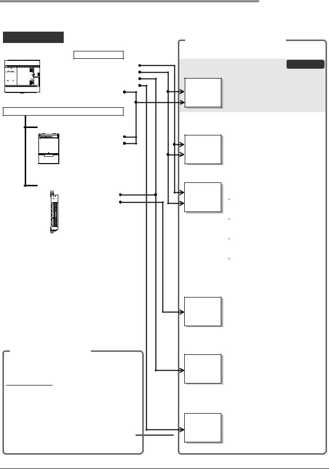
FX3S Series Programmable Controllers |
1 Introduction |
User's Manual - Hardware Edition |
1.1 Introduction of Manuals |
|
|
1.1.2Manual organization and position of this manual
This manual describes detail on the hardware, including the system configuration, installation and wiring. The instructions, communication control, analog control and positioning control are explained in separate manuals. Refer to the manuals as needed.
FX3S Series |
|
Manual for each use (separate volume) |
|
||
|
|
|
|||
Main unit |
Built-in functions |
Refer to the manual for each purpose of use. |
|||
|
|
|
|||
|
• Sequence instructions |
User's Manual - Hardware Edition |
This manual |
||
|
• High-speed counter |
JY997D48601 (Model: FX3S-HW-E) |
|
||
|
• PID instruction |
|
Details of hardware, including |
||
|
• Positioning instructions |
FX3S |
|||
|
input/output specifications, wiring, |
||||
|
• Built-in analog |
separate |
|||
|
installation and maintenance of PLC |
||||
|
|
manual |
|||
|
|
main unit |
|
||
|
|
|
|
||
Additional options |
|
|
|
||
Options |
|
Programming Manual - Basic & Applied Instruction |
|||
|
JY997D16601 (Model: FX-P3-E) |
|
|||
|
• Display module |
FX3S/FX3G/FX3GC/ |
Details of sequence program, |
||
|
• Memory cassette |
including basic and applied |
|||
|
|
FX3U/FX3UC |
instructions and various devices |
||
|
|
separate manual |
|||
|
|
The manuals for FX3S Series will be |
|||
|
|
|
|||
|
|
|
available in or after May, 2013. |
||
|
|
Structured Programming Manual |
|
||
Expansion boards, Special adapters |
FX |
For details on structured programming, |
|||
|
• Analog |
refer to the following manual. |
|||
|
separate |
||||
|
• Communication |
MELSEC-Q/L/F Structured |
|||
|
manual |
||||
|
Programming Manual (Fundamentals) |
||||
|
|
||||
|
|
|
|||
|
|
|
SH-080782 (Model: Q/FX-KP-KI-E) |
||
|
|
|
FXCPU Structured Programming |
||
|
|
|
Manual [Device & Common] |
||
|
|
|
JY997D26001 (Model: FX-KP-DK-E) |
||
|
|
|
FXCPU Structured Programming |
||
|
|
|
Manual [Basic & Applied instruction] |
||
|
|
|
JY997D34701 (Model: FX-KP-SM-E) |
||
|
|
|
FXCPU Structured Programming |
||
|
|
|
Manual [Application Functions] |
||
|
|
|
JY997D34801 (Model: FX-KP-OK-E) |
||
|
|
User's Manual - Data Communication Edition |
|||
|
|
JY997D16901 (Model: FX-U-COMMU-E) |
|
||
|
|
FX |
Details of N:N Network, parallel link, |
||
|
|
computer link, non-protocol |
|||
|
|
separate |
|||
|
|
communication and programming |
|||
|
|
manual |
communication |
|
|
|
|
|
The manuals for FX3S Series will be |
||
|
|
|
available in or after May, 2013. |
||
|
|
User's Manual - Analog Control Edition |
|
||
Manuals supplied with product |
JY997D16701 (Model: FX3U-U-ANALOG-E) |
||||
|
Details of analog expansion boards |
||||
Each product comes with the installation manual or |
FX3S/FX3G/FX3GC/ |
||||
and analog special adapters |
|||||
the User's Manual. |
|
FX3U/FX3UC |
The manuals for FX3S Series will be |
||
Installation manual |
|
separate manual |
|||
|
|
available in or after May, 2013. |
|||
The part names, installation procedures and |
|
|
|
||
specifications are shown. |
|
User's Manual - Positioning Control Edition |
|||
As for the functions and program examples, refer to |
|||||
JY997D16801 (Model: FX3U-U-POS-E) |
|
||||
the separate User's Manual - Edition). |
|
||||
|
Details of wiring, instructions and |
||||
User's manual |
|
FX3S/FX3G/FX3GC/ |
|||
|
operations of positioning functions in |
||||
The procedures for wiring and installing, specifications |
FX3U/FX3UC |
PLC main unit |
|
||
and functions are explained. |
separate manual |
The manuals for FX3S Series will be |
|||
|
|||||
|
|
|
|||
To use some products, separate manuals may be necessary. |
|
available in or after May, 2013. |
|||
|
|
|
|||
14
FX3S Series Programmable Controllers |
1 Introduction |
User's Manual - Hardware Edition |
1.1 Introduction of Manuals |
|
|
1.1.3List of manuals
FX3S Series PLC main units supplied only with the hardware manual. For the details of the hardware of FX3S Series, refer to this manual.
For instructions for programming and hardware information on special function devices, refer to the relevant manuals.
|
|
|
|
|
: Indispensable manuals |
|
|
|
|
|
|
|
|
: Manuals necessary for some purposes |
|||
|
|
|
|
|
: Manuals with separate volumes for details |
|||
|
|
|
|
|
|
|
|
|
|
|
Manual Name |
|
Manual |
Contents |
|
Model |
|
|
|
|
Number |
|
Code |
|||
|
|
|
|
|
|
|||
Manuals for PLC main unit |
|
|
|
|
|
|||
FX3S PLC main unit |
|
|
|
|
|
|||
|
|
|
|
|
|
|
||
|
Supplied |
|
|
|
Extractions of descriptions of input/output specifications, |
|
||
|
|
|
|
wiring and installation of FX3S Series PLC main unit from |
|
|||
|
with |
FX3S Series Hardware Manual |
JY997D48301 |
- |
||||
FX3S Series User's Manual - Hardware Edition. |
|
|||||||
|
product |
|
|
|
For the detailed explanation, refer to this manual. |
|
|
|
|
|
|
|
|
|
|
||
|
|
|
|
|
|
|
||
|
Supplied |
|
|
|
Extractions of descriptions of input/output specifications, |
|
||
|
FX3S-30M/E-2AD |
|
|
wiring and installation of FX3S-30M/E-2AD PLC main |
|
|||
|
with |
Hardware Manual |
|
JY997D51701 |
unit from FX3S Series User's Manual - Hardware Edition. |
- |
||
|
product |
|
|
|
For the detailed explanation, refer to this manual. |
|
|
|
|
|
|
|
|
|
|
||
|
|
|
|
|
|
|
||
|
Additional |
FX3S Series User's Manual |
|
Details of hardware of FX3S Series PLC main unit, |
|
|||
|
JY997D48601 |
including input/output specifications, wiring, installation |
09R535 |
|||||
|
Manual |
- Hardware Edition (this manual) |
|
and maintenance. |
|
|
||
|
|
|
|
|
|
|
||
|
|
|
|
|
|
|
|
|
|
Programming |
|
|
|
|
|
|
|
|
|
|
|
|
|
|||
|
Additional |
FX3S/FX3G/FX3GC/FX3U/FX3UC |
|
Details of sequence programming for FX3S Series, |
|
|||
|
Series Programming Manual - |
JY997D16601 |
including explanation for basic instructions, |
applied |
09R517 |
|||
|
Manual |
Basic & Applied Instruction Edition |
|
instructions and various devices. |
|
|
||
|
|
|
|
|
||||
|
|
|
|
|
|
|
||
|
Additional |
MELSEC-Q/L/F |
|
|
Programming methods, specifications, functions, etc. |
|
||
|
Manual |
Structured Programming Manual |
SH-080782 |
required to create structured programs. |
|
13JW06 |
||
|
|
(Fundamentals) |
|
|
|
|
|
|
|
Additional |
FX CPU |
|
|
Devices, parameters, etc. provided in structured projects |
|
||
|
Manual |
Structured Programming |
Manual |
JY997D26001 |
of GX Works2. |
|
09R925 |
|
|
|
[Device & Common] |
|
|
|
|
|
|
|
Additional |
FX CPU |
|
|
Sequence instructions provided in structured projects of |
|
||
|
Structured Programming |
Manual |
JY997D34701 |
09R926 |
||||
|
Manual |
[Basic & Applied Instruction] |
|
GX Works2. |
|
|
||
|
|
|
|
|
|
|||
|
|
|
|
|
|
|
||
|
Additional |
FX CPU |
|
|
Application functions provided in structured projects of |
|
||
|
Manual |
Structured Programming |
Manual |
JY997D34801 |
GX Works2. |
|
09R927 |
|
|
|
[Application Functions] |
|
|
|
|
|
|
Manuals for communication control |
|
|
|
|
|
|||
Common |
|
|
|
|
|
|
||
|
|
|
|
|
|
|
||
|
Additional |
FX Series User's Manual |
|
|
Details of N:N Network, parallel link, computer link and |
|
||
|
|
JY997D16901 |
non-protocol communication (RS instruction and RS2 |
09R715 |
||||
|
Manual |
- Data Communication Edition |
|
instruction). |
|
|
||
|
|
|
|
|
|
|
||
|
|
|
|
|
|
|
||
|
|
FX3S/FX3G/FX3GC/FX3U/FX3UC |
|
|
|
|
||
|
Additional |
Series User's Manual |
|
JY997D26201 |
Details on MODBUS serial communication in FX3S/FX3G/ |
09R626 |
||
|
Manual |
- MODBUS Serial Communication |
|
FX3GC/FX3U/FX3UC PLCs. |
|
|
||
|
|
Edition |
|
|
|
|
|
|
|
|
|
|
|
|
|
|
|
|
Ethernet |
|
|
|
|
|
|
|
When using each product, refer also to the User's Manual - Hardware Edition for the PLC main unit to be installed. |
|
|
||||||
|
|
|
|
|
|
|
|
|
|
Supplied |
|
|
|
Describes installation and specifications for the |
FX3U- |
|
|
|
FX3U-ENET-ADP |
|
|
ENET-ADP Ethernet communication special adapter |
|
|||
|
with |
Installation Manual |
|
JY997D47401 |
extracted from the FX3U-ENET-ADP User's Manual. |
- |
||
|
product |
|
|
|
When using, refer to FX3U-ENET-ADP User's Manual. |
|
||
|
|
|
|
|
|
|||
|
|
|
|
|
|
|
||
|
Additional |
FX3U-ENET-ADP |
|
JY997D45801 |
Describes FX3U-ENET-ADP Ethernet communication |
09R725 |
||
|
Manual |
User's Manual |
|
|
special adapter details. |
|
|
|
1 Introduction
2 PartNamesFeaturesand
3 IntroductionProduct
4 Specifications
5
VersionPeripheralDevices
and
6 ConfigurationSystem
7 Installation
8
PreparationPowerWiring
andSupply
9 InputWiring
10
HighCounters
Speed-
15

FX3S Series Programmable Controllers |
|
|
1 Introduction |
|
User's Manual - Hardware Edition |
|
|
1.1 Introduction of Manuals |
|
|
|
|
|
|
|
|
|
|
|
|
Manual Name |
Manual |
Contents |
Model |
|
Number |
Code |
||
|
|
|
||
|
|
|
|
|
RS-232C/RS-422/RS-485
When using each product, refer also to the User's Manual - Hardware Edition for the PLC main unit to be installed and FX Series User's Manual - Data Communication Edition. For the MODBUS communication, refer to the FX3S/FX3G/FX3GC/FX3U/FX3UC Series User's Manual - MODBUS Serial Communication Edition.
|
Supplied |
FX3G-232-BD |
|
Procedures for handling the RS-232C communication |
|
|
with |
Installation Manual |
JY997D32001 |
special adapter. |
- |
|
product |
|
|
|
|
|
Supplied |
FX3U-232ADP-MB |
|
Procedures for handling the RS-232C communication |
|
|
with |
Installation Manual |
JY997D26401 |
special adapter. |
- |
|
product |
|
|
|
|
|
Supplied |
FX3U-232ADP |
|
Procedures for handling the RS-232C communication |
|
|
with |
JY997D13701 |
- |
||
|
product |
Installation Manual |
|
special adapter. |
|
|
|
|
|
|
|
|
|
|
|
|
|
|
Supplied |
FX3G-422-BD |
|
Procedures for handling the RS-422 communication |
|
|
with |
Installation Manual |
JY997D32101 |
expansion board. |
- |
|
product |
|
|
|
|
|
Supplied |
FX3G-485-BD |
|
Procedures for handling the RS-485 communication |
|
|
with |
Installation Manual |
JY997D32201 |
expansion board. |
- |
|
product |
|
|
|
|
|
Supplied |
FX3G-485-BD-RJ |
|
Procedures for handling the RS-485 communication |
|
|
with |
Installation Manual |
JY997D51501 |
expansion board. |
- |
|
product |
|
|
|
|
|
Supplied |
FX3U-485ADP-MB |
|
Procedures for handling the RS-485 communication |
|
|
with |
Installation Manual |
JY997D26301 |
special adapter. |
- |
|
product |
|
|
|
|
|
Supplied |
FX3U-485ADP |
|
Procedures for handling the RS-485 communication |
|
|
with |
JY997D13801 |
- |
||
|
product |
Installation Manual |
|
special adapter. |
|
|
|
|
|
|
|
|
|
|
|
|
|
|
Supplied |
FX-485PC-IF |
|
Procedures for handling the RS-232C/RS-485 conversion |
|
|
with |
Hardware Manual |
JY992D81801 |
interface. |
- |
|
product |
|
|
|
|
Manuals for analog/temperature control |
|
|
|
||
Common |
|
|
|
|
|
|
|
|
|
|
|
|
Additional |
FX3S/FX3G/FX3GC/FX3U/FX3UC |
JY997D16701 |
Details of analog special function block (FX3U-4AD, |
09R619 |
|
Manual |
Series User's Manual |
FX3U-4DA, FX3UC-4AD), analog special adapter (FX3U- |
||
|
|
- Analog Control Edition |
|
***-**-ADP) and analog expansion board (FX3G-***-BD). |
|
Analog input and temperature input
When using each product, refer to the User's Manual - Hardware Edition for the PLC main unit to be installed and FX3S/FX3G/FX3GC/ FX3U/FX3UC Series User's Manual - Analog Control Edition.
|
Supplied |
FX3G-2AD-BD |
|
Procedures for handling the 2-ch analog input expansion |
|
|
with |
JY997D33501 |
- |
||
|
product |
Installation Manual |
|
board. |
|
|
|
|
|
|
|
|
|
|
|
|
|
|
Supplied |
FX3U-4AD-ADP |
|
Procedures for handling the 4-ch analog input special |
|
|
with |
User's Manual |
JY997D13901 |
adapter. |
- |
|
product |
|
|
|
|
|
Supplied |
FX3U-4AD-PT-ADP |
|
Procedures for handling the 4-ch Pt100 temperature |
|
|
with |
JY997D14701 |
- |
||
|
product |
User's Manual |
|
sensor input special adapter. |
|
|
|
|
|
|
|
|
|
|
|
|
|
|
Supplied |
FX3U-4AD-PTW-ADP |
|
Procedures for handling the 4-ch Pt100 temperature |
|
|
with |
User's Manual |
JY997D29101 |
sensor input special adapter. |
- |
|
product |
|
|
|
|
|
Supplied |
FX3U-4AD-PNK-ADP |
|
Procedures for handling the 4-ch Pt1000/Ni1000 |
|
|
with |
User's Manual |
JY997D29201 |
temperature sensor input special adapter. |
- |
|
product |
|
|
|
|
|
Supplied |
FX3U-4AD-TC-ADP |
|
Procedures for handling the 4-ch thermocouple input |
|
|
with |
User's Manual |
JY997D14801 |
special adapter. |
- |
|
product |
|
|
|
|
16

FX3S Series Programmable Controllers |
|
|
1 Introduction |
|
User's Manual - Hardware Edition |
|
|
1.1 Introduction of Manuals |
|
|
|
|
|
|
|
|
|
|
|
|
Manual Name |
Manual |
Contents |
Model |
|
Number |
Code |
||
|
|
|
||
|
|
|
|
|
Analog output
When using each product, refer to the User's Manual - Hardware Edition for the PLC main unit to be installed and FX3S/FX3G/FX3GC/ FX3U/FX3UC Series User's Manual - Analog Control Edition.
|
Supplied |
FX3G-1DA-BD |
|
Procedures for handling the 1-ch analog output expansion |
|
|
with |
Installation Manual |
JY997D33601 |
board. |
- |
|
product |
|
|
|
|
|
Supplied |
FX3U-4DA-ADP |
|
Procedures for handling the 4-ch analog output special |
|
|
with |
User's Manual |
JY997D14001 |
adapter. |
- |
|
product |
|
|
|
|
Analog input/output
When using each product, refer to the User's Manual - Hardware Edition for the PLC main unit to be installed and FX3S/FX3G/FX3GC/ FX3U/FX3UC Series User's Manual - Analog Control Edition.
|
Supplied |
FX3U-3A-ADP |
|
Procedures for handling the 2-ch analog input and 1-ch |
|
|
|
with |
User's Manual |
JY997D35601 |
analog output special adapter. |
- |
|
|
product |
|
|
|
|
|
Manuals for positioning control |
|
|
|
|
||
Common |
|
|
|
|
|
|
|
|
|
|
|
|
|
|
Additional |
FX3S/FX3G/FX3GC/FX3U/FX3UC |
|
Details of positioning functions of FX3S/FX3G/FX3GC/ |
|
|
|
Series User's Manual |
JY997D16801 |
09R620 |
|||
|
Manual |
- Positioning Control Edition |
|
FX3U/FX3UC Series. |
|
|
|
|
|
|
|
|
|
|
|
|
|
|
|
|
Manuals for FX-30P |
|
|
|
|
||
|
Supplied |
FX-30P |
JY997D34201 |
Describes FX-30P specification extracted from the FX- |
- |
|
|
with |
Installation Manual |
30P Operation manual. |
|||
|
product |
|
For details, refer to FX-30P Operation manual. |
|
||
|
|
|
|
|||
|
|
|
|
|
|
|
|
Additional |
FX-30P |
JY997D34401 |
Describes Handy Programming Panel FX-30P details. |
09R924 |
|
Manual |
Operation Manual |
|||||
|
|
|
|
|
|
|
Other manuals |
|
|
|
|
||
When using each product, refer also to the User's Manual - Hardware Edition for the PLC main unit to be installed. |
|
|||||
|
|
|
|
|
||
Input extension |
|
|
|
|
||
|
|
|
|
|
|
|
|
Supplied |
FX3G-4EX-BD |
|
Procedures for handling the 4 points input expansion |
|
|
|
with |
User's Manual |
JY997D51301 |
board. |
|
- |
|
product |
|
|
|
|
|
|
Output extension |
|
|
|
|
|
|
|
|
|
|
|
|
|
Supplied |
FX3G-2EYT-BD |
|
Procedures for handling the 2 points transistor output |
|
|
|
with |
JY997D51401 |
- |
|||
|
product |
User's Manual |
|
expansion board. |
|
|
|
|
|
|
|
|
|
|
|
|
|
|
|
|
|
Variable analog potentiometers |
|
|
|
|
|
|
|
|
|
|
|
|
|
|
|
|
Procedures for handling the 8-ch variable analog |
|
|
|
Supplied |
FX3G-8AV-BD |
JY997D33701 |
potentiometers expansion board. |
- |
|
|
with |
Installation Manual |
When using, refer to |
FX3S/FX3G/FX3GC/FX3U/FX3UC |
||
|
product |
|
Series Programming Manual -Basic & Applied Instruction |
|
||
|
|
|
|
|||
|
|
|
|
Edition. |
|
|
|
|
|
|
|
|
|
|
Connector |
conversion |
|
|
|
|
|
|
|
|
|
|
|
|
Supplied |
FX3S-CNV-ADP |
JY997D48801 |
Procedures for handling the conversion function |
- |
|
|
with |
Installation Manual |
expansion adapter |
for connectors for connecting |
||
|
product |
|
communication and analog special adapters. |
|
||
|
|
|
|
|||
|
|
|
|
|
|
|
|
Display module |
|
|
|
|
|
|
|
|
|
|
|
|
|
Supplied |
FX3S-5DM |
|
Procedures for mounting and handling the display |
|
|
|
with |
JY997D51601 |
- |
|||
|
product |
Installation Manual |
|
module. |
|
|
|
|
|
|
|
|
|
|
|
|
|
|
|
|
|
Memory cassette |
|
|
|
|
|
|
|
|
|
|
|
|
|
Supplied |
FX3G-EEPROM-32L |
|
Specifications and operating procedures of the memory |
|
|
|
with |
Installation Manual |
JY997D32401 |
cassette. |
|
- |
|
product |
|
|
|
|
|
1 Introduction
2 PartNamesFeaturesand
3 IntroductionProduct
4 Specifications
5
VersionPeripheralDevices
and
6 ConfigurationSystem
7 Installation
8
PreparationPowerWiring
andSupply
9 InputWiring
10
HighCounters
Speed-
17

FX3S Series Programmable Controllers |
1 Introduction |
User's Manual - Hardware Edition |
1.2 Generic Names and Abbreviations Used in Manuals |
|
|
1.2Generic Names and Abbreviations Used in Manuals
Abbreviation/generic name |
Description |
|
PLCs |
|
|
FX3S Series |
Generic name for FX3S Series PLCs |
|
|
|
|
FX3G Series |
Generic name for FX3G Series PLCs |
|
|
|
|
FX3U Series |
Generic name for FX3U Series PLCs |
|
|
|
|
FX3S PLCs or main units |
Abbreviation of FX3S Series PLC main units |
|
|
|
|
|
Generic name for the following models |
|
Expansion boards |
FX3G-4EX-BD, FX3G-2EYT-BD, FX3G-232-BD, FX3G-422-BD, FX3G-485-BD, FX3G-485-BD-RJ, |
|
|
FX3G-2AD-BD, FX3G-1DA-BD, FX3G-8AV-BD |
|
|
|
|
Special adapters |
Generic name for communication special adapters and analog special adapters |
|
|
|
|
Communication special |
Generic name for the following models |
|
adapters |
FX3U-232ADP(-MB), FX3U-485ADP(-MB), FX3U-ENET-ADP |
|
|
|
|
|
Generic name for the following models |
|
Analog special adapters |
FX3U-4AD-ADP, FX3U-4DA-ADP, FX3U-3A-ADP, FX3U-4AD-PT-ADP, FX3U-4AD-PTW-ADP, |
|
|
FX3U-4AD-PNK-ADP, FX3U-4AD-TC-ADP |
|
|
|
|
Display module |
Generic name for the following model |
|
FX3S-5DM |
||
|
||
|
|
|
Memory cassettes |
Generic name for the following model |
|
FX3G-EEPROM-32L |
||
|
||
|
|
|
Peripheral devices |
Generic name for programming software, handy programming panel (HPP) and indicator |
|
|
|
|
Programming tool |
Generic name for programming software and handy programming panel (HPP) |
|
|
|
|
Programming software |
Generic name for GX Works2 and GX Developer |
|
|
|
|
GX Works2 |
Abbreviation of programming software package SWDNC-GXW2-E |
|
|
|
|
GX Developer |
Abbreviation of programming software package SWD5C-GPPW-E |
|
|
|
|
Handy programming panels |
Generic name for the following model |
|
(HPP) |
FX-30P |
|
|
|
|
RS-232C/RS-422 converters |
Generic name for the following model |
|
FX-232AWC-H |
||
|
||
|
|
|
RS-232C/RS-485 converters |
Abbreviation of FX-485PC-IF |
|
|
|
|
Indicators |
|
|
GOT1000 Series |
Generic name for GT16, GT15, GT14, GT11 and GT10 |
|
|
|
|
GOT-900 Series |
Generic name for GOT-A900 Series and GOT-F900 Series |
|
|
|
|
GOT-A900 Series |
Generic name for GOT-A900 Series |
|
|
|
|
GOT-F900 Series |
Generic name for GOT-F900 Series |
|
|
|
|
Manuals |
|
|
FX3S Hardware Edition |
Abbreviation of FX3S Series User's Manual - Hardware Edition |
|
|
|
|
Programming manual |
Abbreviation of FX3S/FX3G/FX3GC/FX3U/FX3UC Series Programming Manual |
|
- Basic & Applied Instruction Edition |
||
|
||
|
|
|
Data Communication Edition |
Abbreviation of FX Series User's Manual - Data Communication Edition |
|
|
|
|
MODBUS Serial |
Abbreviation of FX3S/FX3G/FX3GC/FX3U/FX3UC Series User's Manual |
|
Communication Edition |
- MODBUS Serial Communication Edition |
|
|
|
|
Analog Control Edition |
Abbreviation of FX3S/FX3G/FX3GC/FX3U/FX3UC Series User's Manual - Analog Control Edition |
|
|
|
|
Positioning Control Edition |
Abbreviation of FX3S/FX3G/FX3GC/FX3U/FX3UC Series User's Manual - Positioning Control Edition |
|
|
|
|
ENET-ADP User's Manual |
Abbreviation of FX3U-ENET-ADP User's Manual |
|
|
|
18

FX3S Series Programmable Controllers |
2 Features and Part Names |
||
User's Manual - Hardware Edition |
2.1 Major Features |
||
|
|
|
|
|
|
|
|
|
|
|
|
2.Features and Part Names
2.1Major Features
1.Basic functions
[Up to 30 input/output points]
Main units are available in models of 10, 14, 20 and 30 total input/output points.
[Memory capacity]
The PLC has a 16 K-step EEPROM memory. (Program capacity is 4 K-steps.)
[Built-in USB port]
The PLC has a built-in USB port for the programming communication function to enable high-speed communication at 12 Mbps.
[Built-in RUN/STOP switch]
The PLC can be started and stopped with the built-in switch.
RUN and STOP commands can be given to the PLC through a general-purpose input terminal or peripheral device.
[Built-in Variable analog potentiometers]
(except FX3S-30M/E-2AD)
The PLC has two built-in variable analog potentiometers available for adjusting the timer set time.
Up to 8 points can be added by using the optional analog potentiometer expansion board.
[Built-in analog inputs]
(only FX3S-30M/E-2AD)
The PLC has two built-in analog inputs available for voltage input.
Additional analog input points can be added by using an optional expansion board or special adapter.
[Writing during RUN]
The programming software for personal computer enables you to modify the program while the PLC is running.
[Built-in clock function]
The PLC has a clock function to control the time.
[Programming tool]
Use a version of a programming tool supporting the FX3S.
Refer to Chapter 5.
[Remote debugging of program]
Programming software enables you to remotely transfer programs and monitor PLC operation through a modem connected to the RS-232C expansion board or the RS-232C communication special adapter.
2.Input/output high-speed processing functions of main unit
[High-speed counter function]
-1-phase 60 kHz × 2 points + 10 kHz × 4 points
-2-phase 30 kHz × 1 points + 5 kHz × 1 point
Refer to Chapter 10 and Programming Manual.
[Pulse catch function]
Signals with short ON width or OFF width can be captured without a complicated program.
Refer to Chapter 9 and Programming Manual.
Input terminal |
Signal ON/OFF width |
X000, X001 |
10 s |
|
|
X002 to X005 |
50 s |
|
|
[Input interruption function]
The PLC can process interruption routines with higher priority using external signals whose minimum ON duration or OFF duration is 10 s (X000, X001) or 50 s (X002 to X005).
(The timer interruption function is also provided.)
Refer to Chapter 9 and Programming Manual.
[Pulse output function]
When output terminals in the transistor output type main unit are used, pulses of up to 100 kHz can be output simultaneously to 2 axes (Y000 and Y001).
Using a number of instructions programming is simplified.
Refer to Positioning Control Edition.
[Various positioning instructions]
Instruction |
|
Description |
|
||
DSZR |
Mechanical |
zero return |
instruction |
with |
|
DOG search function. |
|
|
|||
|
|
|
|||
|
|
||||
|
Instruction to read the current value from |
||||
ABS |
our servo amplifier with absolute position |
||||
|
(ABS) detecting function. |
|
|
||
|
|
||||
DRVI |
Positioning (relative positioning) to specify |
||||
the movement from the current position. |
|||||
|
|||||
|
|
|
|
|
|
|
Positioning |
(absolute |
positioning) |
to |
|
DRVA |
specify the target position based on the |
||||
|
current value 0. |
|
|
||
|
|
||||
PLSV |
Instruction to change the pulse train output |
||||
frequency. |
|
|
|
||
|
|
|
|
||
|
|
|
|
|
|
Refer to Positioning Control Edition.
1 Introduction
2 PartNamesFeaturesand
3 IntroductionProduct
4 Specifications
5
VersionPeripheralDevices
and
6 ConfigurationSystem
7 Installation
8
PreparationPowerWiring
andSupply
9 InputWiring
10
HighCounters
Speed-
19

FX3S Series Programmable Controllers |
2 Features and Part Names |
User's Manual - Hardware Edition |
2.1 Major Features |
|
|
3.Display functions (display module) (Supported in Ver. 1.20 or later)
FX3S-5DM Display Module (option) can be installed on the PLC.
[Monitor/test function]
Devices can be monitored and tested by operating the buttons on the display module. The button operations can be inhibited by the user program.
[Other functions]
On the display module, you can set the time and display error codes.
Refer to Chapter 16.
4.Communication and network functions
The expansion board and special adapter for each communication function can be connected.
Refer to Data Communication Edition.Refer to MODBUS Serial
Communication Edition.Refer to ENET-ADP User's Manual.
[Kinds of communication functions]
•Programming communication (RS-232C/RS-422/USB)
•N:N Network
•Parallel link
•Computer link
•Inverter communication
•Non-protocol communication (RS-232C/RS-485)
•MODBUS communication
•Ethernet
5.Analog functions
The expansion board and special adapter for each analog function are connected.
Refer to Analog Control Edition.
[Kinds of analog functions]
•Voltage/current input
•Voltage/current output
•Temperature sensor input (thermocouple and platinum resistance thermometer sensor)
20
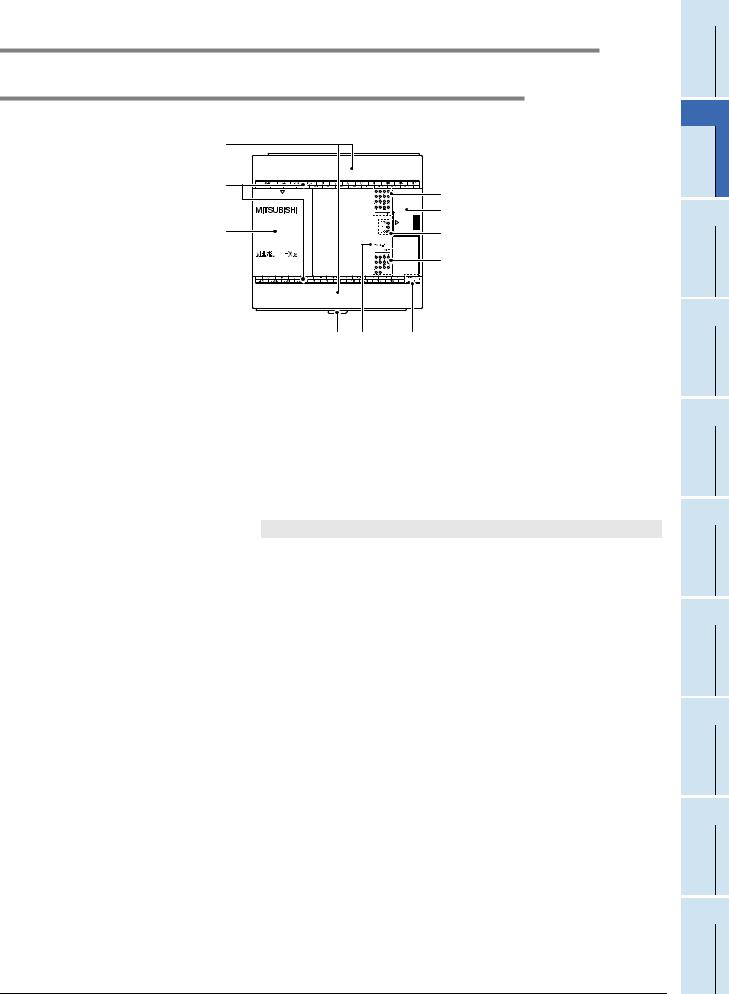
FX3S Series Programmable Controllers |
2 Features and Part Names |
User's Manual - Hardware Edition |
2.2 Names and Functions of Parts |
|
|
2.2Names and Functions of Parts
2.2.1Front Panel
Factory default configuration (standard)
[3] |
|
|
[2] |
|
[4] |
|
|
|
|
|
[5] |
[1] |
|
[6] |
|
|
[7] |
[10] |
[9] |
[8] |
[1] |
Top cover |
Mount the expansion board, display module and memory cassette under this cover. |
||||
[2] |
Terminal names |
The signal names for power supply, input and output terminals are shown. |
||||
[3] |
Terminal block covers |
The covers can be opened for wiring. |
||||
|
|
Keep the covers closed while the PLC is running (the unit power is on). |
||||
[4] |
Input display LEDs (red) |
When an input terminal (X000 or more) is turned on, the corresponding LED lights. |
||||
[5] |
Peripheral device connecting |
The peripheral device connector, variable analog potentiometers, analog inputs and RUN/ |
||||
|
connector cover |
STOP switch are located under this cover. |
||||
[6] |
Operation status display LEDs |
The operation status of the PLC can be checked with the LEDs. |
||||
|
|
The LEDs turn off, light and flash according to the following table. |
||||
|
|
|
|
For details on the operation status, refer to Section 14.5. |
||
|
|
|
|
|
|
|
|
|
|
LED name |
Display color |
Description |
|
|
|
|
|
|
|
|
|
|
|
POW |
Green |
ON while power is on the PLC. |
|
|
|
|
|
|
|
|
|
|
|
RUN |
Green |
ON while the PLC is running. |
|
|
|
|
|
|
|
|
|
|
|
ERR |
Red |
Flashing when a program error occurs. |
|
|
|
|
|
|
|
|
|
|
|
Red |
Lights when a CPU error occurs. |
||
|
|
|
|
|||
[7] |
Output display LEDs (red) |
|
|
|
|
|
When an output terminal (Y000 or more) is turned on, the corresponding LED lights. |
||||||
[8] |
The year and month of production |
The year and month of production of the main unit is indicated. |
||||
|
|
|
|
|
For details on the year and month of production, |
|
|
|
|
|
|
refer to Subsection 5.1.1. |
|
[9] |
Model name (abbreviation) |
The model name of the main unit is indicated. |
||||
|
|
Check the nameplate on the right side for the model name. |
||||
[10] |
DIN rail mounting hooks |
The main unit can be installed on DIN46277 rail (35 mm (1.38") wide). |
||||
1 Introduction
2 PartNamesFeaturesand
3 IntroductionProduct
4 Specifications
5
VersionPeripheralDevices
and
6 ConfigurationSystem
7 Installation
8
PreparationPowerWiring
andSupply
9 InputWiring
10
HighCounters
Speed-
21
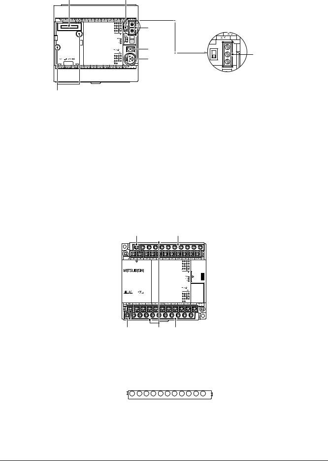
FX3S Series Programmable Controllers |
2 Features and Part Names |
User's Manual - Hardware Edition |
2.2 Names and Functions of Parts |
|
|
When the top covers are open
[1] |
[2] |
|
[3] |
|
[5] |
|
[6] |
[7] |
|
[In the case of FX3S-30M□/E□-2AD]
[4]
[1] Optional equipment connector These holes are designed to secure the expansion board, display module and memory cassette with screws.
[2] |
RUN/STOP switch |
To stop writing (batch) of the sequence program or operation, set the switch to STOP (slide |
|
|
it downward). |
|
|
To start operation (run the machine), set it to RUN (slide it upward). |
[3] |
Variable analog potentiometers |
Two variable analog potentiometers are built in. |
|
(except FX3S-30M/E-2AD) |
Upper side: VR1, Lower side: VR2 |
[4] Analog input terminal block |
Two analog inputs are built in. |
|
|
(only FX3S-30M/E-2AD) |
These terminals are for wiring the analog inputs. |
[5] |
Peripheral device connecting |
Connect a programming tool (PC) to program a sequence. |
|
connector (USB) |
For details on applicable peripheral devices, refer to Chapter 5. |
[6] |
Peripheral device connecting |
Connect a programming tool to program a sequence. |
|
connector (RS-422) |
For details on applicable peripheral devices, refer to Chapter 5. |
[7]Optional equipment connecting These holes are designed to secure the expansion board and memory cassette with screws. screw holes (2 places)
When the terminal block covers are open
[1] |
|
[2] |
[5] |
[4] |
[3] |
[1] |
Power supply terminals |
Connect the power supply to the main unit. |
|||
[2] |
Input (X) terminals |
Wire switches and sensors to the terminals. |
|||
[3] |
Output (Y) terminals |
Wire loads (contactors, solenoid valves, etc.) to be driven to the terminals. |
|||
[4] |
Terminal cover |
A protective terminal cover (refer to the following drawing) is fitted to the lower stage of each |
|||
|
|
terminal block. |
|||
|
|
The cover prevents fingers from touching terminals, thereby improving safety. |
|||
[5] Service power supply terminals |
|
|
|
||
|
|
|
|
||
|
|
|
|
||
|
|
|
|||
Wire sensors or other external equipment to these terminals when the service power supply |
|||||
|
(only AC power type) |
(24 V DC) is used for such equipment. |
|||
22
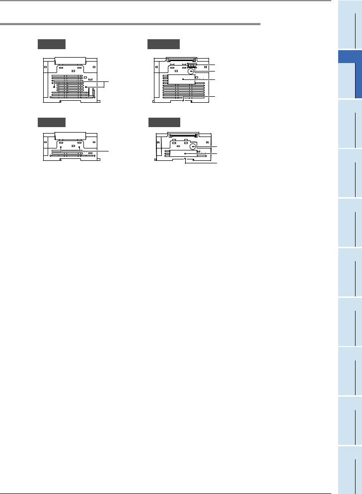
FX3S Series Programmable Controllers |
2 Features and Part Names |
|
User's Manual - Hardware Edition |
2.2 Names and Functions of Parts |
|
2.2.2 Sides |
|
|
[AC Power Type] |
|
|
Left side |
Right side |
|
|
[2] |
|
|
[3] |
|
[1] |
[4] |
|
|
||
|
[5] |
|
[DC power type] |
|
|
Left side |
Right side |
|
[1] |
[3] |
|
[4] |
||
|
||
|
[5] |
[1]Connector conversion adapter These holes are designed to secure the connector conversion adapter with screws. connecting screw holes (2 places)
[2] Analog input terminal block |
Two analog inputs are built in. |
|
|
(only FX3S-30M/E-2AD) |
These terminals are for wiring the analog inputs. |
[3] |
Label of authenticity |
The label of authenticity is affixed to the right side of the product and indicates that the |
|
|
product is genuine. |
|
|
Product without the label or nameplate is not covered by the warranty. |
[4] |
Nameplate |
The product model name, serial number and power supply specifications are shown. |
|
|
For details on the manufacturer's serial number, |
|
|
refer to Subsection 5.1.1. |
[5] |
DIN rail mounting groove |
The unit can be installed on DIN46277 rail (35 mm (1.38") wide). |
1 Introduction
2 PartNamesFeaturesand
3 IntroductionProduct
4 Specifications
5
VersionPeripheralDevices
and
6 ConfigurationSystem
7 Installation
8
PreparationPowerWiring
andSupply
9 InputWiring
10
HighCounters
Speed-
23

FX3S Series Programmable Controllers |
3 Introduction of Products |
||
User's Manual - Hardware Edition |
3.1 List of Products and Interpretation of Model Names |
||
|
|
|
|
|
|
|
|
|
|
|
|
3.Introduction of Products
3.1List of Products and Interpretation of Model Names
The following system configuration is classified into product groups A to F in the product introduction sections given below.
B |
Expansion boards |
E Display module |
F Memory cassette |
|
|
|
|
|
|
|
|
|
|
• FX3S-5DM |
|
|
|
Input |
|
Output |
|
|
|
||
|
|
|
|
|
|
|
|
|||
• FX3G-4EX-BD |
|
• FX3G-2EYT-BD |
|
|
|
|
||||
|
|
|
|
|
||||||
|
|
|
|
|
|
|
|
|
|
|
Communication |
|
Analog |
|
|
|
|
||||
• FX3G-232-BD |
|
• FX3G-2AD-BD |
|
|
|
|
||||
• FX3G-422-BD |
|
• FX3G-1DA-BD |
|
|
|
|
||||
• FX3G-485-BD |
|
|
|
|
|
|
|
|||
|
Analog volume |
|
|
|
|
|||||
• FX3G-485-BD-RJ |
|
|
|
|
|
|||||
|
• FX3G-8AV-BD |
|
|
|
|
|||||
|
|
|
|
|
|
|
|
|
||
|
|
|
|
|
|
|
|
|
|
|
|
|
|
|
|
|
|
|
|
|
|
|
|
|
|
|
|
|
|
|
|
|
|
|
|
|
|
|
|
|
|
|
|
|
|
|
|
|
|
|
|
|
|
|
|
|
|
|
|
|
|
|
|
|
|
|
|
|
|
|
|
|
|
|
|
|
|
|
|
|
|
|
|
|
|
|
|
|
|
|
|
|
|
|
|
|
|
|
|
|
|
|
|
|
|
|
|
|
|
• FX3G-EEPROM-32L |
D |
Special adapters |
|
C |
Connector conversion adapter |
|
A |
|
Main unit |
|
|
|
|
|
• FX3S-CNV-ADP |
|
|
|
|
|
|
Analog |
|
|
|
|
Input/output |
|
||
• FX3U-4AD-ADP |
|
|
• FX3S-10MR/ES |
• FX3S-10MT/ES(S) |
|||||
• FX3U-4DA-ADP |
|
|
• FX3S-14MR/ES |
• FX3S-14MT/ES(S) |
|||||
• FX3U-3A-ADP |
|
|
• FX3S-20MR/ES |
• FX3S-20MT/ES(S) |
|||||
• FX3U-4AD-PT-ADP |
|
|
• FX3S-30MR/ES |
• FX3S-30MT/ES(S) |
|||||
• FX3U-4AD-PTW-ADP |
|
|
• FX3S-30MR/ES-2AD • FX3S-30MT/ES(S)-2AD |
||||||
• FX3U-4AD-PNK-ADP |
|
|
|||||||
|
|
• FX3S-10MR/DS |
• FX3S-10MT/DS(S) |
||||||
• FX3U-4AD-TC-ADP |
|
|
|||||||
|
|
• FX3S-14MR/DS |
• FX3S-14MT/DS(S) |
||||||
|
|
|
|
|
|||||
Communication |
|
|
|
• FX3S-20MR/DS |
• FX3S-20MT/DS(S) |
||||
• FX3U-232ADP (-MB) |
|
|
• FX3S-30MR/DS |
• FX3S-30MT/DS(S) |
|||||
• FX3U-485ADP (-MB) |
|
|
|
|
|
|
|
||
• FX3U-ENET-ADP |
|
|
|
|
|
|
|
||
24
Loading...