


Miele PW 6163, PW 6243, PW 6323, UG 6163, UG 6243 assembly instruction
...Produktgruppen 512, 592 |
|
|
Umbauund Montageanweisung |
||||
1 von 26 |
|
|
|
|
M.-Nr. 07564361 |
||
PW 6163, PW 6243, PW 6323, UG 6163, UG 6243, UG 6323 |
|
|
|
||||
x |
|
|
|
|
|
|
|
de |
Montageanweisung Unterbau- |
en |
Fitting instructions - |
|
fr |
Notice de montage de socle - |
|
|
sockel Reine-Unreine-Seite |
|
Plinth, clean-soiled side |
|
|
machine aseptique |
|
ni |
Montage-instructie sokkel |
da |
Monteringsanvisning |
|
no |
Monteringsveiledning |
|
underbygningssokkel |
|
for innbyggingssokkel |
|||||
schone-vuile zijde |
|
||||||
|
|
ren-uren side |
|
|
ren-uren-side |
||
|
|
|
|
|
|||
|
|
|
|
|
|
|
|
|
|
|
Istruzioni di montaggio base |
|
Instrucciones de montaje del |
||
sv |
Sockel till "barriärtvättmskin" |
it |
es |
zócalo del lado |
|||
lato decontaminato/ |
|
||||||
(maskin med ren/oren sida) |
|
descontaminado y |
|||||
|
|
contaminato |
|
|
|||
|
|
|
|
|
contaminado |
||
|
|
|
|
|
|
||
|
|
|
|
|
|
|
|
am |
Installation Instructions - |
|
|
|
|
|
|
|
Stand, Clean-Soiled Side |
|
|
|
|
|
|
1
02.03.2012 |
Diese Unterlagen dürfen ohne unsere Genehmigung weder vervielfältigt noch Dritten zugänglich gemacht werden. Eigentumsrechte vorbehalten. |
Produktgruppen 512, 592 |
Umbauund Montageanweisung |
2 von 26 |
M.-Nr. 07564361 |
x |
|
3
2
4
02.03.2012 |
Diese Unterlagen dürfen ohne unsere Genehmigung weder vervielfältigt noch Dritten zugänglich gemacht werden. Eigentumsrechte vorbehalten. |

Produktgruppen 512, 592 |
Umbauund Montageanweisung |
3 von 26 |
M.-Nr. 07564361 |
de
Benötigte Teile x
Anzahl |
M.-Nr. |
Benennung |
1 |
07493360 |
Montagesatz Unterbausockel UG 6163 octoblau für PW 6163 |
1 |
07493370 |
Montagesatz Unterbausockel UG 6163 edelstahl für PW 6163 |
1 |
07493380 |
Montagesatz Unterbausockel UG 6243 octoblau für PW 6243 |
1 |
07493390 |
Montagesatz Unterbausockel UG 6243 edelstahl für PW 6243 |
1 |
07493400 |
Montagesatz Unterbausockel UG 6323 octoblau für PW 6323 |
1 |
07493410 |
Montagesatz Unterbausockel UG 6323 edelstahl für PW 6323 |
1 |
06585110 |
Rohr HTEM DN 75x250 zur Verlängerung des Bodenablaufes um mind. 170 mm |
Hinweis
Diese Umbauarbeiten dürfen grundsätzlich nur von einer Elektrofachkraft (fachliche Ausbildung, Fachkenntnisse und Facherfahrungen, zeitnahe berufliche Tätigkeit) unter Berücksichtigung der gültigen Sicherheitsbestimmungen durchgeführt werden.
Für die Instandsetzung, Änderung, Prüfung und Wartung elektrischer Geräte sind die entsprechenden gesetzlichen Grundlagen, Unfallverhütungsvorschriften, die gültigen Normen, die der Sicherheit dienen, sowie die am Aufstellungsort gültigen Vorschriften der Energieversorgungsunternehmen zu beachten.
Gefahr!
Auch bei ausgeschaltetem Gerät kann Netzspannung an Bauteilen anliegen!
Deshalb ist, bevor Wartungs-, Instandsetzungsund Umbauarbeiten am Gerät durchgeführt werden, eine sichere Netztrennung von allen aktiven, spannungsführenden Leitungen sowie anschließend eine Messung der Spannungsfreiheit erforderlich!
Grundsätzlich muss eine allgemeine Sichtprüfung durchgeführt werden.
Ein nicht fachgerechter Umbau kann zum Brand führen.
Gefahr!
Verletzungsgefahr bei der Montage
•Stromschlaggefahr. Vor Wartungsund Instandsetzungsarbeiten am Gerät, alle spannungsführenden Leitungen vom Netz trennen.
•Den Sockel nur an Waschautomaten montieren, die nicht installiert sind. Deinstallation siehe GeräteGebrauchsanweisung.
•Quetschgefahr. Rutschfeste Handschuhe und Sicherheitsschuhe tragen.
•Quetschgefahr. Darauf achten, dass keine Körperteile, insbesondere Hände und Füße, unter oder zwischen die Geräte gelangen.
•Unfallgefahr. Sicherstellen, dass während der Montagearbeiten keine Personen oder Tiere in den Arbeitsbereich gelangen können.
•Verletzungsgefahr, insbesondere Verletzung der Wirbelsäule. Das Gewicht der Geräte im Verhältnis zur eigenen körperlichen Kraft beachten. Gewichtsangabe des Gerätes siehe Geräte-Gebrauchsanweisung.
Verletzungsgefahr durch fehlerhafte Montage
•Die Maschinen stets mit dem Sockel verschrauben.
•Bei der Bodenbefestigung vier Befestigungswinkel am Boden befestigen.
02.03.2012 |
Diese Unterlagen dürfen ohne unsere Genehmigung weder vervielfältigt noch Dritten zugänglich gemacht werden. Eigentumsrechte vorbehalten. |

Produktgruppen 512, 592 |
Umbauund Montageanweisung |
4 von 26 |
M.-Nr. 07564361 |
Hinweis
Die Sockel ausschließlich für folgende Miele-Geräte verwenden:
•PW 6163 (07493360, 07493370)
•PW 6243 (07493380, 07493390)
•PW 6323 (07493400, 07493410)
Hinweis
Erforderliches Werkzeug:
•Wasserwaage zum lotrechten Ausrichten des Sockels.
•Maulschlüssel Schlüsselweite 19 mm für die Schrauben 12 x 90 mm Bodenbefestigung.
•Maulschlüssel Schlüsselweite 10 mm für die Schrauben 6 x 10 mm Fußbefestigung.
•Schraubendreher Torx 20.
Hinweis
Die Montagesätze enthalten:
•2 x Fuß vormontiert
•2 x Frontblende vormontiert
•2 x Seitenverkleidung Sockel
•12 x Schrauben DM 6 x 12
•8 x Schrauben CEM 6 x 16
•1 x Hinweiszettel
•Diese Montageanweisung “Unterbausockel Reine-Unreine-Seite”, M.-Nr. 07564361.
Liste der Abbildungen:
–Abb. 1, Seitenverkleidungen und Montageklappen der Maschine abbauen
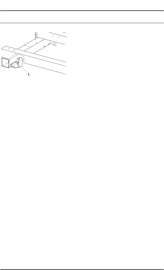
–Abb. 2, Bodenbefestigung abschrauben
–Abb. 3, Fuß anschrauben
–Abb. 4, Frontblenden und Seitenverkleidungen des Sockels montieren
–Die Maschine vom Elektronetz und gegebenenfalls vom Dampfanschluss trennen und gegen Wiedereinschalten sichern.
–Die 2 Seitenverkleidungen und 2 Montageklappen abbauen, siehe Abb. 1.
–Die Bodenbefestigungen der Maschine herausschrauben.
x
Hinweis
Gegebenenfalls vorhandene Ausgleichbleche aufheben und bei der Montage an der gleichen Position in der gleichen Anzahl wieder einsetzen.
–Den Bodenablauf abziehen.
–Die Maschine mit geeignetem Hubwerkzeug um ca. 200 mm anheben. Z.B. mit Hubwagen und tragfähigen Holzklötzen.
x
Gefahr!
Die Maschine gegen Herunterfallen sichern.
–Die 4 Bodenbefestigungen vom Grundrahmen abschrauben, siehe Abb. 2, Pos. 1.
–Die vormontierten Füße, siehe Abb. 4, Pos. 2, links und rechts unter den Grundrahmen der Maschine schieben und festschrauben.
(Je Ecke 2 Schrauben von innen und 1 Schraube von unten schrauben. Siehe Abb. 4, Pos. 3.)
02.03.2012 |
Diese Unterlagen dürfen ohne unsere Genehmigung weder vervielfältigt noch Dritten zugänglich gemacht werden. Eigentumsrechte vorbehalten. |

Produktgruppen 512, 592 |
Umbauund Montageanweisung |
5 von 26 |
M.-Nr. 07564361 |
x
Achtung!
Zur Befestigung der vormontierten Füße am Grundrahmen die neuen Schrauben DM 6 x 12 aus dem Beipack verwenden.
–Die Verbindung zwischen Abwasserstutzen der Maschine und bauseitigem Ablauf um ca. 170 mm verlängern.
–Die Maschine absenken und in der ursprünglichen Position absetzen.
–Den waagerechten Stand der Maschine in allen Richtungen überprüfen.
Gegebenenfalls waagerechten Stand der Maschine durch Einsatz von Ausgleichblechen herstellen.
–Die Schrauben zur Bodenbefestigung in den vorhandenen Dübelbohrungen der Befestigungswinkel verschrauben, siehe Abb. 3, Pos. 1.
–Die beiden Frontblenden, siehe Abb. 3, Pos. 2) vorne und hinten montieren und an den Ecken der Maschine ausrichten.
–Die Seitenverkleidungen Sockel, siehe Abb. 3, Pos. 3, einsetzen. Gegebenenfalls die Frontblenden, siehe Abb. 3, Pos. 2, nachstellen.
–Die 2 Seitenverkleidungen und 2 Montageklappen der Maschine anbauen.
–Eine elektrische Sicherheitsprüfung durchführen.
–Die Maschine an das Elektronetz und gegebenenfalls an den Dampfanschluss anschließen.
de en
Parts required x
Quantity |
Mat. no. |
Designation |
1 |
07493360 |
Fitting kit - Plinth UG 6163, octoblue, for PW 6163 |
1 |
07493370 |
Fitting kit - Plinth UG 6163, stainless steel, for PW 6163 |
1 |
07493380 |
Fitting kit - Plinth UG 6243, octoblue, for PW 6243 |
1 |
07493390 |
Fitting kit - Plinth UG 6243, stainless steel, for PW 6243 |
1 |
07493400 |
Fitting kit - Plinth UG 6323, octoblue, for PW 6323 |
1 |
07493410 |
Fitting kit - Plinth UG 6323, stainless steel, for PW 6323 |
1 |
06585110 |
Pipe HTEM DN 75 x 250 to extend floor drain outlet by at least 170 mm |
Note
This service and repair work should only be carried out by a suitably qualified electrician (with specialist training, knowledge and experience, and recent related work experience) in accordance with all appropriate local and national safety regulations.
Servicing, modification, testing and maintenance of electrical appliances should only be carried out in accordance with all appropriate legal requirements, accident prevention regulations and valid standards. All regulations of the appropriate utility supply companies and standards relating to safety (not limited to electrical safety) are to be complied with.
Danger!
Even with the machine switched off, mains voltage may be applied to some components.
Before any service work is commenced, the machine must be disconnected from the mains. Suitable measurements must be made to ensure that this is the case.
A general visual check should always be carried out.
Incorrect conversion or service work could lead to a risk of fire.
02.03.2012 |
Diese Unterlagen dürfen ohne unsere Genehmigung weder vervielfältigt noch Dritten zugänglich gemacht werden. Eigentumsrechte vorbehalten. |

Produktgruppen 512, 592 |
Umbauund Montageanweisung |
6 von 26 |
M.-Nr. 07564361 |
Danger!
Risk of injury during fitting.
•Risk of electric shock. Before any service work is commenced, the machine must be disconnected from the mains.
•Fitting can only be carried out with the washing machine or tumble dryer not installed. For deinstallation, see the appropriate operating instructions.
•Risk of crushing. Wear slip-proof working gloves and safety shoes.
•Risk of crushing. When carrying out work, ensure that parts of the body, especially the hands and feet are not positioned under or between machines.
•Risk of accident. Ensure that children or pets cannot access the work area while fitting work is being carried out.
•Risk of injury, particularly to the back. The relation of the weight of the machine to the physical strength of the technician must be taken into account. For machine weight details, see the operating instructions.
Risk of injury due to incorrect fitting.
•Always bolt the machine to the plinth.
•With floor fastening, secure all four fixing brackets.
Note
The plinths may only be used with the following Miele models:
•PW 6163 (07493360, 07493370)
•PW 6243 (07493380, 07493390)
•PW 6323 (07493400, 07493410)
Note
Tools required:
•Spirit level for plinth levelling.
•Open spanner, 19 mm, for 12 x 90 mm bolts for floor fixing.
•Open spanner, 10 mm, for 6 x 10 mm bolts for foot fixing.
•Torx screwdriver, T 20.
Note
The kits contain the following:
•2 x Foot, pre-fitted
•2 x Front plinth panel, pre-fitted
•2 x Side plinth panel
•12 x Screw, DM 6 x 12
•8 x Screw, CEM 6 x 16
•1 x Information sheet
•Fitting instructions - Plinth, clean-soiled side, Mat. no. 07564361.
List of illustrations:
–Fig. 1: Side panel and service panel removal
–Fig. 2: Floor fixing bracket removal
–Fig. 3: Foot fitting
–Fig. 4: Front plinth panel and side plinth panel fitting
02.03.2012 |
Diese Unterlagen dürfen ohne unsere Genehmigung weder vervielfältigt noch Dritten zugänglich gemacht werden. Eigentumsrechte vorbehalten. |

Produktgruppen 512, 592 |
Umbauund Montageanweisung |
7 von 26 |
M.-Nr. 07564361 |
–Disconnect the machine from the steam supply (if applicable) and electric mains, and ensure utilities cannot be switched on again in error.
–Remove the 2 side panels and 2 service panels, Fig. 1.
–Unscrew the machine floor fastening.
x
Note
If present, remove any spacer plates that may be in use and take care to note the number fitted and their positions so that they can be refitted in an identical manner.
–Disconnect the floor drain.
–Use a suitable lifting aid to raise the machine by approx. 200 mm. E.g. pallet truck and suitable wood blocks.
x
Danger!
Take suitable measures to ensure the machine cannot fall.
–Unscrew the 4 floor fixing brackets, Fig. 2, Pos. 1.
–Fit the pre-fitted feet, Fig. 4, Pos. 2, on the left and right under the machine base frame and screw them in position. (On each corner, 2 screws from the inside and 1 screw from the bottom, see Fig. 4, Pos. 3.)
x
Warning!
Use the new DM 6 x 12 screws from the accessory pack to secure the pre-fitted feet to the base frame.
–Extend the connection between the machine drain outlet and the on-site drain by approx. 170 mm.
–Lower the machine and return it to its original position.
–Check that the machine is perfectly level in all directions.
If necessary, level the machine by fitting spacer plates as appropriate.
–Fit the floor fixing bolts through the fixing brackets in the existing holes, Fig. 3, Pos. 1.
–Fit the 2 front plinth panels, Fig. 3, Pos. 2, at the front and back, and align them with the corners of the machine.
–Fit the 2 side plinth panels, Fig. 3, Pos. 3. Readjust the 2 front plinth panels if necessary, Fig. 3, Pos. 2.
–Refit the 2 side panels and 2 service panels.
–Carry out appropriate electrical safety checks.
–Reconnect the machine to the mains and the steam supply (if applicable).
en
fr
Pièces nécessaires x
Nombre |
Mat.-Nr. |
Désignation |
1 |
07493360 |
Jeu de montage du socle UG 6163 octobleu pour PW 6163 |
1 |
07493370 |
Jeu de montage du socle UG 6163 inox pour PW 6163 |
1 |
07493380 |
Jeu de montage du socle UG 6243 octobleu pour PW 6243 |
1 |
07493390 |
Jeu de montage du socle UG 6243 inox pour PW 6243 |
1 |
07493400 |
Jeu de montage du socle UG 6323 octobleu pour PW 6323 |
1 |
07493410 |
Jeu de montage du socle UG 6323 inox pour PW 6323 |
1 |
06585110 |
Tuyau HTEM DN 75x250 - rallonge de la vidange au sol de minimum 170 mm |
02.03.2012 |
Diese Unterlagen dürfen ohne unsere Genehmigung weder vervielfältigt noch Dritten zugänglich gemacht werden. Eigentumsrechte vorbehalten. |

Produktgruppen 512, 592 |
Umbauund Montageanweisung |
8 von 26 |
M.-Nr. 07564361 |
Remarque
Ces travaux d'adaptation doivent être effectués exclusivement par un technicien qualifié (c'est à dire ayant suivi une formation spécifique et disposant de connaissances et d'expériences récentes dans le domaine) respectant les prescriptions de sécurité en vigueur.
La réglementation en vigueur, les prescriptions de prévention des accidents, les normes applicables de sécurité sur le lieu d'installation ainsi que les prescriptions de la compagnie d'électricité doivent impérativement être respectées pour la réparation, la modification, le contrôle et la maintenance des appareils électriques.
Danger !
Même si l'appareil est déconnecté, les composants peuvent présenter une tension résiduelle.
C'est pourquoi avant d'effectuer tout entretien, réparation ou modification, il est nécessaire de débrancher tous les câbles actifs et sous tension et d'effectuer une mesure pour s'assurer de l'absence de tension résiduelle !
Un contrôle visuel général doit impérativement être effectué.
Si le montage n'est pas effectué correctement, il peut causer un incendie.
Danger !
Risque de blessure lors du montage
•Risque de décharge électrique. Débrancher tous les câbles sous tension avant d'effectuer les travaux d'entretien et de réparation.
•Ne monter le socle que sur les lave-linge non installés. Désinstallation : voir le mode d'emploi des machines.
•Risque d'écrasement. Utiliser des gants antidérapants et des chaussures de sécurité.
•Risque d'écrasement. Ne pas mettre de parties du corps, en particulier les mains ou les pieds, sous ou entre les machines.
•Risque d'accident. Assurez-vous que les enfants ou les animaux ne peuvent pas pénétrer dans la pièce où les travaux sont effectués pendant le montage.
•Risque de blessure, en particulier au niveau de la colonne vertébrale. Prenez en compte le poids des appareils et ne surestimez pas votre force. Poids des appareils : voir modes d'emploi.
Risque de blessure en cas de montage incorrect
•Toujours visser les machines sur le socle.
•Pour la fixation au sol, fixer quatre équerres de fixation au sol.
Remarque
Utiliser ce socle uniquement les appareils Miele suivants :
•PW 6163 (07493360, 07493370)
•PW 6243 (07493380, 07493390)
•PW 6323 (07493400, 07493410)
Remarque
Outils nécessaires :
•Niveau pour l'installation d'aplomb du socle.
•Clé à fourche de 19 mm d'ouverture pour les vis 12 x 90 mm de fixation au sol.
•Clé à fourche de 10 mm d'ouverture pour les vis 6 x 10 mm de fixation au sol.
•Visseuse Torx 20.
02.03.2012 |
Diese Unterlagen dürfen ohne unsere Genehmigung weder vervielfältigt noch Dritten zugänglich gemacht werden. Eigentumsrechte vorbehalten. |
 Loading...