

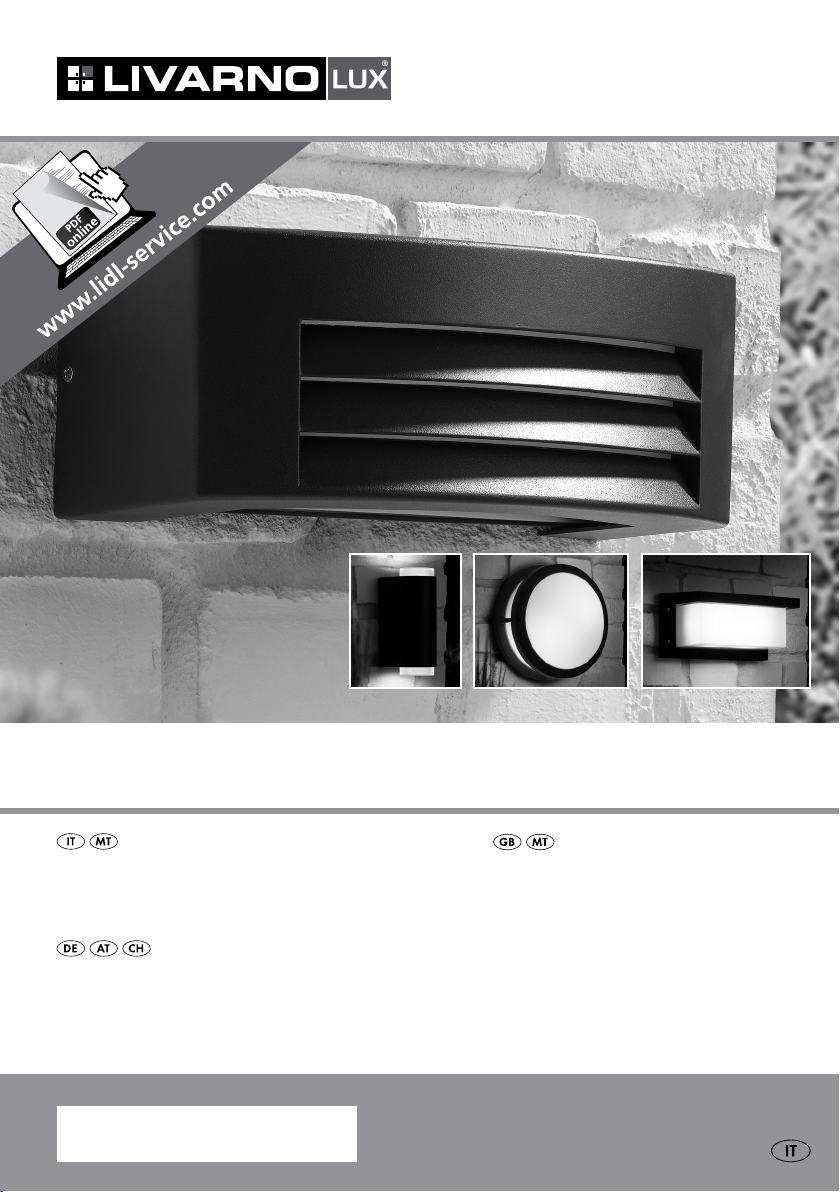
LAMPADA A LED PER ESTERNI
LAMPADA A LED PER ESTERNI
Istruzioni di montaggio, d’uso e di sicurezza
LED-AuSSENLEuchTE
Montage-, Bedienungs- und Sicherheitshinweise
IAN 106745
LED OuTDOOR LIGhT
Assembly, operating and safety instructions
Prima di leggere aprire la pagina con le immagini e prendere confidenza con le diverse funzioni
dell’apparecchio.
Before reading, unfold the page containing the illustrations and familiarise yourself with all functions of the
device.
Klappen Sie vor dem Lesen die Seite mit den Abbildungen aus und machen Sie sich anschließend
mit allen Funktionen des Gerätes vertraut.
IT / MT Istruzioni di montaggio, d’uso e di sicurezza Pagina 5
GB / MT Assembly, operating and safety instructions Page 11
DE / AT / CH Montage-, Bedienungs- und Sicherheitshinweise Seite 17
3433-025L 3434-024L
A
1
9
2
10
4 x
A
9
1 10 11
3
B
4 5
4 x
c
6 767
D D
1 2
8 8
9 9
B
c
4 x 2 x
6 767
1213
4 5
2 x
1 10 11
4 x
3
e e
13
4 x 2 x
12
A
3435-024L
9
1 2 3
10
3436-025L
A
1 2
4 x
3
2 x
10
10
B
2 x
4 5
1 14
c
6 767 8
D
9
1
2 x
2 3
B
c
D
1
4 x
86 7
14 54
3
7
15
2 x
2 x
2 x
2
e e
Indice
Introduzione
Utilizzo secondo la destinazione d’uso ......................................................................................... Pagina 6
Descrizione dei componenti ........................................................................................................... Pagina 6
Contenuto della confezione ........................................................................................................... Pagina 6
Dati tecnici ....................................................................................................................................... Pagina 6
Indicazioni per la sicurezza ......................................................................................... Pagina 7
Preparazione
Attrezzi e materiali necessari ......................................................................................................... Pagina 7
Prima dell‘installazione ................................................................................................................... Pagina 8
Montaggio .................................................................................................................................. Pagina 8
Sostituzione della lampadina ......................................................................................................... Pagina 9
Pulizia e cura ............................................................................................................................ Pagina 9
Smaltimento .............................................................................................................................. Pagina 10
Garanzia e assistenza
Garanzia ......................................................................................................................................... Pagina 10
Indirizzo servizio clienti .................................................................................................................. Pagina 10
Dichiarazione di conformità ........................................................................................................... Pagina 10
Produttore ........................................................................................................................................ Pagina 10
5 IT/MT
Lampada a LED per esterni
Introduzione
Ci congratuliamo con voi per l‘acquisto
del vostro nuovo prodotto. Acquistando
questo articolo avete scelto un prodotto
di alta qualità. Questo manuale appartiene a questo prodotto e contiene importanti indicazioni per
la sua messa in funzione e il modo in cui esso deve
essere utilizzato. Prestare sempre attenzione a tutte
le avvertenze di sicurezza. Controllare, prima della
messa in funzione, se la tensione di rete è corretta e
se tutti i componenti sono stati montati corretta
mente.
In caso di domande oppure dubbi riguardo l‘utilizzo
dell’apparecchio, contattare il proprio rivenditore
oppure il centro di assistenza. Conservare con cura
questo manuale e consegnarlo eventualmente a terzi.
Utilizzo secondo la
destinazione d’uso
Questa lampada è adatta sia per gli ambienti interni sia per quelli esterni. La lampada può essere
fissata su tutte le superfici caratterizzate da un
grado
normale di infiammabilità.
Descrizione dei componenti
1
Alloggiamento di raccordo
2
Corpo della lampada
3
Vite
4
Tasselli
5
Viti (fissaggio su parete)
6
Cavo di alimentazione
7
Morsetto
8
Guaina di protezione
9
G
uarnizione in gomma (3434-024L, 3433-025
e 3435-024L)
10
Paralume (3434-024L)
11
Copertura (3434-024L)
12
Vite (3434-024L)
13
Vite (3434-024L)
14
Lampadina (3435-024L e 3436-025L)
15
Vano di connessione (3436-025L)
6 IT/MT
Contenuto della confezione
1
Lampada a LED per esterni, modello 3433-02
3434-024L, 3435-024L o 3436-025L
4 Viti di fissaggio (3433-025L)
4 Tasselli (3433-025L)
2 Viti di fissaggio (3434-024L)
2 Tasselli (3434-024L)
2 Viti di fissaggio (3435-024L)
2 Tasselli (3435-024L)
2 Viti di fissaggio (3436-025L)
2 Tasselli (3436-025L)
2 Lampadine a LED, E14, 5,5 W (3435-024L)
2 Lampadine a LED, GU10, 5 W (3436-025L)
2 Guaine di protezione
1 Manuale di istruzioni d‘uso e di montaggio
Dati tecnici
Modello nr.: 3433-025L, 3434-024L,
3435-024L o 3436-025L
Tensione di esercizio: 230 V∼ 50 Hz
Lampadina: 2 moduli LED, ciascuno
da 5 W, non sostituibili
(modello 3433-025L e
3434-024L)
220–240 V∼ 50 Hz,
2 lampadine a LED, E14,
max. 5,5 W (3435-024L)
220–240 V∼ 50 Hz, 2
lampadine a LED, GU10,
max. 5 W (3436-025L)
Potenza nominale max: max. 10 W (3433-025L,
3434-024L)
2 x max. 5,5 W (3435-024L)
2 x max. 5 W (3436-025L)
Classe di protezione: I /
Tipo di protezione: IP44
Dimensioni: 3433-025L:
L
3434-024L:
3435-024L:
3436-025L:
250 x 125 x 125 mm
110 x 130 x 290 mm
260 x 260 x 110 mm
90 x 65 x 175 mm
5L,
Indicazioni per la sicurezza / PreparazioneIntroduzione
Indicazioni per la sicurezza
PERICOLO DI MORTE E DI IN-
CIDENTE PER INFANTI E BAMBINI! Non lasciare mai i bambini
incustoditi con il materiale d‘imballaggio. Sussis
il rischio di soffocamento a causa di tale materiale. Spesso i bambini sottovalutano i pericoli.
Tenere i bambini sempre a dovuta distanza dal
prodotto.
Pericolo di morte per
scossa elettrica!
Far eseguire l‘installazione elettrica soltanto da
un elettricista esperto o da una persona competente in materia.
Nel caso di danni a cose e persone causati dal
scorretta manipolazione o dall‘inosservanza
delle avvertenze di sicurezza, non ci assumiamo
alcuna responsabilità!
Non utilizzate mai la lampada se danneggiata.
Prima di eseguire il montaggio, rimuovere il fusibile oppure disattivare l’interruttore di sicurezza
nella scatola dei fusibili (posizione 0).
Prima del montaggio, assicurarsi che la tensione
di rete disponibile coincida con la tensione di
funzionamento necessaria della lampada
(230 V∼).
Si assicuri che durante il montaggio non ven-
gano danneggiati i tubi.
la
Fare raffreddare completamente la lampada
prima di sostituire la lampadina.
Non fissare la lampada su superficie umida o
conduttrice di elettricità.
Sostituire immediatamente le lampadine difett
con lampadine nuove. Utilizzare solamente le
te
lampadine riportate nella sezione „Dati Tec
Prima di sostituire la lampadina, rimuovere il fusibile o disattivare l‘interruttore di sicurezza della
lampada.
La lampadina integrata non è adatta per reostati
o interruttori elettronici.
Utilizzate esclusivamente i componenti forniti,
pena il decadimento di tutti i diritti di garanzia.
Come comportarsi correttamente
Utilizzare solamente lampadine da 220–240 V∼
con uno zoccolo GU10 e una potenza massima
di 5 Watt (3436-025L) o una lampadina da
220–240 V∼ con uno zoccolo E14 e con una
potenza massima si 5,5 Watt (3435-024L).
La lampada da esterno è resistente agli spruzzi
d‘acqua.
Lavorare sempre con la massima attenzione!
Prestare sempre attenzione a ciò che si fa ed
essere prudenti. Non montare la lampada, nel
caso in cui non si sia concentrati oppure non ci
si senta bene.
Preparazione
ose
nici“.
Pericolo di incendio e di lesione!
Non montare la lampada se il paralume è
danneggiato. In tal caso mettersi in contatto
con un centro di assistenza per la sostituzione.
Montare la lampada solamente su superfici
normalmente infiammabili o non infiammabili.
Un eccessivo riscaldamento della lampada può
provocare un incendio.
Per evitare ustioni, assicurarsi prima di toccare
la lampada che questa sia spenta e si sia raffreddata. Le lampadine si surriscaldano.
Attrezzi e materiali necessari
Gli attrezzi e materiali indicati non sono inclusi nella
confezione. Si tratta in questo caso di dati e valori
non vincolanti, forniti a titolo orientativo. Le caratteristiche dei materiali dipendono dalle condizioni
individuali in loco.
- Matita / strumento di marcatura
- Indicatore di tensione
- Cacciavite
- Trapano
- Punta per trapano
7 IT/MT

- Tronchese laterale
- Conduttore
Prima dell‘installazione
Importante: far eseguire l‘installazione elettrica
da un elettricista esperto o da una persona competente in materia.
Leggere le istruzioni e osservare le illustrazioni
attentamente, nonché familiarizzare con la lampada, prima di installarla.
Prima dell‘installazione, assicurarsi che non ci
sia tensione nel cavo di alimentazione di rete al
quale deve essere collegata la lampada. A tal
fine, rimuovere il fusibile oppure disattivare l‘interruttore di sicurezza nella scatola dei fusibili
(posizione 0).
Verificare l‘assenza di tensione con un rileva-
tore di tensione.
Infilare il cavo di collegamento 6 attraverso
la membrana.
Fissare l‘alloggiamento di raccordo 1 con le
5
viti
in dotazione.
Inserire la guaina di protezione 8 sul cavo di
6
rete
.
Collegare il cavo di collegamento della lam
mediante il morsetto isolante
alimentazione
6
(fig. C).
7
con il cavo di
pada
Fare attenzione anche alla connessione dei cavi
collegati in base ai colori (L o 2 = nero o marrone, N o 1 = blu).
Collegare il conduttore di protezione (3 = verde-
giallo) con il morsetto di terra contrassegnato
(fig. C).
3435-024L:
Per inserire la lampadina utilizzare un panno
pulito e privo di peli.
Inserire con attenzione la lampadina 14 E14,
5,5 W, nello zoccolo avvitarla girando in senso
orario (fig. B).
Montaggio
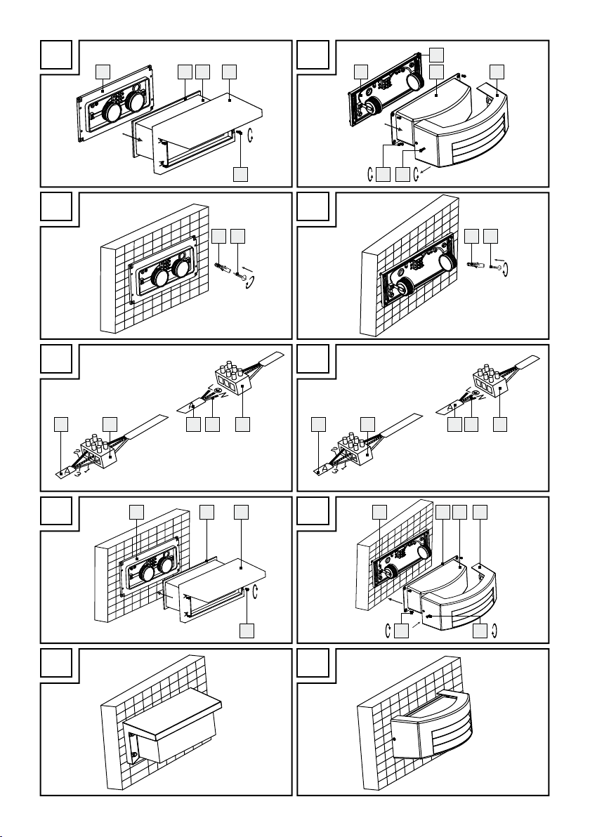
3433-025 e 3435-024L:
Svitare il corpo della lampada 2 dall‘allog-
giamento di raccordo
senso antiorario (fig. A).
3434-024L:
Svitare la copertura 11 dall‘alloggiamento di
raccordo
1
girando le viti 12 in senso antiorario (fig. A).
Svitare il
paralume
cordo 1 girando le voto 13 in senso antiorario.
3433-025L, 3434-024L e 3435-024L:
Contrassegnare i fori da eseguire con l‘aiuto dei
fori presenti sull‘alloggiamento di raccordo
e destinati alle viti.
Eseguire ora i fori di fissaggio (ø ca. 6 mm, pro-
fondità ca. 40 mm). Assicurarsi di non danneggiare il cavo di alimentazione di rete.
Inserire ora i tasselli 4 nei fori.
Aprire la membrana per il cavo di collegamento
6
con una spina o con la punta di un coltello.
8 IT/MT
1
girando le viti 3 in
10 dall‘alloggiamento di rac-
3433-025 e 3435-024L:
Riavvitare il corpo della lampada 2 sull‘allog-
giamento di raccordo
1
girando le viti 3 in
senso orario (fig. D). Assicurarsi che le guarnizioni in gomma
9
siano nella giusta posizione.
3434-024L:
Avvitare il paralume 10 sull‘alloggiamento di
raccordo
1
girando le viti 13 in senso orario.
Assicurarsi che le guarnizioni in gomma 9
siano nella giusta posizione.
Avvitare la copertura 11
girando le viti
12
sul
paralume 10
in senso orario (fig. D).
3433-025L, 3434-024L e 3435-024L:
Controllare che siano correttamente in sede.
1
La lampada è ora pronta per essere utilizzata
(fig. E).
Reinserire il fusibile oppure attivare nuovamente
l‘interruttore di sicurezza nella scatola dei fusibili.
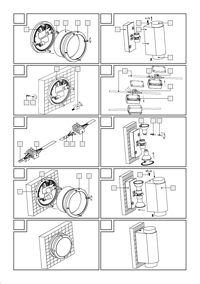
3436-025L:
Svitare il corpo della lampada 2 dall‘alloggia-
mento di raccordo 1 girando le viti 3 in
antiorario (fig. A).
senso

Montaggio / Pulizia e curaPreparazione / Montaggio
Contrassegnare i fori da eseguire con l‘aiuto dei
fori presenti sull‘alloggiamento di raccordo
1
e destinati alle viti. Assicurarsi di fissare l‘alloggiamento di raccordo
1
con la freccia rivolta
verso l‘alto (sul retro dell‘alloggiamento di raccordo).
Eseguire ora i fori di fissaggio (ø ca. 6 mm, pro-
fondità ca. 40 mm). Assicurarsi di non danneggiare il cavo di alimentazione di rete.
Inserire ora i tasselli 4 nei fori.
Aprire il vano di connessione 15 sul lato poste-
riore dell‘alloggiamento di raccordo
1
.
Inserire la guaina di protezione 8 sul cavo di
6
rete
.
Collegare il cavo di collegamento della lam
mediante il morsetto isolante
alimentazione
6
(fig. B).
7
con il cavo di
pada
Fare attenzione anche alla connessione dei cavi
collegati in base ai colori (L o 2 = nero o marrone, N o 1 = blu).
Collegare il conduttore di protezione (3 = verde-
giallo) con il morsetto di terra contrassegnato
(fig. B).
Chiudere il vano di connessione 15 sul lato po-
steriore dell‘alloggiamento di raccordo
1
.
Fissare l‘alloggiamento di raccordo 1 con le
5
viti
in dotazione (fig. C).
Per inserire la lampadina utilizzare un panno
pulito e privo di peli.
Inserire con attenzione la lampadina 14 GU
10, 5 W nel portalampada e avvitarla girandola
di ¼ in senso orario.
Riavvitare il corpo della lampada 2 sull‘allog-
giamento di raccordo
1
girando le viti 3 in
senso orario (fig. D).
Controllare che siano correttamente in sede.
La lampada è ora pronta per essere utilizzata
(fig. E).
Reinserire il fusibile oppure attivare nuovamente
l‘interruttore di sicurezza nella scatola dei fusibili.
ATTENZIONE! PERICOLO DI SCOSSA
ELETTRICA!
Prima di sostituire la lampadina staccare la lam-
pada dall’alimentazione di rete. Rimuovere perciò il fusibile oppure disattivare l‘interruttore di
sicurezza nella scatola dei fusibili (posizione 0).
Lasciare raffreddare completamente la lampada.
Per la sostituzione utilizzare un panno asciutto
e privo di peli.
3435-024L:
Svitare il corpo della lampada 2 dall‘allog-
giamento di raccordo
1
girando le viti 3 in
senso antiorario (fig. A).
Girare la lampadina difettosa 14 in senso an-
tiorario fuori dalla montatura.
Inserire con attenzione una nuova lampadina
nel portalampada e avvitarla in senso orario.
Controllare che siano correttamente in sede.
Riavvitare il corpo della lampada 2 sull‘allog-
giamento di raccordo
senso orario (fig. D).
1
girando le viti 3 in
3436-025L:
Svitare il corpo della lampada 2 dall‘allog-
giamento di raccordo
1
girando le viti 3 in
senso antiorario (fig. A).
Svitare la lampadina difettosa 14 girandola di
¼ in senso antiorario.
Inserire una nuova lampadina nel portalampada
e fissarla girandola di ¼ in senso orario.
Controllare che siano correttamente in sede.
Riavvitare il corpo della lampada 2 sull‘allog-
giamento di raccordo
1
girando le viti 3 in
senso orario (fig. D).
Reinserire il fusibile oppure attivare nuovamente
l‘interruttore di sicurezza nella scatola dei fusibili.
Pulizia e cura
Sostituzione della lampadina
(3435-024L / 3436-025L)
Nota: per il modello 3433-025L e 3434-024L la
lampadina / il modulo LED non è sostituibile.
ATTENZIONE! PERICOLO DI SCOSSA
ELETTRICA! Prima di ogni intervento di pulizia,
staccare la lampada dall’alimentazione elett
Rimuovere perciò il fusibile oppure disattivare
l‘interruttore di sicurezza nella scatola dei fusi-
bili (posizione 0).
rica.
9 IT/MT

Pulizia e cura / Smaltimento / Garanzia e assistenza
Non usare solventi, benzina o simili. La lampada
verrebbe danneggiata.
Lasciare raffreddare completamente la lampada
Per la pulizia utilizzare solamente un panno
asciutto e privo di peli.
Reinserire il fusibile oppure attivare nuovamente
l‘interruttore di sicurezza nella scatola dei fusibili.
Smaltimento
La confezione e il materiale da imballaggio sono composti esclusivamente da materiale ecologico. Essi possono essere
smaltiti nei contenitori di riciclaggio locali.
Il simbolo del bidone della spazzatura
su ruote barrato indica che nell’Unione
Europea il prodotto deve essere smaltito
attraverso una raccolta differenziata di rifiuti. Ciò
vale per il prodotto, nonché per tutti i componenti
contrassegnati con questo simbolo. I prodotti contrassegnati in questo modo non devono essere smaltiti
attraverso la normale raccolta di rifiuti domestici,
ma consegnati in un punto di raccolta speciale per
il riciclaggio di apparecchi elettrici ed elettronici. Il
riciclaggio aiuta a ridurre il consumo di materie p
e a non contaminare l’ambiente naturale.
rime
Garanzia e assistenza
Garanzia
L’acquirente acquisisce il diritto alla garanzia per
36 mesi a partire dalla data di acquisto dell’apparecchio. L‘apparecchio è stato prodotto con cura ed
è stato sottoposto ad un preciso controllo di qualità.
All’interno del periodo di garanzia tutti i difetti di
materiale e di produzione vengono eliminati gratuitamente. Qualora tuttavia, nel corso del periodo di
garanzia dovessero manifestarsi eventuali vizi, si
prega di inviare l’apparecchio all’indirizzo del Centro di Assistenza indicato, specificando il seguente
numero di articolo: 3433-025L, 3434-024L,
3435-024L o 3436-025L.
Sono esclusi dalla garanzia danni per uso non appropriato, mancata osservanza delle istruzioni d‘uso
.
o intervento da parte di persone non autorizzate come
lo sono anche le parti di consumo (come p.e. le lampadine). Un eventuale intervento in base al diritto
di garanzia non prolunga né fa riavviare il tempo
di garanzia.
Indirizzo servizio clienti
Briloner Leuchten GmbH
Im Kissen 2, 59929 Brilon, Germania
Tel.: +49 2961 / 9712-800
Fax: +49 2961 / 9712-199
E-Mail: kundenservice@briloner.com
www.briloner.de
IAN 106745
Per tutte le richieste si prega di conservare lo scontrino ed il codice dell‘ articolo (p.e. IAN 12345) a
prova dell‘avvenuto acquisto.
Dichiarazione di conformità
Questo prodotto è conforme ai requisiti di cui alle
direttive europee e nazionali (compatibilità elettromagnetica CE 2004 / 108 , direttiva sulla bassa
tensione CE 2006 / 95/EG , Direttiva Eco-design
2009 / 125 / EG, Direttiva RoHS 2011 / 65 / EU).
La conformità è stata comprovata. Le relative dichiarazioni e la documentazione in merito sono depositate presso il produttore.
Produttore
Briloner Leuchten GmbH
Im Kissen 2
59929 Brilon
Germania
10 IT/MT

Introduction
Intended use ........................................................................................................................................ Page 12
Parts description .................................................................................................................................. Page 12
Scope of delivery ................................................................................................................................ Page 12
Technical Data ....................................................................................................................................Page 12
Safety notices ..............................................................................................................................Page 13
Preparation
Required tools and material ............................................................................................................... Page 13
Prior to installation ............................................................................................................................... Page 14
Installation ..................................................................................................................................... Page 14
Replacing lamps .................................................................................................................................. Page 15
Cleaning and Care ................................................................................................................... Page 15
Disposal ............................................................................................................................................ Page 15
Warranty and Service
Warranty .............................................................................................................................................Page 16
Service address ................................................................................................................................... Page 16
Declaration of conformity ................................................................................................................... Page 16
Manufacturer ....................................................................................................................................... Page 16
11 GB/MT

LED Outdoor Light
Introduction
Congratulations on the purchase of your
new product. You have selected a high
quality product. These instructions are pa
of the product and contain important information on
setup and handling. Always follow all safety instructions. Before using this product for the first time verify
the correct voltage and that all parts are properly
installed. Should you have any questions or you are
unsure about operating the product, please contact
the dealer or service centre. Please keep these instructions in a safe place and pass them on to third
parties as applicable.
Intended use
This light is suitable for indoor and outdoor use.
The light can be fastened to any normally inflammable surface.
Parts description
1
Connection housing
2
Light body
3
Screw
4
Rawlplug
5
Screw (for wall fastening)
6
Mains connection lead
7
Terminal block
8
Protective tube
9
Rubber seal (3434-024L, 3433-025L and
3435-024L)
10
Lamp shade (3434-024L)
11
Cover (3434-024L)
12
Screw (3434-024L)
13
Screw (3434-024L)
14
LED Lamp (3435-024L and 3436-025L)
15
Connection socket (3436-025L)
Scope of delivery
1
LED outdoor light, model 3433-025L, 3434-024L,
3435-024L or 3436-025L
4 Fixing screws (3433-025L)
4 Rawlplugs (3433-025L)
2 Fixing screws (3434-024L)
2 Rawlplugs (3434-024L)
rt
2 Fixing screws (3435-024L)
2 Rawlplugs (3435-024L)
2 Fixing screws (3436-025L)
2 Rawlplugs (3436-025L)
2 LED lamps, E14, 5.5 W (3435-024L)
2 LED lamps, GU10, 5 W (3436-025L)
2 Protective tubes
1 Instructions for assembly and use
Technical Data
Model No.: 3433-025L, 3434-024L,
3435-024L or 3436-025L
Operating voltage: 230 V∼ 50 Hz
Illuminant: 2 LED modules, each 5 W, not
replaceable (model 3433-025
and 3434-024L)
220–240 V∼ 50 Hz, 2 LED
lamps, E14, max. 5.5 W
(3435-024L) 220–240 V∼
50 Hz, 2 LED lamps, GU10,
max. 5 W (3436-025L)
Rated power max.: max. 10 W (3433-025L,
3434-024L)
2 x max. 5.5 W (3435-024L)
2 x max. 5 W (3436-025L)
Protection class: I /
Protection type: IP44
Dimensions: 3433-025L:
250 x 125 x 125 mm
3434-024L:
110 x 130 x 290 mm
3435-024L:
260 x 260 x 110 mm
3436-025L:
90 x 65 x 175 mm
L
12 GB/MT

Safety notices
DANGER TO LIFE AND ACCI-
DENT HAZARD FOR TODDLERS
AND SMALL CHILDREN! Never
leave children unattended with the packaging
material. The packaging material represents a
danger of suffocation. Children frequently underestimate the dangers. Please keep children
away from the product at all times.
Danger to life from
electric shock!
Ensure that a qualified electrician, or a person
trained to carry out electrical installations, performs the electrical installation.
We assume no liability for material damage or
personal injury due to improper handling or
failure to comply with the safety instructions!
Never use the light if any defects have been
identified. Prior to installation, remove the fuse
or switch off the circuit breaker 0 position in the
fuse box.
Prior to installation, verify that the mains voltage
to be used corresponds with the operating voltage required for the light (230 V∼).
Be careful not to damage lines during installatio
Risk of burns and injury!
Do not install the light if the lamp shade is
defective. Should this be the case, contact the
service centre for a replacement.
Only install the light on normally inflammable or
non-inflammable surfaces. Excessive heat can
result in a fire.
To prevent burns, ensure that the light is switched
off and has cooled down before touching it.
Lamps become very hot.
Allow the light to cool down completely before
replacing a defective bulb.
Do not attach the light to a damp or conductive
substrate.
n.
Safety notices / PreparationIntroduction
Replace defective lamps with new ones imme-
diately. Use only lamps as stated in the chapter
“Technical Data”. Before changing lamps, alwa
first remove the fuse or switch off the circuit
breaker.
The type of lamp included is not suitable for
dimmer or electronic switches.
Only use the individual parts supplied, other-
wise all warranty claims will become invalid.
Safe working
Only use 220–240 V∼ LED lamps with an
GU10 socket and a maximum power of 5 Watts
(3436-025) or 220–240 V∼ LED lamps with an
E14 socket and a maximum power of 5.5 Watts
(3435-024L).
The outdoor light is splash-proof.
Always be attentive! Always pay attention to
what you are doing and use common sense.
Never install the light if you are having difficulty
concentrating or do not feel well.
Preparation
Required tools and material
The tools and materials specified are not included.
This information and these values are non-binding
and are only provided as a reference. The nature
of the material is determined by the individual local
conditions.
- Pencil / marking tool
- Voltage tester
- Screwdriver
- Electric drill
- Drill bit
- Side cutting pliers
- Ladder
ys
13 GB/MT

Prior to installation
Important: Ensure that a qualified electrician, or
a person trained to carry out electrical installations,
performs the electrical installation.
Familiarise yourself with all the instructions and
diagrams in this manual, as well as with the light
itself, before you install it.
Before installation ensure that the circuit, to which
the light will be connected, is not energised. To
do this, remove the fuse or switch off the circuit
breaker in the fuse box 0 position.
Use the voltage tester to verify the de-energised
status.
Installation
3433-025L and 3435-024L:
Unscrew the light body 2 from the connection
housing
ter-clockwise (Fig. A).
3434-024L:
Unscrew the cover 11 from the connection
housing
ter-clockwise (Fig A).
Unscrew the lamp shade 10 from the connec-
tion housing
counter-clockwise.
3433-025L, 3434-024L and 3435-024L:
Use the holes in the connection housing 1,
which are intended for the screws, to mark the
drill holes.
Now drill the fixing holes (ø approx. 6 mm, depth
approx. 40 mm). Be careful not to damage the
supply line.
Now insert the rawlplugs 4 into the drill holes.
Open the membrane for the mains connection
lead
Insert the mains connection lead 6 through the
membrane.
Fasten the connection housing 1 with the screws
included in delivery
Pull the protective tube 8 over the mains con-
nection lead
14 GB/MT
1
by loosening the screws 3 coun-
1
by loosening the screws 12 coun-
1
by loosening the screws 13
6
with a thorn or a sharp knife.
5
.
6
.
Connect the connection cable of the light to
the power cord
6
using the terminal block 7
(Fig. C).
Also ensure that the colour connection of the
wires is correct when connecting (L or 2 = black
or brown, N or 1 = blue).
Now connect the earth wire (3 = green-yellow)
to the marked earth terminal
(see Fig. C).
3435-024L:
Use a clean, lint-free cloth to insert the lamp.
Carefully insert the lamp 14 E14, 5.5 W, into
the socket and tighten clockwise (Fig. B).
3433-025L and 3435-024L:
Screw the light body 2 to the connection
housing
1
again by tightening the screws 3
clockwise (Fig. D). Ensure the rubber seals
are positioned correctly.
3434-024L:
Screw the lamp shade 10 to the connection
housing
1
by tightening the screws 13 clockwise.
Ensure the rubber seals 9 are positioned
correctly.
Screw the cover 11 to the lamp shade 10 by
tightening the screws
12
clockwise (Fig. D).
3433-025L, 3434-024L and 3435-024L:
Check for correct fitting.
Your light is now ready for use (Fig. E).
Reinsert the fuse or switch the circuit breaker
back on.
3436-025L:
Unscrew the light body 2 from the connection
housing
1
by loosening the screws 3 counter-clockwise (Fig. A).
Use the holes in the connection housing 1, wh
are intended for the screws, to mark the drill hole
Ensure that that you fasten the connection hous-
1
ing
with the arrow facing upwards (on the
rear of the connection housing).
Now drill the fixing holes (ø approx. 6 mm,
depth approx. 40 mm). Be careful not to damage the supply line.
Now insert the rawlplugs 4 into the drill holes.
9
ich
s.

Installation / Cleaning and Care / DisposalPreparation / Installation
Open the connection socket 15 on the rear of
the connection housing
1
.
Pull the protective tube 8 over the mains con-
nection lead
6
.
Connect the connection cable of the light to
the power cord
6
using the terminal block 7
(Fig. B).
Also ensure that the colour connection of the
wires is correct when connecting (L or 2 = black
or brown, N or 1 = blue).
Connect the earth wire (3 = green-yellow) to the
marked earth terminal
(Fig. B).
Close the connection socket 15 on the rear of
the connection housing
1
.
Fasten the connection housing 1 with the screws
which are included
5
(Fig. C).
Use a clean, lint-free cloth to insert the lamp.
Insert the bulb 14 GU10, 5 W, into the socket
carefully and tighten it with a ¼ turn in a clockwise direction.
Screw the light body 2 to the connection hous-
1
ing
again by tightening the screws 3 clock-
wise (Fig. D).
Check for correct fitting.
Your light is now ready for use (Fig. E).
Reinsert the fuse or switch the circuit breaker
back on.
Twist the defective lamp 14 anti-clockwise out
of the bulb socket.
Carefully insert a new lamp into the socket and
tighten clockwise.
Check for correct fitting.
Screw the light body 2 to the connection
housing
1
again by tightening the screws 3
clockwise (Fig. D).
3436-025L:
Unscrew the light body 2 from the connection
housing
1
by loosening the screws 3 coun-
ter-clockwise (Fig. A).
Twist the defective lamp 14 with a ¼-turn anti-
clockwise out of the bulb socket.
Insert a new lamp into the socket and tighten it
with a ¼-turn clockwise.
Check for correct fitting.
Screw the light body 2 to the connection
housing
1
again by tightening the screws 3
clockwise (Fig. D).
Reinsert the fuse or switch the circuit breaker
back on.
Cleaning and Care
Replacing lamps (3435-024L /
3436-025L)
Note: The light / LED module is not replaceable in
models 3433-025L and 3434-024L.
CAUTION! RISK OF ELECTRIC SHOCK!
To replace the lamp, first disconnect the light
from the mains circuit. To do so, remove the fuse
or switch off the circuit breaker in the fuse box
0 position.
Allow the light to cool down completely.
Use a dry, lint-free cloth when replacing a lamp.
3435-024L:
Unscrew the light body 2 from the connection
housing
ter-clockwise (Fig. A).
1
by loosening the screws 3 coun-
CAUTION! RISK OF ELECTRIC SHOCK!
Disconnect the light from the mains circuit before
cleaning. To do so, remove the fuse or switch off
the circuit breaker in the fuse box 0 position.
Do not use solvents, petrol, etc. Otherwise the
light will be damaged.
Allow the light to cool down completely.
Only use a dry, lint-free cloth for cleaning.
Reinsert the fuse or switch the circuit breaker
back on.
Disposal
The package and packaging materials
consist entirely of environmentally friendly
materials. They can be disposed of at
your local recycling facility.
15 GB/MT

The symbol of the wheelie bin with the
line through it means that, in the European
Union, the product has to be disposed
of in a separate refuse collection. This applies to the
product and to all components bearing this symbol.
Do not dispose of products bearing this symbol in
your normal household waste, but instead they must
be taken for recycling to a collection site for electrical and electronic appliances. Recycling helps to
reduce the consumption of raw materials and protects the environment.
Warranty and Service
Warranty
You receive a 36 month warranty on this product,
valid from the date of purchase. The appliance has
been carefully produced under strict quality control.
Within the warranty period we shall rectify without
charge all material and manufacturing defects. In
event of a defect arising during the warranty period,
please send the appliance to the listed Service Centre
address, making reference to the following article
number: 3433-025L, 3434-024L, 3435-024L or
3436-025L.
Damage caused by improper handling, non-observance of the operating instructions or unauthorised
interference are excluded from the warranty. The
performance of services under the warranty does
not extend or renew the warranty period.
the
Declaration of conformity
This product fulfils the requirements of the applicable
European and national directives (Electromagnetic
Compatibility 2004 / 108 / EC, Low Voltage
Directive 2006 / 95 / EC, Ecodesign Directive
2009 / 125 / EC, RoHS Directive 2011 / 65 / EU).
Conformity has been demonstrated.
The relevant declarations and documents are held
by the manufacturer.
Manufacturer
Briloner Leuchten GmbH
Im Kissen 2
59929 Brilon
Germany
Service address
Briloner Leuchten GmbH
Im Kissen 2, 59929 Brilon, Germany
Tel.: +49 2961 / 9712-800
Fax: +49 2961 / 9712–199
E-Mail: kundenservice@briloner.com
www.briloner.de
IAN 106745
Please have your receipt and the article number
(e.g. IAN 12345) ready as your proof of purchase
when enquiring about your product.
16 GB/MT

Inhaltsverzeichnis
Einleitung
Bestimmungsgemäße Verwendung .................................................................................................... Seite 18
Teilebeschreibung ............................................................................................................................... Seite 18
Lieferumfang ........................................................................................................................................ Seite 18
Technische Daten ................................................................................................................................ Seite 18
Sicherheitshinweise ................................................................................................................ Seite 19
Vorbereitung
Benötigtes Werkzeug und Material ................................................................................................... Seite 19
Vor der Installation .............................................................................................................................. Seite 20
Montage ........................................................................................................................................... Seite 20
Leuchtmittel auswechseln .................................................................................................................... Seite 21
Reinigung und Pflege ............................................................................................................ Seite 22
Entsorgung ..................................................................................................................................... Seite 22
Garantie und Service
Garantie ..............................................................................................................................................Seite 22
Serviceadresse ....................................................................................................................................Seite 22
Konformitätserklärung ......................................................................................................................... Seite 22
Hersteller .............................................................................................................................................. Seite 22
17 DE/AT/CH

LED-Außenleuchte
Einleitung
Wir beglückwünschen Sie zum Kauf Ihres
neuen Produkts. Sie haben sich damit für
ein hochwertiges Produkt entschieden.
Diese Anleitung gehört zu diesem Produkt und enthält
wichtige Hinweise zur Inbetriebnahme und Handhabung. Beachten Sie immer alle Sicherheitshinweise.
Prüfen Sie vor der Inbetriebnahme, ob die korrekte
Spannung vorhanden ist und ob alle Teile richtig montiert sind. Sollten Sie Fragen haben oder unsicher in
Bezug auf die Handhabung des Gerätes sein, setzen
Sie sich bitte mit Ihrem Händler oder der Servicestelle
in Verbindung. Bewahren Sie diese Anleitung bitte
sorgfältig auf und geben Sie sie ggf. an Dritte weiter.
Lieferumfang
1 LED-Außenleuchte, Modell 3433-025L,
3434-024L, 3435-024L oder 3436-025L
4 Befestigungsschrauben (3433-025L)
4 Dübel (3433-025L)
2 Befestigungsschrauben (3434-024L)
2 Dübel (3434-024L)
2 Befestigungsschrauben (3435-024L)
2 Dübel (3435-024L)
2 Befestigungsschrauben (3436-025L)
2 Dübel (3436-025L)
2 LED-Leuchtmittel, E14, 5,5 W (3435-024L)
2 LED-Leuchtmittel, GU10, 5 W (3436-025L)
2 Schutzschläuche
1 Montage- und Bedienungsanleitung
Technische Daten
Bestimmungsgemäße
Verwendung
Diese Leuchte ist für den Betrieb im Innen- und Außenbereich geeignet. Die Leuchte kann auf allen normal
entflammbaren Oberflächen befestigt werden.
Teilebeschreibung
1
Anschlussgehäuse
2
Leuchtenkörper
3
Schraube
4
Dübel
5
Schraube (Wandbefestigung)
6
Netzanschlusskabel
7
Lüsterklemme
8
Schutzschlauch
9
Gummi-Dichtung (3434-024L, 3433-025L
und 3435-024L)
10
Lampenschirm (3434-024L)
11
Abdeckung (3434-024L)
12
Schraube (3434-024L)
13
Schraube (3434-024L)
14
Leuchtmittel (3435-024L und 3436-025L)
15
Anschlussdose (3436-025L)
Modellnr.: 3433-025L, 3434-024L,
3435-024L oder 3436-025L
Betriebsspannung: 230 V∼ 50 Hz
Leuchtmittel: 2 LED-Module, je 5 W, nicht
austauschbar (Modell 3433-
025L und 3434-024L)
220–240 V∼ 50 Hz, 2 LED-
Leuchtmittel, E14, max. 5,5 W
(3435-024L)
220–240 V∼ 50 Hz, 2 LED-
Leuchtmittel, GU10, max. 5 W
(3436-025L)
Nennleistung max.: max. 10 W (3433-025L,
3434-024L)
2 x max. 5,5 W (3435-024L)
2 x max. 5 W (3436-025L)
Schutzklasse: I /
Schutzart: IP44
Abmessungen: 3433-025L:
250 x 125 x 125 mm
3434-024L:
110 x 130 x 290 mm
3435-024L:
260 x 260 x 110 mm
3436-025L:
90 x 65 x 175 mm
18 DE/AT/CH

Sicherheitshinweise
LEBENS- UND UNFALLGEFAHR
FÜR KLEINKINDER UND KINDER! Lassen Sie Kinder niemals un-
beaufsichtigt mit dem Verpackungsmaterial. Es
besteht Erstickungsgefahr durch Verpackungsmaterial. Kinder unterschätzen häufig die Gefahren. Halten Sie Kinder stets vom Produkt fern.
Lebensgefahr durch
elektrischen Schlag!
Lassen Sie die Elektroinstallation durch einen
ausgebildeten Elektriker oder eine für Elektroinstallationen eingewiesene Person durchführen.
Bei Sach- oder Personenschäden, die durch
unsachgemäße Handhabung oder Nichtbeachtung der Sicherheitshinweise verursacht
werden, wird keine Haftung übernommen!
Benutzen Sie Ihre Leuchte niemals, wenn Sie
irgendwelche Beschädigungen feststellen. Entfernen Sie vor der Montage die Sicherung oder
schalten Sie den Leitungsschutzschalter im Sicherungskasten aus (0-Stellung).
Vergewissern Sie sich vor der Montage, dass die
vorhandene Netzspannung mit der benötigten
Betriebsspannung der Leuchte übereinstimmt
(230 V∼).
Stellen Sie sicher, dass bei der Montage keine
Leitungen beschädigt werden.
Sicherheitshinweise / VorbereitungEinleitung
Lassen Sie die Leuchte vor dem Ersetzen eines
defekten Leuchtmittels vollständig auskühlen.
Befestigen Sie die Leuchte nicht auf feuchtem
oder leitendem Untergrund.
Ersetzen Sie defekte Leuchtmittel sofort durch neue.
Verwenden Sie nur Leuchtmittel wie im Kapitel
„Technische Daten“ angegeben. Entfernen Sie
vor dem Leuchtmittelwechsel immer zuerst die
Sicherung oder schalten Sie den Leitungsschutzschalter aus.
Das beiliegende Leuchtmittel ist nicht geeignet
für Dimmer und elektronische Schalter.
Verwenden Sie ausschließlich die mitgelieferten
Einzelteile, ansonsten erlöschen alle Gewährleistungsansprüche.
So verhalten Sie sich richtig
Verwenden Sie nur 220–240 V∼ Leuchtmittel
mit GU10-Fassung und einer Höchstleistung
von 5 Watt (3436-025L) bzw. 220–240 V∼
Leuchtmittel mit E14-Fassung und einer Höchst-
leistung von 5,5 Watt (3435-024L).
Die Außenleuchte ist spritzwassergeschützt.
Seien Sie stets aufmerksam! Achten Sie immer
darauf was Sie tun und gehen Sie stets mit Ver-
nunft vor. Montieren Sie die Leuchte in keinem
Fall, wenn Sie unkonzentriert sind oder sich un-
wohl fühlen.
Vorbereitung
Brand- und Verletzungsgefahr!
Montieren Sie die Leuchte nicht mit defektem
Lampenschirm. Setzen Sie sich in diesem Fall
für Ersatz mit der Servicestelle in Verbindung.
Montieren Sie die Leuchte nur auf normal- oder
nicht entflammbaren Flächen. Eine übermäßige
Wärmeentwicklung kann zu Brandentwicklung
führen.
Stellen Sie sicher, dass die Leuchte ausgeschal-
tet und abgekühlt ist, bevor Sie diese berühren,
um Verbrennungen zu vermeiden. Leuchtmittel
entwickeln eine starke Hitze.
Benötigtes Werkzeug
und Material
Die genannten Werkzeuge und Materialien sind nicht
im Lieferumfang enthalten. Es handelt sich hierbei
unverbindliche Angaben und Werte zur Orientierung. Die Beschaffenheit des Materials richtet sich
nach den individuellen Gegebenheiten vor Ort.
- Bleistift / Markierwerkzeug
- Spannungsprüfer
- Schraubendreher
- Bohrmaschine
um
19 DE/AT/CH

- Bohrer
- Seitenschneider
- Leiter
Vor der Installation
Wichtig: Lassen Sie die Elektroinstallation durch
einen ausgebildeten Elektriker oder eine für Elektroinstallationen eingewiesene Person durchführen.
Machen Sie sich vor der Installation mit allen
Anweisungen und Abbildungen in dieser Anleitung sowie mit der Leuchte selbst vertraut.
Stellen Sie vor der Installation sicher, dass an
der Leitung, an der die Leuchte angeschlossen
werden soll, keine Spannung vorliegt. Entfernen
Sie hierfür die Sicherung oder schalten Sie den
Leistungsschutzschalter im Sicherungskasten aus
(0-Stellung).
Überprüfen Sie die Spannungsfreiheit mittels
Spannungsprüfer.
Montage
Öffnen Sie die Membran für das Netzanschluss-
6
kabel
mit einem Dorn oder einem spitzen
Messer.
Führen Sie das Netzanschlusskabel 6 durch
die Membran.
Befestigen Sie das Anschlussgehäuse 1 mit den
beiliegenden Schrauben
5
.
Ziehen Sie die Schutzschläuche 8 über das
Netzanschlusskabel
6
.
Verbinden Sie das Anschlusskabel der Leuchte
mittels der Lüsterklemme
schlusskabel
6
(Abb. C).
7
mit dem Netzan-
Achten Sie auch auf den farblichen Zusammen-
schluss der angeschlossenen Leitungen (L bzw.
2 = schwarz oder braun, N bzw. 1 = blau).
Verbinden Sie nun den Schutzleiter (3 = grün-gelb)
mit der gekennzeichneten Erdungsklemme
(Abb. C).
3435-024L:
Benutzen Sie zum Einsetzen des Leuchtmittels
ein sauberes, fusselfreies Tuch.
Stecken Sie das Leuchtmittel 14 E14, 5,5 W,
vorsichtig in die Fassung und drehen Sie es im
Uhrzeigersinn fest (Abb. B).
3433-025L und 3435-024L:
Schrauben Sie den Leuchtenkörper 2 vom An-
schlussgehäuse
3
gegen den Uhrzeigersinn lösen (Abb. A).
1
ab, indem Sie die Schrauben
3434-024L:
Schrauben Sie die Abdeckung 11 vom An-
schlussgehäuse
12
gegen den Uhrzeigersinn lösen (Abb. A).
1
ab, indem Sie die Schrauben
Schrauben Sie den Lampenschirm 10 vom An-
schlussgehäuse
13
gegen den Uhrzeigersinn lösen.
1
ab, indem Sie die Schrauben
3433-025L, 3434-024L und 3435-024L:
Markieren Sie die Bohrlöcher mit Hilfe der im
Anschlussgehäuse
1
für die Schrauben vorge-
sehenen Löcher.
Bohren Sie nun die Befestigungslöcher (ø ca.
6 mm, Tiefe ca. 40 mm). Stellen Sie sicher, dass
Sie die Zuleitung nicht beschädigen.
F
ühren Sie nun die Dübel 4 in die Bohrlöcher ei
20 DE/AT/CH
3433-025L und 3435-024L:
Schrauben Sie den Leuchtenkörper 2 wieder
auf das Anschlussgehäuse
Schrauben
3
im Uhrzeigersinn festziehen
1
, indem Sie die
(Abb. D). Achten Sie auf den korrekten Sitz der
Gummi-Dichtungen
9
.
3434-024L:
Schrauben Sie den Lampenschirm 10 auf das
Anschlussgehäuse
13
ben
im Uhrzeigersinn festziehen.
1
, indem Sie die Schrau-
Achten Sie auf den korrekten Sitz der Gummi-
Dichtungen
9
.
Schrauben Sie die Abdeckung 11 auf den
Lampenschirm
10
, indem Sie die Schrauben 12
im Uhrzeigersinn festziehen (Abb. D).
3433-025L, 3434-024L und 3435-024L:
Überprüfen Sie den richtigen Sitz.
Ihre Leuchte ist nun betriebsbereit (Abb. E).
n.
Setzen Sie die Sicherung wieder ein oder
schalten Sie den Leitungsschutzschalter wieder a
n.

MontageVorbereitung / Montage
3436-025L:
Schrauben Sie den Leuchtenkörper 2 vom An-
schlussgehäuse
3
gegen den Uhrzeigersinn lösen (Abb. A).
1
ab, indem Sie die Schrauben
Markieren Sie die Bohrlöcher mit Hilfe der im
Anschlussgehäuse
1
für die Schrauben vorgesehenen Löcher. Achten Sie darauf, dass Sie
das Anschlussgehäuse
1
mit dem Pfeil nach
oben befestigen (auf der Rückseite des Anschlussgehäuses).
Bohren Sie nun die Befestigungslöcher (ø ca.
6 mm, Tiefe ca. 40 mm). Stellen Sie sicher, dass
Sie die Zuleitung nicht beschädigen.
Führen Sie nun die Dübel 4 in die Bohrlöcher ein.
Öffnen Sie die Anschlussdose 15 auf der Rück-
seite des Anschlussgehäuses
1
.
Ziehen Sie die Schutzschläuche 8 über das
Netzanschlusskabel
6
.
Verbinden Sie das Anschlusskabel der Leuchte
mittels der Lüsterklemme
schlusskabel
6
(Abb. B).
7
mit dem Netzan-
Achten Sie auch auf den farblichen Zusammen-
schluss der angeschlossenen Leitungen (L bzw.
2 = schwarz oder braun, N bzw. 1 = blau).
Verbinden Sie nun den Schutzleiter (3 = grün-gel
mit der gekennzeichneten Erdungsklemme
(Abb. B).
Schließen Sie die Anschlussdose 15 auf der
Rückseite des Anschlussgehäuses
1
.
Befestigen Sie das Anschlussgehäuse 1 mit
den beigelegten Schrauben
5
(Abb. C).
Benutzen Sie zum Einsetzen des Leuchtmittels
ein sauberes, fusselfreies Tuch.
Stecken Sie die Leuchtmittel 14 GU10, 5 W,
vorsichtig in die Fassung und drehen Sie sie mit
einer ¼-Umdrehung im Uhrzeigersinn fest.
Schrauben Sie den Leuchtenkörper 2 wieder
auf das Anschlussgehäuse
Schrauben
3
im Uhrzeigersinn festziehen
1
, indem Sie die
(Abb. D).
Überprüfen Sie den richtigen Sitz.
Ihre Leuchte ist nun betriebsbereit (Abb. E).
Setzen Sie die Sicherung wieder ein oder schal-
ten Sie den Leitungsschutzschalter wieder an.
Leuchtmittel auswechseln
(3435-024L / 3436-025L)
Hinweis: Bei Modell 3433-025L und 3434-024L
ist das Leuchtmittel / LED-Modul nicht austauschbar.
VORSICHT! STROMSCHLAGGEFAHR!
Trennen Sie zum Auswechseln des Leuchtmittels
die Leuchte zuerst vom Stromnetz. Entfernen Sie
hierfür die Sicherung oder schalten Sie den Leitungsschutzschalter im Sicherungskasten aus
(0-Stellung).
Lassen Sie die Leuchte vollständig abkühlen.
Benutzen Sie zum Auswechseln ein trockenes,
fusselfreies Tuch.
3435-024L:
Schrauben Sie den Leuchtenkörper 2 vom An-
schlussgehäuse 1 ab, indem Sie die Schraub
3
gegen den Uhrzeigersinn lösen (Abb. A).
Drehen Sie das defekte Leuchtmittel 14 gegen
den Uhrzeigersinn aus der Fassung.
Stecken Sie ein neues Leuchtmittel in die Fassung
und drehen Sie es vorsichtig im Uhrzeigersinn fest.
b)
Überprüfen Sie den richtigen Sitz.
Schrauben Sie den Leuchtenkörper 2 wieder auf
das Anschlussgehäuse
3
ben
im Uhrzeigersinn festziehen (Abb. D).
3436-025L:
Schrauben Sie den Leuchtenkörper 2 vom An-
schlussgehäuse
3
ben
gegen den Uhrzeigersinn lösen (Abb. A).
Lösen Sie das defekte Leuchtmittel 14 mit eine
¼-Drehung gegen den Uhrzeigersinn.
Stecken Sie ein neues Leuchtmittel in die Fassung
und montieren Sie es mit einer ¼-Drehung im
Uhrzeigersinn.
Überprüfen Sie den richtigen Sitz.
Schrauben Sie den Leuchtenkörper 2 wieder
auf das Anschlussgehäuse
Schrauben
3
(Abb. D).
Setzen Sie die Sicherung wieder ein oder schal-
ten Sie den Leitungsschutzschalter wieder an.
1
, indem Sie die Schrau-
1
ab, indem Sie die Schrau-
1
, indem Sie die
im Uhrzeigersinn festziehen
en
21 DE/AT/CH

Reinigung und Pflege / Entsorgung / Garantie und Service
Reinigung und Pflege
VORSICHT! STROMSCHLAGGEFAHR!
Trennen Sie zur Reinigung die Leuchte zuerst vom
Stromnetz. Entfernen Sie hierfür die Sicherung
oder schalten Sie den Leitungsschutzschalter im
Sicherungskasten aus (0-Stellung).
Benutzen Sie keine Lösungsmittel, Benzin o. ä.
Die Leuchte würde hierbei Schaden nehmen.
Lassen Sie die Leuchte vollständig abkühlen.
Verwenden Sie zur Reinigung nur ein trockenes,
fusselfreies Tuch.
Setzen Sie die Sicherung wieder ein oder schal-
ten Sie den Leitungsschutzschalter wieder an.
Entsorgung
Die Verpackung und das Verpackungsmaterial bestehen ausschließlich aus
umweltfreundlichen Materialien. Sie können in den örtlichen Recyclingbehältern
entsorgt werden.
Das Symbol der durchgestrichenen Abfalltonne auf Rädern bedeutet, dass das
Produkt in der Europäischen Union einer
getrennten Müllsammlung zugeführt werden muss.
Dies gilt für das Produkt und alle mit diesem Symbol
gekennzeichneten Zubehörteile. Gekennzeichnete
Produkte dürfen nicht über den normalen Hausmüll
entsorgt werden, sondern müssen an einer Annahmestelle für das Recycling von elektrischen und elektronischen Geräten abgegeben werden. Recycling
hilft, den Verbrauch von Rohstoffen zu reduzieren
und die Umwelt zu entlasten.
Garantie und Service
Sollten sich dennoch während der Garantiezeit
Mängel herausstellen, senden Sie das Gerät bitte
an die aufgeführte Service-Adresse unter Angabe
folgender Artikel-Nummer: 3433-025L, 3434-024L,
3435-024L oder 3436-025L.
Von der Garantie ausgeschlossen sind Schäden durch
nicht sachgemäße Handhabung, Nichtbeachtung der
Bedienungsanleitung oder Eingriff durch nicht autori
Personen sowie Verschleißteile (wie z. B. Leuchtmittel).
Durch die Garantieleistung wird die Garantiezeit
weder verlängert noch erneuert.
sierte
Serviceadresse
Briloner Leuchten GmbH
Im Kissen 2, 59929 Brilon, Deutschland
Tel.: +49 2961 / 9712-800
Fax: +49 2961 / 9712-199
E-Mail: kundenservice@briloner.com
www.briloner.de
IAN 106745
Bitte halten Sie für alle Anfragen den Kassenbon
und die Artikelnummer (z. B. IAN 12345) als
Nachweis für den Kauf bereit.
Konformitätserklärung
Dieses Produkt erfüllt die Anforderungen der geltenden
europäischen und nationalen Richtlinien (Elektromag
netische Verträglichkeit 2004 / 108 / EG, Niederspannungsrichtlinie 2006 / 95 / EG, Ökodesign Richtlinie
2009 / 125 / EG, RoHS-Richtlinie 2011 / 65 / EU).
Die Konformität wurde nachgewiesen. Entsprechende
Erklärungen und Unterlagen sind beim Hersteller
hinterlegt.
-
Garantie
Sie erhalten zum Zeitpunkt des Kaufs auf dieses Gerät
36 Monate Garantie. Das Gerät wurde sorgfältig
produziert und einer genauen Qualitätskontrolle
unterzogen. Innerhalb der Garantiezeit beheben
wir kostenlos alle Material- oder Herstellerfehler.
22 DE/AT/CH
Hersteller
Briloner Leuchten GmbH
Im Kissen 2
59929 Brilon
Deutschland

Briloner leuchten GmBh
Im Kissen 2
59929 Brilon (Germany)
Versione delle informazioni · Last Information
Update · Stand der Informationen: 12 / 2014
Ident.-No.: 3433-025L / 3434-024L /
3435-024L / 3436-025L122014-IT
IAN 106745
 Loading...