


SRW2048
Table of contents
 Loading...
SRW2008/SRW2008P/SRW2008MP

WebView Switches
Copyright and Trademarks
Specifications are subject to change without notice. Linksys is a registered trademark or trademark of Cisco
Systems, Inc. and/or its affiliates in the U.S . and certain other countries. Copyright © 2006 Cisco Systems, Inc . All
rights reserved. Other brands and product names are trademarks or registered trademarks of their respective
holders.
How to Use this User Guide
The User Guide to the WebView Switches has been designed to make understanding networking with the switch
easier than ever. Look for the following items when reading this User Guide:
In addition to these symbols, there are definitions for technical terms that are presented like this:
Also, each figure (diagram, screenshot, or other image) is provided with a figure number and description, like
this:
Figure numbers and descriptions can also be found in the “List of Figures” section.
This exclamation point means there is a caution or
warning and is something that could damage your
property or the Switch.
word: definition.
This checkmark means there is a note of interest and
is something you should pay special attention to while
using the Switch.
This question mark provides you with a reminder about
something you might need to do while using the Switch.
Figure 0-1: Sample Figure Description
SRW2048-UG-61006 RR
WARNING: This product contains chemicals, including lead, known
to the State of California to cause cancer, and birth defects or other
reproductive harm. Wash hands after handling.

WebView Switches
Table of Contents
Chapter 1: Introduction 1
Welcome 1
What’s in this User Guide? 3
Chapter 2: Getting to Know the Switch 4
SRW2048 4
SRW2024 6
SRW2016 8
SRW248G4 10
SRW224G4 12
Chapter 3: Connecting the Switch 14
Overview 14
Before You Install the Switch... 15
Placement Options 16
Connecting the Switch 17
Chapter 4: Using the Console Interface for Configuration 18
Overview 18
Configuring the HyperTerminal Application 18
Connecting to the Switch through a Telnet Session 19
Configuring the Switch through the Console Interface 20
Chapter 5: Using the Web-based Utility for Configuration 32
Overview 32
Accessing the Web-based Utility 32
Setup Tab - Summary 33
Setup Tab - Network Settings 34
Setup Tab - Time 35
Port Management Tab - Port Settings 36
Port Management Tab - Link Aggregation 39
Port Management Tab - LACP 40
VLAN Management Tab - Create VLAN 41
VLAN Management Tab - Port Setting 41
VLAN Management Tab - Ports to VLAN 42
VLAN Management Tab - VLAN to Ports 43

WebView Switches
VLAN Management Tab - GVRP 44
Statistics Tab - RMON Statistics 45
Statistics Tab - RMON History 46
Statistics Tab - RMON Alarm 48
Statistics Tab - RMON Events 50
Statistics Tab - Port Utilization 51
Statistics Tab - 802.1x Statistics 51
Statistics Tab - GVRP Statistics 52
ACL Tab - IP Based ACL 53
ACL Tab - MAC Based ACL 55
Security Tab - ACL Binding 56
Security Tab - RADIUS 57
Security Tab - TACACS+ 58
Security Tab - 802.1x Settings 59
Security Tab - Port Security 60
Security Tab - Multiple Hosts 61
Security Tab - Storm Control 62
QoS 62
QoS Tab - CoS Settings 63
QoS Tab - Queue Settings 64
QoS Tab - DSCP Settings 64
QoS Tab - Bandwidth 65
QoS Tab - Basic Mode 65
QoS Tab - Advanced Mode 66
Spanning Tree 68
Spanning Tree Tab - STP Status 68
Spanning Tree Tab - Global STP 69
Spanning Tree Tab - STP Port Settings 70
Spanning Tree Tab - RSTP Port Settings 72
Spanning Tree Tab - MSTP Properties 73
Spanning Tree Tab - MSTP Instance Settings 74
Spanning Tree Tab - MSTP Interface Settings 74
Multicast Tab - IGMP Snooping 76
Multicast Tab - Bridge Multicast 77
Multicast Tab - Bridge Multicast Forward All 78
SNMP Tab - Global Parameters 78

WebView Switches
SNMP Tab - Views 79
SNMP Tab - Group Profile 80
SNMP Tab - Group Membership 81
SNMP Tab - Communities 82
SNMP Tab - Notification Filter 83
SNMP Tab - Notification Recipient 84
Admin Tab - User Authentication 85
Admin Tab - Jumbo Frames 86
Admin Tab - Static Address 86
Admin Tab - Dynamic Address 87
Admin Tab - Logging 88
Admin Tab - Port Mirroring 89
Admin Tab - Cable Test 89
Admin Tab - Save Configuration 90
Admin Tab - Firmware Upgrade 91
Admin Tab - Reboot 91
Admin Tab - Factory Defaults 92
Admin Tab - Server Logs 92
Admin Tab - Memory Logs 93
Admin Tab - Flash Logs 93
Appendix A: About Gigabit Ethernet and Fiber Optic Cabling 94
Gigabit Ethernet 94
Fiber Optic Cabling 94
Appendix B: Windows Help 95
Appendix C: Downloading using Xmodem 96
Startup Menu Procedures 96
Appendix D: Glossary 98
Appendix E: Specifications 105
SRW2048 105
SRW2016/SRW2024 109
SRW224G4/SRW248G4 113
Appendix F: Warranty Information 117
Appendix G: Regulatory Information 118
Appendix H: Contact Information 124

WebView Switches
List of Figures
Figure 2-1: Front Panel of the SRW2048 4
Figure 2-2: Back Panel of the SRW2048 5
Figure 2-3: Front Panel of the SRW2024 6
Figure 2-4: Back Panel of the SRW2024 7
Figure 2-5: Front Panel of the SRW2016 8
Figure 2-6: Back Panel of the SRW2016 9
Figure 2-7: Front Panel of the SRW248G4 10
Figure 2-8: Back Panel of the SRW248G4 11
Figure 2-9: Front Panel of the SRW224G4 12
Figure 2-10: Back Panel of the SRW224G4 13
Figure 3-1: Typical Network Configuration for the SRW2048 14
Figure 3-2: Attach the Brackets to the Switch 16
Figure 3-3: Mount the Switch in the Rack 16
Figure 4-1: Finding HyperTerminal 18
Figure 4-2: Connection Description 18
Figure 4-3: Connect To 18
Figure 4-4: COM1 Properties 19
Figure 4-5: Telnet Login screen 19
Figure 4-6: Switch Main Menu 20
Figure 4-7: System Configuration Menu 21
Figure 4-8: System Information Menu 22
Figure 4-9: Versions 22
Figure 4-10: General System Information 22
Figure 4-11: Management Settings Menu 23
Figure 4-12: Serial Port Configuration 23
Figure 4-13: Telnet Configuration 23
Figure 4-14: SSH Configuration 24
Figure 4-15: SSH Server Configuration 24

WebView Switches
Figure 4-16: SSH Status 24
Figure 4-17: SSH Crypto Key Generation 25
Figure 4-18: SSH Keys Fingerprints 25
Figure 4-19: Username & Password Settings 26
Figure 4-20: Security Settings 26
Figure 4-21: SSL Certificate Generation 26
Figure 4-22: SSL Certificate 27
Figure 4-23: IP Configuration 27
Figure 4-24: IP Address Configuration 28
Figure 4-25: HTTP 28
Figure 4-26: HTTPS Configuration 28
Figure 4-27: Network Configuration 29
Figure 4-28: Ping Test 29
Figure 4-29: TraceRoute Test 29
Figure 4-30: File Management 30
Figure 4-31: Restore System Default Settings 30
Figure 4-32: Reboot System 30
Figure 4-33: Port Status 31
Figure 4-34: Port Configuration 31
Figure 5-1: Login Screen 32
Figure 5-2: Setup - Summary 33
Figure 5-3: Setup - Network Settings 34
Figure 5-4: Setup - Time 35
Figure 5-5: Port Management - Port Settings 36
Figure 5-6: Port Settings - Port Configuration Detail 37
Figure 5-7: Port Management - Link Aggregration 39
Figure 5-8: Link Aggregation - Link Aggregation Detail 39
Figure 5-9: Port Management - LACP 40
Figure 5-10: VLAN Management - Create VLAN 41
Figure 5-11: VLAN Management - Port Settings 41

WebView Switches
Figure 5-12: VLAN Management - Ports to VLAN 42
Figure 5-13: VLAN Management - VLAN to Ports 43
Figure 5-14: VLAN to Ports - Join VLAN 43
Figure 5-15: VLAN Management - GVRP 44
Figure 5-16: Statistics - RMON Statistics 45
Figure 5-17: Statistics - RMON History 46
Figure 5-18: RMON History Table 47
Figure 5-19: Statistics - RMON Alarm 48
Figure 5-20: Statistics - RMON Events 50
Figure 5-21: RMON Events - Events Log 50
Figure 5-22: Statistics - Port Utilization 51
Figure 5-23: Statistics - 802.1x Statistics 51
Figure 5-24: Statistics - GVRP Statistics 52
Figure 5-25: ACL - IP Based ACL 53
Figure 5-26: ACL - Mac Based ACL 55
Figure 5-27: Security - ACL Binding 56
Figure 5-28: Security - RADIUS 57
Figure 5-29: Security - TACACS+ 58
Figure 5-30: Security - 802.1x Settings 59
Figure 5-31: 802.1x Settings - Setting Timer 59
Figure 5-32: Security - Port Security 60
Figure 5-33: Security - Multiple Hosts 61
Figure 5-34: Security - Storm Control 62
Figure 5-35: QoS - CoS Settings 63
Figure 5-36: QoS - Queue Settings 64
Figure 5-37: QoS - DSCP Settings 64
Figure 5-38: QoS - Bandwidth 65
Figure 5-39: QoS - Basic Mode 65
Figure 5-40: QoS - Advanced Mode 66
Figure 5-41: Advanced Mode - Out of Profile DSCP 66

WebView Switches
Figure 5-42: Advanced Mode - Policy Name 66
Figure 5-43: Advanced Mode - New Class Map 67
Figure 5-44: Advanced Mode - New Aggregate Policer 67
Figure 5-45: Spanning Tree - STP Status 68
Figure 5-46: Spanning Tree - Global STP 69
Figure 5-47: Spanning Tree - STP Port Settings 70
Figure 5-48: Spanning Tree - RSTP Port Settings 72
Figure 5-49: Spanning Tree - MSTP Properties 73
Figure 5-50: Spanning Tree - MSTP Instance Settings 74
Figure 5-51: Spanning Tree - MSTP Interface Settings 74
Figure 5-52: Multicast - IGMP Snooping 76
Figure 5-53: Multicast - Bridge Multicast 77
Figure 5-54: Multicast - Bridge Multicast Forward All 78
Figure 5-55: SNMP - Global Parameters 78
Figure 5-56: SNMP - Views 79
Figure 5-57: SNMP - Group Profile 80
Figure 5-58: SNMP - Group Membership 81
Figure 5-59: SNMP - Communities 82
Figure 5-60: SNMP - Notification Filter 83
Figure 5-61: SNMP - Notification Recipient 84
Figure 5-62: Admin - User Authentication 85
Figure 5-63: Admin - Jumbo Frames 86
Figure 5-64: Admin - Static Address 86
Figure 5-65: Admin - Dynamic Address 87
Figure 5-66: Admin - Logging 88
Figure 5-67: Admin - Port Mirroring 89
Figure 5-68: Admin - Cable Test 89
Figure 5-69: Admin - Save Configuration 90
Figure 5-70: Admin - Firmware Upgrade 91
Figure 5-71: Admin - Reboot 91
Figure 5-72: Admin - Factory Defaults 92

WebView Switches
Figure 5-73: Admin - Server Logs 92
Figure 5-74: Admin - Memory Logs 93
Figure 5-75: Admin - Flash Logs 93
Figure C-1: Auto-Boot Message 96
Figure C-2: Startup Menu 96
Figure C-3: Send File 97
Figure C-4: Download 97

1
Chapter 1: Introduction
Welcome
WebView Switches
Chapter 1: Introduction
Welcome
This guide covers five product models.
• SRW2048 - 48-port 10/100/1000 Gigabit Switch with WebView.
Includes 48 10/100/1000 RJ-45 ports and 4 shared SFP (MiniGBIC) slots.
• SRW2024 - 24-Port 10/100/1000 Gigabit Switch with WebView.
Includes 24 10/100/1000 RJ-45 ports and 2 shared SFP (MiniGBIC) slots.
• SRW2016 - 16-Port 10/100/1000 Gigabit Switch with WebView
Includes 16 10/100/1000 RJ-45 ports and 2 shared SFP (MiniGBIC) slots.
• SRW248G4 - 48-port 10/100 + 4-Port Gigabit Switch with WebView
Includes 48 10/100 RJ-45 ports and 4 10/100/1000 RJ-45 ports and 2 shared SFP (MiniGBIC) slots.
• SRW224G4 - 24-port 10/100 + 4-Port Gigabit Switch with WebView
Includes 24 10/100 RJ-45 ports and 4 10/100/1000 RJ-45 ports and 2 shared SFP (MiniGBIC) slots.
For the purpose of this manual, whenever a feature applies to all models, the name WebView Switch will be
referenced. If a specific model number is mentioned, then the feature is specific to that model.
The Linksys WebView Managed Switch allows you to expand your network securely. Configuration of the switch
is secured using SSL for Web access. User control is secured using 802.1x security using a RADIUS
authentication mechanism and can also be controlled using MAC-based filtering.
Extensive QoS features makes the solution ideal for real-time applications like Voice and Video. The 4 priority
queues together with the Weighted Round Robin and Strict Priority scheduling techniques facilitate efficient
coexistence of real-time traffic with data traffic allowing them each to meet their QoS needs. Individual users or
applications can be prioritized above others using various Class of Service options - by port, layer 2 priority
(802.1p), and Layer 3 priority (TOS or DSCP). Intelligent Broadcast, and Multicast storm control minimizes and
contain the effect of these types of traffic on regular traffic. IGMP Snooping limits bandwidth-intensive video
traffic to only the requestors without flooding to all users. Incoming traffic can be policed and outgoing traffic can
be shaped allowing you to control network access and traffic flow.

2
Chapter 1: Introduction
Welcome
WebView Switches
There are features that allow you to expand and grow your network of switches. Link aggregation allows multiple
high-bandwidth trunks between switches to be setup. This also provides a level of reliability in that the system
continues to operate if one of the links break. Spanning Tree (STP), Fast Linkover, Rapid Spanning Tree (RSTP) and
Multiple Spanning Tree (MSTP) allows you to build a mesh of switches increasing the availability of the system.
The rich management functionality of the WebView switches includes SNMP, RMON, Telnet, and HTTP
Management options, allowing you to flexibly integrate and manage these devices in your network.

3
Chapter 1: Introduction
What’s in this User Guide?
WebView Switches
What’s in this User Guide?
This user guide covers the steps for setting up and using the Switch.
• Chapter 1: Introduction
This chapter describes the Switch’s applications and this User Guide.
• Chapter 2: Getting to Know the Switch
This chapter describes the physical features of the Switch.
• Chapter 3: Connecting the Switch
This chapter explains how to install and connect the Switch.
• Chapter 4: Using the Console Interface for Configuration
This chapter instructs you on how to use the Switch’s console interface when you configure the Switch.
• Chapter 5: Using the Web-based Utility for Configuration
This chapter shows you how to configure the Switch using the Web-based Utility.
• Appendix A: About Gigabit Ethernet and Fiber Optic Cabling
This appendix gives a general description of Gigabit Ethernet and fiber optic cabling.
• Appendix B: Windows Help
This appendix describes how you can use Windows Help for instructions about networking, such as installing
the TCP/IP protocol.
• Appendix C: Downloading using Xmodem
This appendix describes how you can download software into the Switch using Xmodem.
• Appendix D: Glossary
This appendix gives a brief glossary of terms frequently used in networking.
• Appendix E: Specifications
This appendix provides the Switch’s technical specifications.
• Appendix F: Warranty Information
This appendix supplies the Switch’s warranty information.
• Appendix G: Regulatory Information
This appendix supplies the Switch’s regulatory information.
• Appendix H: Contact Information
This appendix provides contact information for a variety of Linksys resources, including Technical Support.
4
Chapter 2: Getting to Know the Switch
SRW2048
WebView Switches
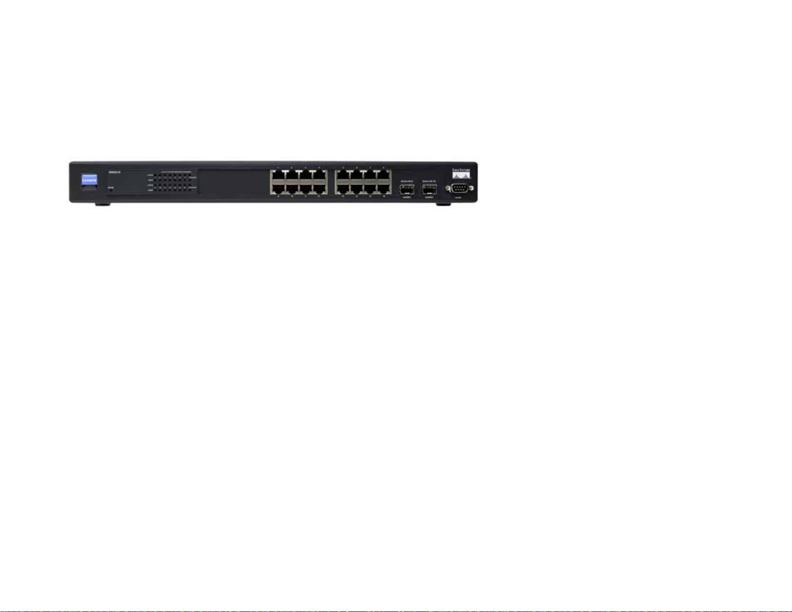
Chapter 2: Getting to Know the Switch
SRW2048
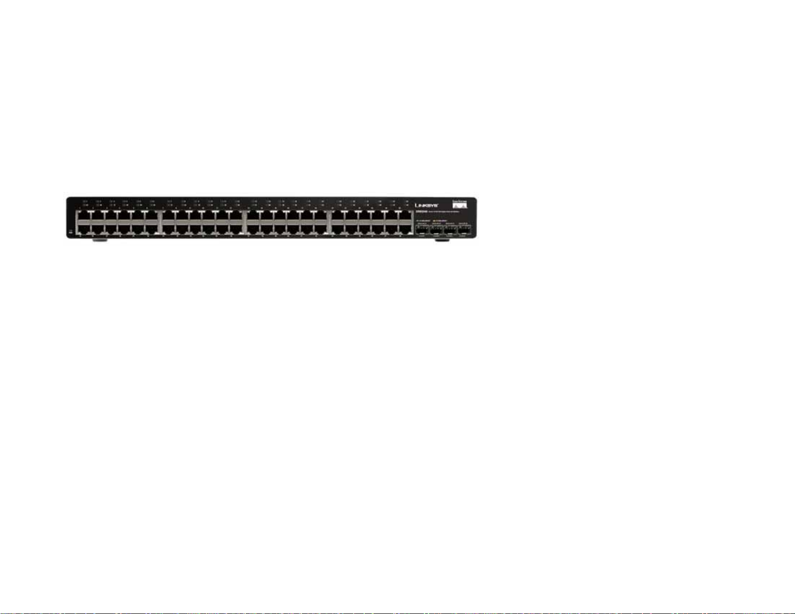
Front Panel
The Switch's LEDs and ports are located on the front panel.
LEDs
PWR Green. The PWR LED lights up to indicate that the Switch is powered on.
Link/Act (1-48) Green. The LED lights up green to indicate a functional 10/100Mbps network link through
the corresponding port (1 through 48) with an attached device. It flashes to indicate that
the Switch is actively sending or receiving data over that port.
Orange. The LED lights up orange to indicate a 1000Mbps connection on the corresponding
port (1 through 48) with an attached device. It flashes to indicate that the Switch is actively
sending or receiving data over that port.
Ports
1-48 The Switch is equipped with 48 auto-sensing, Ethernet network ports, which use RJ-45
connectors. The Fast Ethernet ports support network speeds of 10Mbps, 100Mbps, or
1000Mbps. They can operate in half and full-duplex modes. Auto-sensing technology
enables each port to automatically detect the speed of the device connected to it (10Mbps,
100Mbps, or 1000Mbps), and adjust its speed and duplex accordingly.
Figure 2-1: Front Panel of the SRW2048
5
Chapter 2: Getting to Know the Switch
SRW2048
WebView Switches
miniGBIC 1-4 The miniGBIC (gigabit interface converter) port is a connection point for a miniGBIC
expansion module, so the Switch can be uplinked via fiber to another switc h. The MiniGBIC
port provides a link to a high-speed network segment or individual workstation at speeds
of up to 1000Mbps.
Use the Linksys MGBT1, MGBSX1, or MGBLH1 miniGBIC modules with the Switch. The
MGBSX1 and the MGBLH1 require fiber cabling with LC connectors, while the MGBT1
requires a Category 5e Ethernet cable with an RJ-45 connector.
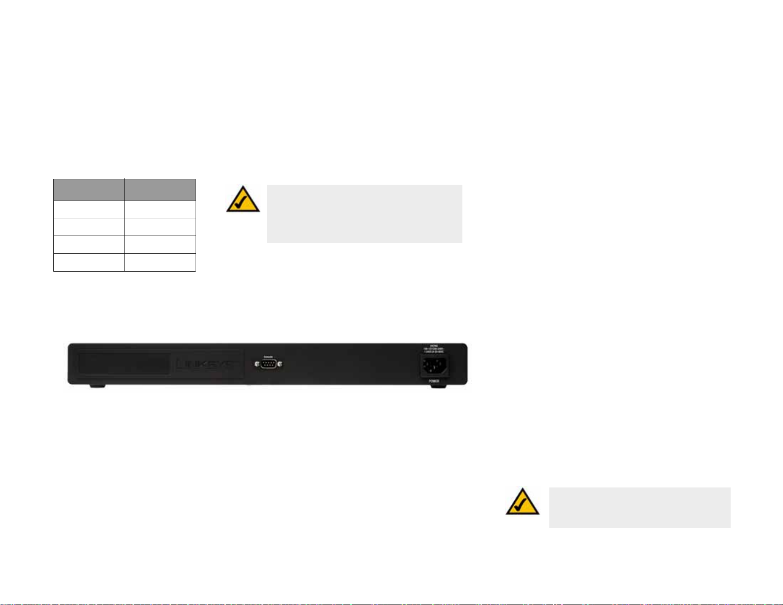
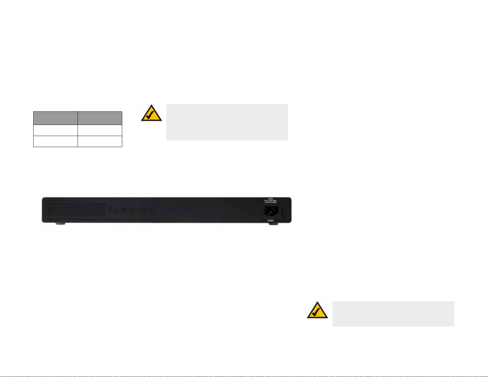
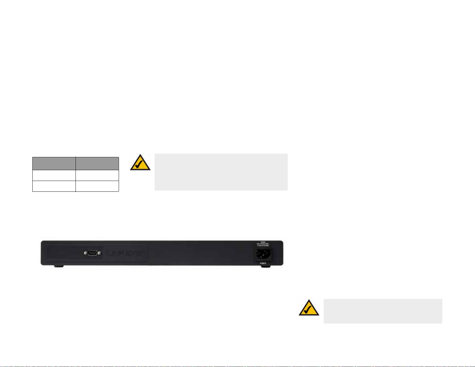
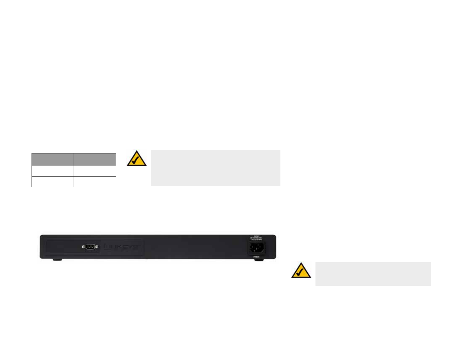
Back Panel
The power port is located on the back panel of the Switch.
Console The Console port is where you can connect a serial cable to a PC’s serial port for
configuration using your PC’s HyperTerminal program. Refer to Chapter 4: Using the
Console Interface for Configuration for more information.
Power The Power port is where you will connect the power cord.
Table 1: SRW2048 Shared Port Mapping
miniGBIC Port Standard Port
miniGBIC 1 Port 23
miniGBIC 2 Port 24
miniGBIC 3 Port 47
miniGBIC 4 Port 48
Figure 2-2: Back Panel of the SRW2048
NOTE: If you need to reset the Switch, unplug
the power cord from the back of the Switch.
Wait a few seconds and then reconnect it.
NOTE: On the SRW2048, MiniGBIC ports are shared
with standard ports. If a miniGBIC port is used, then
the shared standard port on the Switch cannot be
used. See "T able 1:SRW2048 Shared Port Mapping"
for port mapping details of the SRW2048 Switch.
6
Chapter 2: Getting to Know the Switch
SRW2024
WebView Switches
SRW2024
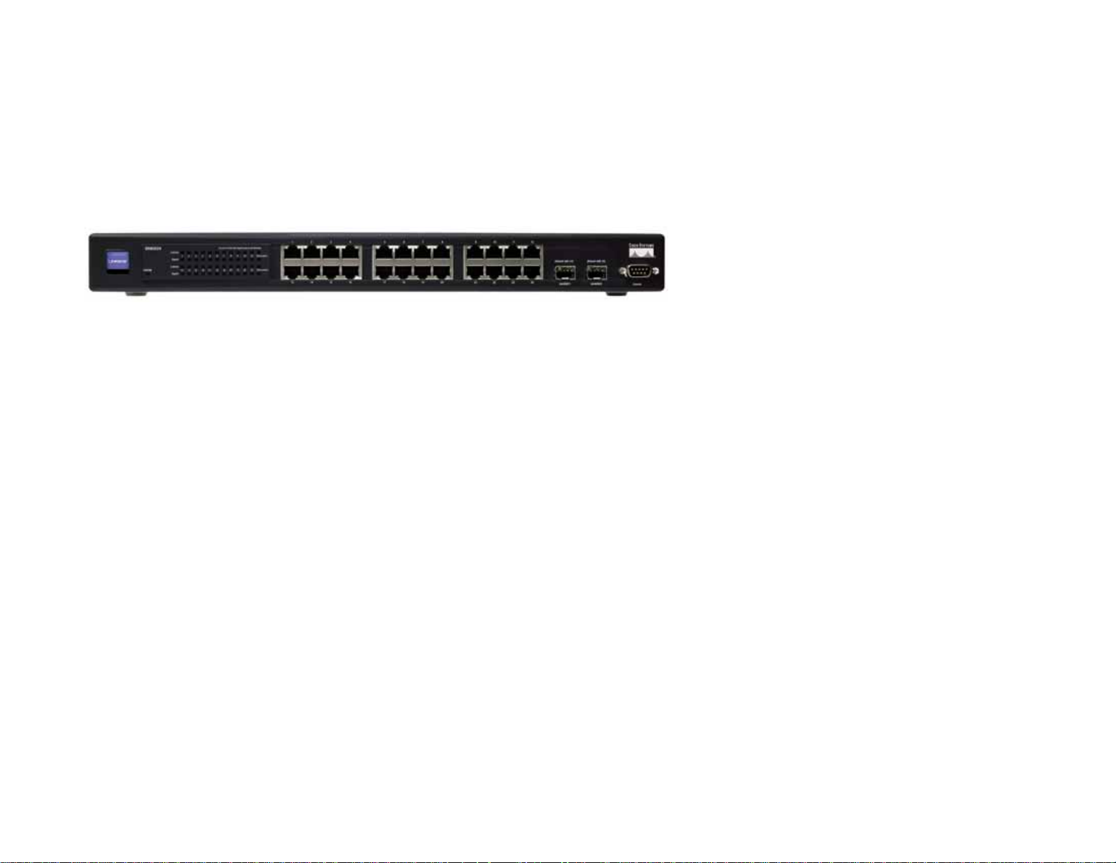
Front Panel
The Switch's LEDs and ports are located on the front panel.
LEDs
SYSTEM Green. The SYSTEM LED lights up to indicate that the Switch is powered on.
Link/Act (1-24) Green. The LED lights up green to indicate a functional 10/100Mbps network link through
the corresponding port (1 through 24) with an attached device. It flashes to indicate that
the Switch is actively sending or receiving data over that port.
Gigabit (1-24) Orange. The LED lights up orange to indicate a 1000Mbps connection on the corresponding
port (1 through 24) with an attached device.
Ports
1-24 The Switch is equipped with 24 auto-sensing, Ethernet network ports, which use RJ-45
connectors. The Fast Ethernet ports support network speeds of 10Mbps, 100Mbps, or
1000Mbps. They can operate in half and full-duplex modes. Auto-sensing technology
enables each port to automatically detect the speed of the device connected to it (10Mbps,
100Mbps, or 1000Mbps), and adjust its speed and duplex accordingly.
Figure 2-3: Front Panel of the SRW2024
7
Chapter 2: Getting to Know the Switch
SRW2024
WebView Switches
miniGBIC 1-2 The miniGBIC (gigabit interface converter) port is a connection point for a miniGBIC
expansion module, so the Switch can be uplinked via fiber to another switc h. The MiniGBIC
port provides a link to a high-speed network segment or individual workstation at speeds
of up to 1000Mbps.
Use the Linksys MGBT1, MGBSX1, or MGBLH1 miniGBIC modules with the Switch. The
MGBSX1 and the MGBLH1 require fiber cabling with LC connectors, while the MGBT1
requires a Category 5e Ethernet cable with an RJ-45 connector.
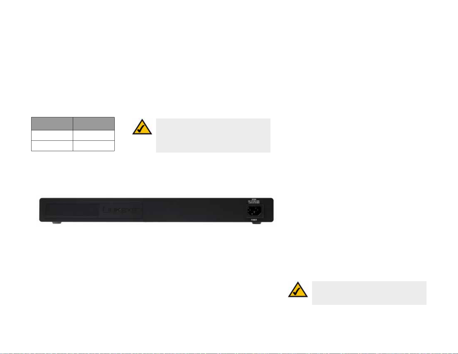
Back Panel
The power port is located on the back panel of the Switch.
Console The Console port is where you can connect a serial cable to a PC’s serial port for
configuration using your PC’s HyperTerminal program. Refer to Chapter 4: Using the
Console Interface for Configuration for more information.
Power The Power port is where you will connect the power cord.
Table 2: SRW2024 Shared Port Mapping
miniGBIC Port Standard Port
miniGBIC 1 Port 12
miniGBIC 2 Port 24
Figure 2-4: Back Panel of the SRW2024
NOTE: If you need to reset the Switch, unplug the
power cord from the back of the Switch. Wait a few
seconds and then reconnect it.
NOTE: On the SRW2024, MiniGBIC ports are shared
with standard ports. If a miniGBIC port is used, then
the shared standard port on the Switch cannot be
used. See "T able 1:SRW2024 Shared Port Mapping"
for port mapping details of the SRW2024 Switch.
8
Chapter 2: Getting to Know the Switch
SRW2016
WebView Switches
SRW2016
Front Panel
The Switch's LEDs and ports are located on the front panel.
LEDs
SYSTEM Green. The SYSTEM LED lights up to indicate that the Switch is powered on.
Link/Act (1-16) Green. The LED lights up green to indicate a functional 10/100Mbps network link through
the corresponding port (1 through 16) with an attached device. It flashes to indicate that
the Switch is actively sending or receiving data over that port.
Gigabit (1-16) Orange. The LED lights up orange to indicate a 1000Mbps connection on the corresponding
port (1 through 16) with an attached device.
Ports
1-16 The Switch is equipped with 16 auto-sensing, Ethernet network ports, which use RJ-45
connectors. The Fast Ethernet ports support network speeds of 10Mbps, 100Mbps, or
1000Mbps. They can operate in half and full-duplex modes. Auto-sensing technology
enables each port to automatically detect the speed of the device connected to it (10Mbps,
100Mbps, or 1000Mbps), and adjust its speed and duplex accordingly.
Figure 2-5: Front Panel of the SRW2016
9
Chapter 2: Getting to Know the Switch
SRW2016
WebView Switches
miniGBIC 1-2 The miniGBIC (gigabit interface converter) port is a connection point for a miniGBIC
expansion module, so the Switch can be uplinked via fiber to another switc h. The MiniGBIC
port provides a link to a high-speed network segment or individual workstation at speeds
of up to 1000Mbps.
Use the Linksys MGBT1, MGBSX1, or MGBLH1 miniGBIC modules with the Switch. The
MGBSX1 and the MGBLH1 require fiber cabling with LC connectors, while the MGBT1
requires a Category 5e Ethernet cable with an RJ-45 connector.
The Back Panel
The power port is located on the back panel of the Switch.
Console The Console port is where you can connect a serial cable to a PC’s serial port for
configuration using your PC’s HyperTerminal program. Refer to Chapter 4: Using the
Console Interface for Configuration for more information.
Power The Power port is where you will connect the power cord.
Table 3: SRW2016 Shared Port Mapping
miniGBIC Port Standard Port
miniGBIC 1 Port 8
miniGBIC 2 Port 16
Figure 2-6: Back Panel of the SRW2016
NOTE: If you need to reset the Switch, unplug the
power cord from the back of the Switch. Wait a few
seconds and then reconnect it.
NOTE: On the SRW2016, MiniGBIC ports are shared
with standard ports. If a miniGBIC port is used, then
the shared standard port on the Switch cannot be
used. See "T able 1:SRW2016 Shared Port Mapping"
for port mapping details of the SRW2016 Switch.
10
Chapter 2: Getting to Know the Switch
SRW248G4
WebView Switches
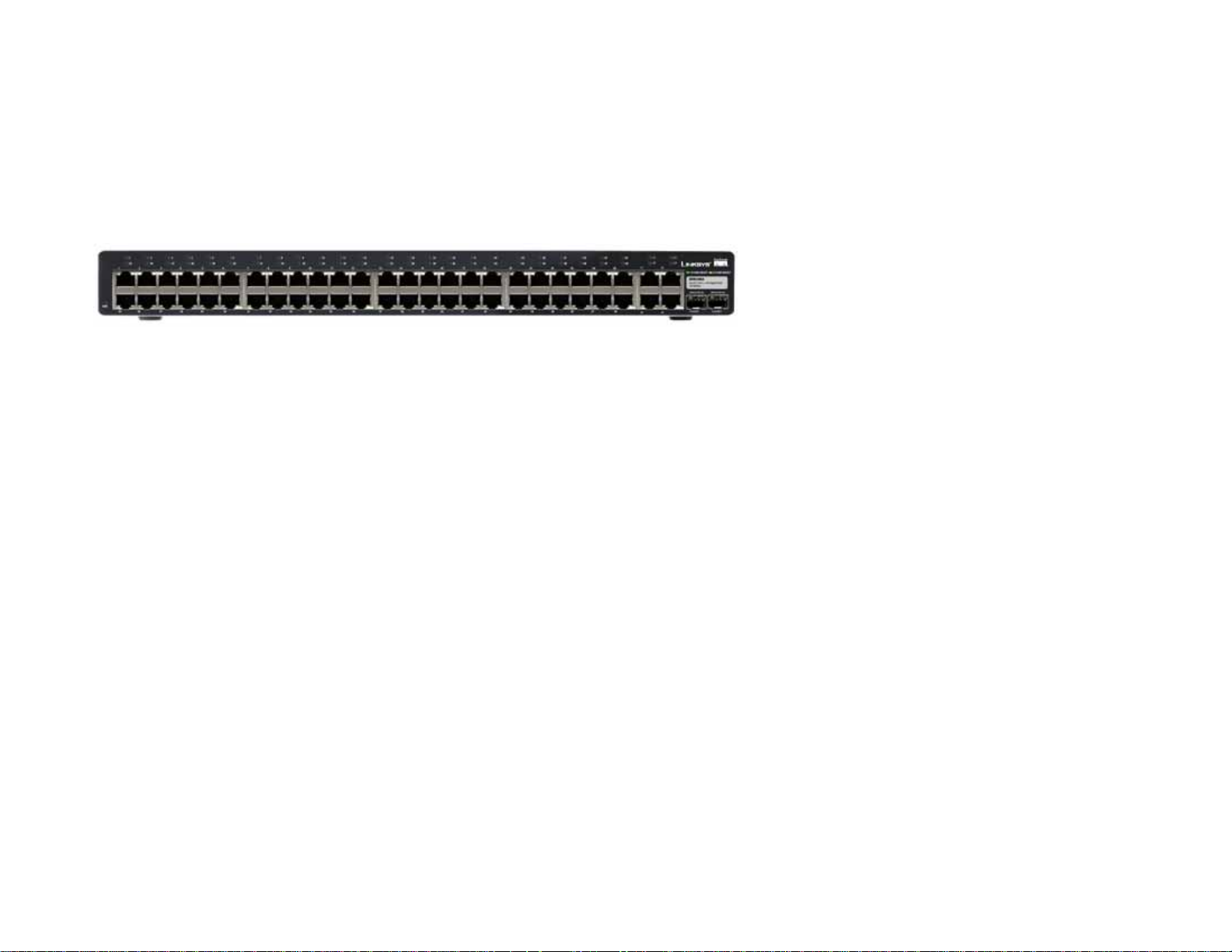
SRW248G4
Front Panel
The Switch's LEDs and ports are located on the front panel.
LEDs
PWR Green. The PWR LED lights up to indicate that the Switch is powered on.
Link/Act (1-48) Green. The LED lights up green to indicate a functional 10/100Mbps network link through
the corresponding port (1 through 48) with an attached device. It flashes to indicate that
the Switch is actively sending or receiving data over that port.
Link/Act (G1-G4) Green. The LED lights up green to indicate a functional 10/100Mbps network link through
the corresponding port (G1 through G4) with an attached device. It flashes to indicate that
the Switch is actively sending or receiving data over that port.
Orange. The LED lights up orange to indicate a 1000Mbps connection on the corresponding
port (G1 through G4) with an attached device. It flashes to indicate that the Switch is
actively sending or receiving data over that port.
Ports
1-48 The Switch is equipped with 48 auto-sensing Ethernet network ports, which use RJ-45
connectors. The Fast Ethernet ports support network speeds of 10Mbps or 100Mbps. They
can operate in half and full-duplex modes. Auto-sensing technology enables each port to
automatically detect the speed of the device connected to it (10Mbps or 100Mbps), and
adjust its speed and duplex accordingly.
Figure 2-7: Front Panel of the SRW248G4
11
Chapter 2: Getting to Know the Switch
SRW248G4
WebView Switches
G1-G4 The Switch is equipped with 4 auto-sensing Gigabit Ethernet network ports, which use
RJ-45 connectors. The Gigabit Ethernet ports support network speeds of 10Mbps,
100Mbps, or 1000Mbps. They can operate in half and full-duplex modes. Auto-sensing
technology enables each port to automatically detect the speed of the device connected to
it (10Mbps, 100Mbps, or 1000Mbps), and adjust its speed and duplex accordingly.
miniGBIC 1-2 The miniGBIC (gigabit interface converter) port is a connection point for a miniGBIC
expansion module, so the Switch can be uplinked via fiber to another switc h. The MiniGBIC
port provides a link to a high-speed network segment or individual workstation at speeds
of up to 1000Mbps.
Use the Linksys MGBT1, MGBSX1, or MGBLH1 miniGBIC modules with the Switch. The
MGBSX1 and the MGBLH1 require fiber cabling with LC connectors, while the MGBT1
requires a Category 5e Ethernet cable with an RJ-45 connector.
Back Panel
The power port is located on the back panel of the Switch.
Console The Console port is where you can connect a serial cable to a PC’s serial port for
configuration using your PC’s HyperTerminal program. Refer to Chapter 4: Using the
Console Interface for Configuration for more information.
Power The Power port is where you will connect the power cord.
Table 4: SRW248G4 Shared Port
Mapping
miniGBIC Port Gigabit Port
miniGBIC 1 Port G3
miniGBIC 2 Port G4
Figure 2-8: Back Panel of the SRW248G4
NOTE: If you need to reset the Switch, unplug the
power cord from the back of the Switch. Wait a few
seconds and then reconnect it.
NOTE: On the SRW248G4, MiniGBIC ports are shared with
Gigabit Ethernet ports. If a miniGBIC port is used, then the
shared Gigabit Ethernet port on the Switch cannot be
used. See "Table 1:SRW248G4 Shared Port Mapping" for
port mapping details of the SRW248G4 Switch.

12
Chapter 2: Getting to Know the Switch
SRW224G4
WebView Switches
SRW224G4
Front Panel
The Switch's LEDs and ports are located on the front panel.
LEDs
PWR Green. The PWR LED lights up to indicate that the Switch is powered on.
Link/Act (1-24) Green. The LED lights up green to indicate a functional 10/100Mbps network link through
the corresponding port (1 through 16) with an attached device. It flashes to indicate that
the Switch is actively sending or receiving data over that port.
Link/Act (G1-G4) Green. The LED lights up green to indicate a functional 10/100Mbps network link through
the corresponding port (G1 through G4) with an attached device. It flashes to indicate that
the Switch is actively sending or receiving data over that port.
1000Mbps (G1-G4) Orange. The LED lights up orange to indicate a 1000Mbps connection on the corresponding
port (G1 through G4) with an attached device.
Ports
1-24 The Switch is equipped with 24 auto-sensing, Ethernet network ports, which use RJ-45
connectors. The Fast Ethernet ports support network speeds of 10Mbps, 100Mbps, or
1000Mbps. They can operate in half and full-duplex modes. Auto-sensing technology
enables each port to automatically detect the speed of the device connected to it (10Mbps,
100Mbps, or 1000Mbps), and adjust its speed and duplex accordingly.
Figure 2-9: Front Panel of the SRW224G4
13
Chapter 2: Getting to Know the Switch
SRW224G4
WebView Switches
G1-G4 The Switch is equipped with 4 auto-sensing Gigabit Ethernet network ports, which use RJ-
45 connectors. The Gigabit Ethernet ports support network speeds of 10Mbps, 100Mbps,
or 1000Mbps. They can operate in half and full-duplex modes. Auto-sensing technology
enables each port to automatically detect the speed of the device connected to it (10Mbps,
100Mbps, or 1000Mbps), and adjust its speed and duplex accordingly.
miniGBIC 1-2 The miniGBIC (gigabit interface converter) port is a connection point for a miniGBIC
expansion module, so the Switch can be uplinked via fiber to another switc h. The MiniGBIC
port provides a link to a high-speed network segment or individual workstation at speeds
of up to 1000Mbps.
Use the Linksys MGBT1, MGBSX1, or MGBLH1 miniGBIC modules with the Switch. The
MGBSX1 and the MGBLH1 require fiber cabling with LC connectors, while the MGBT1
requires a Category 5e Ethernet cable with an RJ-45 connector.
Back Panel
The power port is located on the back panel of the Switch.
Console The Console port is where you can connect a serial cable to a PC’s serial port for
configuration using your PC’s HyperTerminal program. Refer to Chapter 4: Using the
Console Interface for Configuration for more information.
Power The Power port is where you will connect the power cord.
Table 5: SRW224G4 Shared Port
Mapping
miniGBIC Port Gigabit Port
miniGBIC 1 Port G3
miniGBIC 2 Port G4
Figure 2-10: Back Panel of the SRW224G4
NOTE: If you need to reset the Switch, unplug the
power cord from the back of the Switch. Wait a few
seconds and then reconnect it.
NOTE: On the SRW224G4, MiniGBIC ports are shared with
Gigabit Ethernet ports. If a miniGBIC port is used, then the
shared Gigabit Ethernet port on the Switch cannot be
used. See "Table 1:SRW224G4 Shared Port Mapping" for
port mapping details of the SRW224G4 Switch.
14
Chapter 3: Connecting the Switch
Overview
WebView Switches
Chapter 3: Connecting the Switch
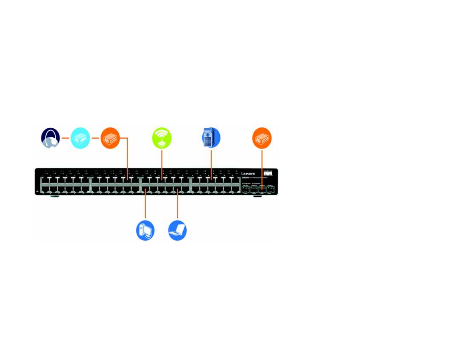
Overview
This chapter will explain how to connect network devices to the Switch. For an example of a typical network
configuration, see the application diagram shown below.
Cable/DSL
Modem
Router
Internet
Wireless
Access Point
Uplink via Fiber
to Switch
Server
Figure 3-1: Typical Network Configuration for the SRW2048
10/100/1000
Desktop
10/100
Notebook

15
Chapter 3: Connecting the Switch
Before You Install the Switch...
WebView Switches
When you connect your network devices, make sure you don’t exceed the maximum cabling distances, which are
listed in the following table:
*A hub refers to any type of 100Mbps hub, including regular hubs and stackable hubs. A 10Mbps hub connected
to another 10Mbps hub can span up to 100 meters (328 feet).
Before You Install the Switch...
When you choose a location for the Switch, observe the following guidelines:
• Make sure that the Switch will be accessible and that the cables can be easily connected.
• Keep cabling away from sources of electrical noise, power lines, and fluorescent lighting fixtures.
• Position the Switch away from water and moisture sources.
• To ensure adequate air flow around the Switch, be sure to provide a minimum clearance of two inches
(50 mm).
• Do not stack free-standing Switches more than four units high.
Table 1: Maximum Cabling Distances
From To Maximum Distance
Switch Switch or Hub* 100 meters (328 feet)
Hub Hub 5 meters (16.4 feet)
Switch or Hub Computer 100 meters (328 feet)
16
Chapter 3: Connecting the Switch
Placement Options
WebView Switches
Placement Options
Before connecting cables to the Switch, first you will physically install the Switch. Either set the Switch on its four
rubber feet for desktop placement or mount the Switch in a standard-sized, 19-inch wide, 1U high rack for rack-
mount placement.
Desktop Placement
1. Attach the rubber feet to the recessed areas on the bottom of the Switch.
2. Place the Switch on a desktop near an AC power source.
3. Keep enough ventilation space for the Switch and check the environmental restrictions mentioned in the
specifications.
4. Proceed to the section, “Connecting the Switch.”
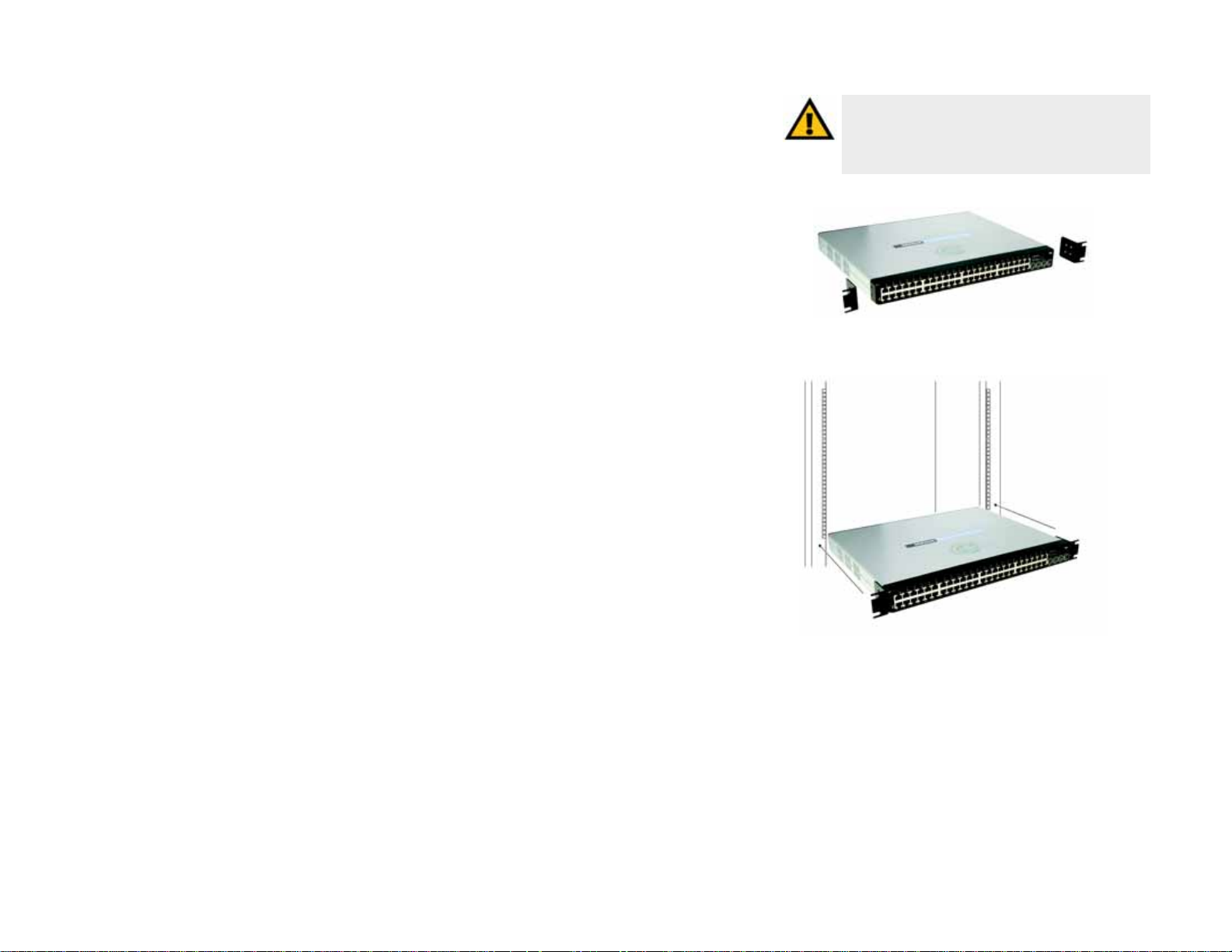
Rack-Mount Placement
To mount the Switch in any standard-sized, 19-inch wide, 1U high rack, follow these instructions:
1. Place the Switch on a hard flat surface with the front panel facing you.
2. Attach a rack–mount bracket to one side of the Switch with the supplied screws. Then attach the other
bracket to the other side.
3. Make sure the brackets are properly attached to the Switch.
4. Use the appropriate screws (not included) to securely attach the brackets to your rack.
Proceed to the section, “Connecting the Switch.”
IMPORTANT: Make sure you use the screws
supplied with the mounting brackets. Using the
wrong screws could damage the Switch and would
invalidate your warranty.
Figure 3-3: Mount the Switch in the Rack
Figure 3-2: Attach the Brackets to the Switch
17
Chapter 3: Connecting the Switch
Connecting the Switch
WebView Switches
Connecting the Switch
To connect network devices to the Switch, follow these instructions:
1. Make sure all the devices you will connect to the Switch are powered off.
2. For 10/100Mbps devices, connect a Category 5 Ethernet network cable to one of the numbered ports on the
Switch. For a 1000Mbps device, connect a Category 5e Ethernet network cable to one of the numbered ports
on the Switch.
3. Connect the other end to a PC or other network device.
4. Repeat steps 2 and 3 to connect additional devices.
5. If you are using the miniGBIC port, then connect the miniGBIC module to the miniGBIC port. For detailed
instructions, refer to the module’s documentation.
6. If you will use the Switch’s console interface to configure the Switch, then connect the supplied serial cable
to the Switch’s Console port, and tighten the captive retaining screws. Connect the other end to your PC’s
serial port. (This PC must be running the VT100 terminal emulation software, such as HyperTerminal.)
7. Connect the supplied power cord to the Switch’s power port, and plug the other end into an electrical outlet.
8. Power on the network devices connected to the Switch. Each active port’s corresponding Link/Act LED will
light up on the Switch. If a port has an active Gigabit connection, then its corresponding Gigabit LED will also
light up.
If you will use the Switch’s console interface to configure the Switch, proceed to Chapter 4: Using the
Console Interface for Configuration for directions.
If you will use the Switch’s Web-based Utility to configure the Switch, proceed to Chapter 5: Using the
Web-based Utility for Configuration.
NOTE: If you need to reset the Switch, unplug the
power cord from the back of the Switch. Wait a
few seconds and then reconnect it.
IMPORTANT: Make sure you use the power cord that is supplied with the Switch. Use of a
different power cord could damage the Switch.
18
Chapter 4: Using the Console Interface for Configuration
Overview
WebView Switches
Chapter 4: Using the Console Interface for Configuration
Overview
The Switch features a menu-driven console interface for basic configuration of the Switch and management of
your network. The Switch can be configured using CLI through the console interface or through a telnet
connection. This chapter describes console interface configuration. Configuration can also be performed through
the web utility, which is covered in the next chapter.
Configuring the HyperTerminal Application
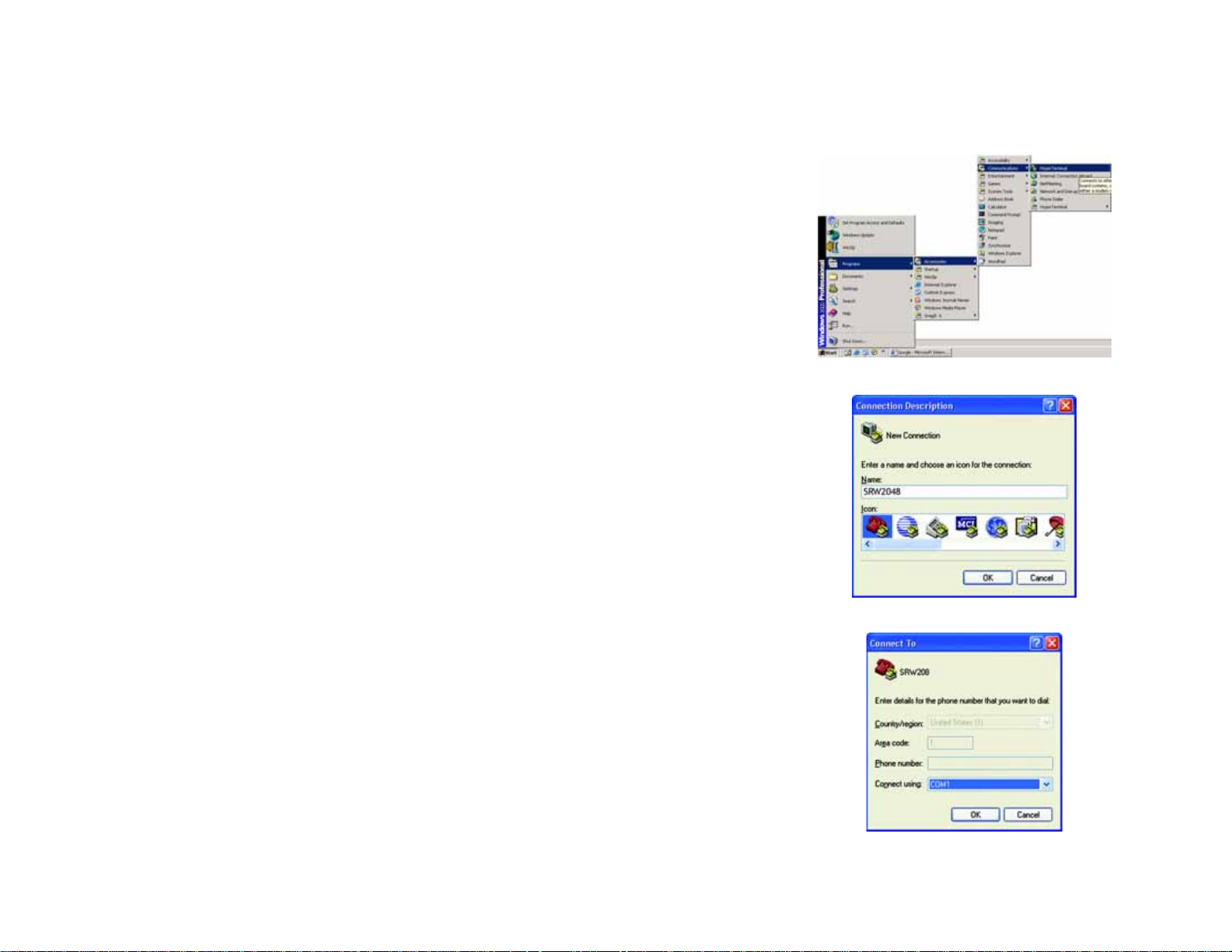
Before you use the console interface, you will need to configure the HyperTerminal application on your PC.
1. Click the Start button. Select Programs and choose Accessories. Select Communications. Select
HyperTerminal from the options listed in this menu.
2. On the Connection Description screen, enter a name for this connection. In the example, the name of
connection is SRW2048. Select an icon for the application. Then, click the OK button.
3. On the Connect To screen, select a port to communicate with the Switch: COM1, COM2, or TCP/IP.
Figure 4-2: Connection Description
Figure 4-1: Finding HyperTerminal
Figure 4-3: Connect To

19
Chapter 4: Using the Console Interface for Configuration
Connecting to the Switch through a Telnet Session
WebView Switches
4. Set the serial port settings as follows:
Bits per second: 38400
Data bits: 8
Parity: None
Stop bits: 1
Flow control: None
Then, click the OK button.
Connecting to the Switch through a Telnet Session
Open a command line editor and enter telnet 192.168.1.254. Then, press the Enter key.
The Login screen will now appear. The first time you open the CLI interface, select Edit and hit Enter. Enter admin
in the User Name field. Leave the Password field blank.
Press the Esc button and you will return to the login screen. Use the right arrow button to navigate to Execute
and press the Enter button to enter the CLI interface.
Figure 4-4: COM1 Properties
Figure 4-5: Telnet Login screen

20
Chapter 4: Using the Console Interface for Configuration
Configuring the Switch through the Console Interface
WebView Switches
Configuring the Switch through the Console Interface
The console screens consist of a series of menus. Each menu has several options, which are listed vertically. You
select a menu option when you highlight it; pressing the Enter key activates the highlighted option.
T o navigate through the menus and actions of the console interface, use the up or down arrow keys to move up or
down, and use the left or right arrow keys to move left or right. Use the Enter key to select a menu option, and use
the Esc key to return to the previous selection. Menu options and any values entered or present will be
highlighted. The bottom of the screen lists the actions available.
Switch Main Menu
The System Main Menu screen displays these choices:
1. System Configuration Information Menu
2. Port Status
3. Port Configuration
4. Help
0. Logout
Figure 4-6: Switch Main Menu
Loading...