


 Loading...
USER’S GUIDE |
|
|
Logic 4 |
H, J, AND HJ |
T AND APT |
L3
GH |
|
GT |
|
|
|
THIS PRODUCT IS TO BE INSTALLED AND SERVICED BY A TRAINED DOOR SYSTEMS TECHNICIAN ONLY.
Operators are shipped in C2 operating mode.
Visit www.liftmaster.com to locate a professional installing dealer in your area.
2 YEAR WARRANTY
Serial # Box
Installation Date
CONTACT INFORMATION |
THIS OPERATOR FEATURES THE ENHANCED |
|
|
EN |
|
|
|
||
|
|
T |
A |
|
|
|
|
|
|
M |
|
|
|
||
|
|
|
|
A |
|
PATENT PENDING |
|
R |
S |
|
T SY |
M
The Maintenance Alert System™ allows the installer to set an internal Maintenance Cycle Counter. The Logic 4 operator incorporates a self-diagnostic feature built into the (MAS) Maintenance Alert System LED. An LED on the 3-button station will signal when the set number of cycles/months is reached or when the operator requires immediate service.
NOT FOR RESIDENTIAL USE
315MHz
Radio Receiver Built on Board
www.liftmaster.com
INTRODUCTION
Congratulations on purchasing a quality, LiftMaster Logic 4 Commercial Door Operator. Your new operator is capable of operating up to 12 cycles per hour or 50 cycles per day. It is equipped with a built in radio receiver that is compatible with our existing 315 MHz product line as well as a Timer-to-Close (TTC) feature that can be enabled when LiftMaster Commercial Protector System® is installed and aligned properly.
BASIC PROGRAMMING
INTRODUCTION TO PROGRAMMING
Many programmable functions require that a LiftMaster Entrapment Protection (LMEP) device be installed in order to function. Refer to the Entrapment Protection section.
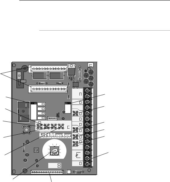
LOGIC BOARD OVERVIEW
Optional Auxiliary
Card Receptacles
Motor Direction Jumper
Maximum Run
Timer Button
Radio Learn Button
Mid Stop Learn Button
Timer-To-Close
Learn Button
SLOT |
1 |
SLOT |
24VAC |
2 |
POWER |
24VAC |
|
|
|
|
|
|
|
|
TIMER |
|
|
OLS |
|
|
|
|
|
DEFEAT |
STD |
REV |
|
|
|
-1 |
-3 |
|
|
|
|
|
|
COMMON |
||||
MOTOR DIRECTION |
MID |
|
|
|
PHASE |
PHASE |
MAS |
|
|
|
|
|
|
|
|
|
|
|
|
SLS |
|
|
|
|
|
|
|
|
CLS |
|
|
|
|
|
LMEP: |
|
|
|
|
|
|
|
|
|
|
|
|
MRT |
MID |
TTC |
TIMER |
EDGE: |
|
|
|
|
|
|
|
ENABLE |
||
|
|
|
|
|
|
|
||
|
|
|
|
|
|
|
|
OPEN |
|
|
RADIO |
1 |
2 |
3 |
|
|
|
CLOSE |
|
STOP |
T |
TS |
E2 |
|
FSTS |
|
D1 |
|
DIAG |
COMMON |
|
|
|
|
C2 |
|
OPTN |
|
B2 |
|
PROG |
|
|
|
|
|
RELAY |
A |
|
SBC |
|
|
||
RELAY |
B |
|
|
DATA |
Single Phase &
Three Phase Jumper
Maintenance Alert System Button for Programming
Open Button
Close Button
Stop Button
Control Wiring
Terminal Block
Selector Dial
(used for programming Main Motor Control Harness Connection and selecting wiring type)
LOGIC BOARD LED OVERVIEW
NOTE: Before programming the logic board, set the operator’s open and close limits. LEDs on the logic board are provided to assist setting the limits. As each limit is activated the corresponding LED will light up. The abbreviations are Open Limit Switch (OLS), Close Limit Switch (CLS) and Sensing Limit Switch (SLS). Refer to page 19 for limit switch adjustment instructions.
When power is applied to the operator, the following LED’s will illuminate: STOP, CLOSE, OPEN, LMEP, 24Vac, RADIO, DATA, TIMER ENABLE, OLS MID, SLS, CLS, and MAS. Once the power up process is completed (approximately 2-3 seconds) only the appropriate LED’s will continue to be lit (i.e., STOP, 24Vdc, limit LED(s) if limit(s) is activated).
NOTE: When the power up process is over, the MAS LED will blink a code indicating the version of firmware. If the selector dial is in the DIAG, OPTN, or PROG position, the MAS will not provide this code. After the code has been provided the MAS LED will go out.
LOGIC BOARD PUSH BUTTONS (OPEN, CLOSE, STOP)
Open, Close and Stop buttons are mounted directly on the logic board. Thus, making it easy to program as well as have door control at the electrical box.
Either the stop control or a jumper MUST be wired between terminals 4 and 5 for the on board push buttons to function.
2

BASIC PROGRAMMING
DETERMINE AND SET WIRING TYPE
Read the descriptions of the different wiring types to determine which setting will be correct for each application. Once the wiring type is determined, set the selector dial accordingly.
LIFTMASTER MONITORED ENTRAPMENT PROTECTION (LMEP) DEVICE IS REQUIRED
A LiftMaster Entrapment Protection (LMEP) device is required for the following wiring types.
B2 Momentary contact to open, close and stop, plus wiring for sensing device to reverse and auxiliary devices to open and close with open override. Programmable mid stop available with this wiring type. Compatible with 3-Button Station,
1-Button Station, 1 and 3-Button Remote Control. TS (TIMER SECURE)
This mode will attempt to close the door from any position except when fully closed, or when a safety input is present. The stop button will not disable the Timer-To-Close at any position. To disable the Timer-To-Close in this mode, installation of a defeat switch is required (see wiring diagram).
Momentary contact to open, close, and stop with open override and Timer-To-Close. Every device that causes door to open, including a reversing device, activates the Timer- To-Close. Auxiliary controls can be connected to open input to activate the Timer-To-Close. If the timer has been activated, the open button and radio control can recycle the timer. The Timer-To-Close will function from the programmable mid stop with this wiring type. Compatible with 3-Button Station, 1-Button Station and 1 and 3-Button Remote Control.
NOTE: A Programmable “Car Dealer Mode” available.
TMomentary contact to open, close, and stop, with open override and Timer-To-Close. Every device that causes the door to open, except any safety edge input device, activates the Timer-To-Close. Auxiliary controls can be connected to open input to activate the Timer-To-Close. If the Timer-To- Close has been activated, the open button and radio control can recycle the timer. The stop button will deactivate the timer until the next command input. The Timer-To-Close will function from the programmable mid stop with this wiring type. Compatible with 3-Button Station,1-Button Station and 1 and 3-Button Remote Control.
NOTE: Programmable “Car Dealer Mode” available.
FSTS Momentary button contact for open, close and stop programming. User set mid stop. User set Timer-To-Close. The single button station opens the door to the full open limit bypassing the mid stop and activates the Timer-To- Close, putting the operator in TS mode until the door reaches the down limit, or is stopped in travel. At which time the operator enters the B2 mode.
Compatible with 3-Button Station, 1-Button Station, 1 and 3-Button Remote Control. A 1-Button remote control in
FSTS mode will open only with the Timer-To-Close, bypassing a programmed mid stop. The Timer-To-Close will reset and reverse when closing.
LIFTMASTER MONITORED ENTRAPMENT PROTECTION (LMEP) DEVICE IS RECOMMENDED
A LiftMaster Entrapment Protection (LMEP) device is recommended for the following wiring types.
C2 Momentary contact to open and stop with constant pressure to close, open override plus wiring for sensing device to reverse. Programmable mid stop available with this wiring type. Compatible with 3-Button Station and 1-Button
Station.
E2 Momentary contact to open with override and constant pressure to close. Release of close button will cause door to reverse (roll-back feature) plus wiring for sensing device to reverse. Compatible with 3-Button Station.
D1 Constant pressure to open and close with wiring for sensing device to stop. Compatible with 2 or 3-Button Station.
SELECTOR DIAL
T TS
E2
FSTS
D1
 DIAG
DIAG
C2 |
OPTN |
B2 

 PROG
PROG
IMPORTANT NOTES:
1.External interlocks may be used with all functional modes.
2.Auxiliary devices are any devices that have only dry contacts. Examples: photocell, loop detector, pneumatic or electrical treadles, radio controls, one button stations, pull cords, etc.
3.Open override means that the door may be reversed while closing by activating an opening device without the need to use the stop button first.
4.When the door is in a stopped position other than fully closed, and a safety input is activated (LMEP or EDGE), the Restricted Close (RC) feature will allow a close command when the close button is pressed and held. The operator will begin closing after 5 seconds. If the close button is released the door will stop.
When in E2 mode, the door will move to the fully open position.
3
BASIC PROGRAMMING
 WARNING
To prevent possible SEVERE INJURY or DEATH:
•Install a LiftMaster Monitored Entrapment Protection (LMEP) device.
•NEVER permit children to operate or play with door control push buttons or remote controls.
•Activate door ONLY when it can be seen clearly, is properly adjusted and there are no obstructions to door travel.
•ALWAYS keep door in sight until completely closed. NEVER permit anyone to cross the path of closing door.
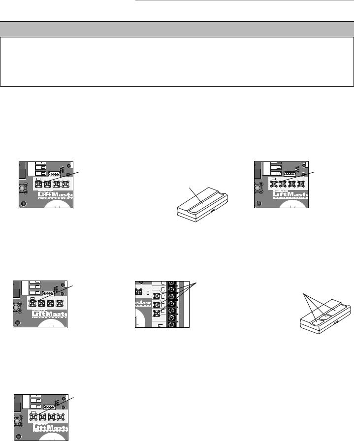
REMOTE CONTROLS
Built in 3-channel, 315 MHz radio receiver allows you to add as many as 23 Security ® remotes or dip switch remote controls.
NOTE: The following programming requires a LiftMaster Monitored Entrapment Protection (LMEP) device.
SINGLE BUTTON REMOTE CONTROL
1 |
MOTOR DIRECTION |
MID |
|
|
|
ASE |
Press and release the |
CLS |
|
|
|
LED will light). |
|||
|
SLS |
|
|
|
|
RADIO button (RADIO |
|
|
|
|
MRT |
MID |
TTC |
TI |
|
|
|
|
|
|
|
EN |
|
|
|
RADIO |
1 |
2 |
3 |
|
|
|
|
|
|
T |
TS |
|
|
|
|
|
E2 |
|
FSTS |
|
|
2 |
Press and hold the remote control button until the |
RADIO LED flashes rapidly, then release remote |
control button. The RADIO LED will then remain on solid after releasing the button. Repeat to add additional remote control(s).
3 |
MOTOR DIRECTION |
MID |
|
|
|
ASE |
SLS |
|
|
|
|||
|
CLS |
|
|
|
||
|
|
|
|
|
|
|
|
|
|
MRT |
MID |
TTC |
TI |
|
|
|
|
|
|
EN |
|
|
RADIO |
1 |
2 |
3 |
|
T TS
E2 |
FSTS |
Press and release the RADIO button to complete the programming. The programming mode
is exited if no activity is performed within 30 seconds.
3-BUTTON REMOTE CONTROL TO OPERATE AS A WIRELESS 3-BUTTON CONTROL STATION |
||||||||||||
NOTE: The feature will use 3 of the 23 memory channels in the operator. |
|
3 Press and hold the desired button of the remote |
||||||||||
1 |
|
SLS |
|
|
|
|
Press and release |
2 TTC |
TIMER |
EDGE: |
Press and release |
|
|
MOTOR DIRECTION |
MID |
|
|
|
ASE |
|
|
|
LMEP: |
|
|
|
|
|
|
|
the RADIO button |
3 |
ENABLE |
OPEN |
the desired button |
control until Radio LED flashes rapidly, then |
||
|
|
CLS |
|
|
|
|
on the logic board |
|
|
on the logic board |
release. |
|
|
|
|
MRT |
MID |
TTC |
TI |
(the Radio LED |
|
|
|
(OPEN, CLOSE or |
|
|
|
|
|
|
|
EN |
|
|
CLOSE |
STOP). The Radio |
|
|
|
|
|
|
|
|
|
will light). |
|
|
|
|
|
|
|
RADIO |
1 |
2 |
3 |
|
|
|
|
LED will flash and |
|
|
|
|
|
|
|
|
STOP |
|
|||||
|
|
|
|
|
|
|
|
|
|
|
||
|
|
|
|
|
|
|
|
FSTS |
|
|
then stay on solid. |
|
COMMON
 DIAG
DIAG
T |
TS |
E2 |
OPTN |
FSTS |
Repeat steps 1 through 3 to program additional buttons.
TO ERASE ALL REMOTE CONTROLS
1 |
MOTOR DIRECTION |
MID |
|
|
|
ASE |
Press and hold the |
|
|
|
|
||||
|
SLS |
|
|
|
RADIO button on the |
||
|
|
|
|
|
|
||
|
|
CLS |
|
|
|
|
logic board until the |
|
|
|
MRT |
MID |
TTC |
TI |
RADIO LED flashes |
|
|
|
|
|
|
EN |
rapidly (approximately |
|
|
|
|
|
|
|
|
|
|
RADIO |
1 |
2 |
3 |
|
5 seconds). |
|
|
|
|
|
|
|
|
|
|
|
|
|
|
|
All remote controls |
|
|
|
|
|
|
|
will be erased. |
TTS
E2 |
FSTS |
4
Loading...