


|
© KROHNE 08/2004 |
7.02140.35.00 |
|
|
|
|
|
|
|
|
|
|
|
|
|
|
|
||
|
|
|
|
|
|
|
|
||
|
|
|
|
|
|
|
|
|
|
|
|
|
|
|
|
|
|
|
|
|
GR |
|
|
|
|
|
|
|
|
Condensed Instructions
IFC 010 C
IFC 010 W
Signal converters for
OPTIFLUX flowmeters
PLEASE NOTE
These concise instructions do not include the following: device description, technical data, standards, approvals, etc., nor conditions pertaining to product liability and warranty.
The operator is, however, obligated to take note of these sections in the detailed Installation and Operating Instructions.
Subject to change without notice.
Applicable to
Software-Versions
●IFC 010 _ / D Display version No. 806325.07 and
No. 317551.02 and higher
●IFC 010 _ / B Basic version
operator-controllable HHT 010
No. 806323.06 and higher
Variable area flowmeters
Vortex flowmeters
Flow controllers
Electromagnetic flowmeters
Ultrasonic flowmeters
Mass flowmeters
Level measuring instruments
Communications technology
Engineering systems & solutions
Switches, counters, displays and recorders
Heat metering
Pressure and temperature

Contents |
|
|
|
|
1 |
Electrical connection: power supply............................................................................................................................................. |
|
3 |
|
1.1 |
Important installation notes ............................................................................................................................................................... |
|
3 |
|
1.1.1 |
Location............................................................................................................................................................................................. |
|
|
3 |
1.1.2 |
Only for separate systems/signal converters |
(W versions) .............................................................................................................. |
3 |
|
1.1.3 |
Cable entries ..................................................................................................................................................................................... |
|
|
3 |
1.2 |
Connection to power ......................................................................................................................................................................... |
|
|
4 |
1.3 |
Electrical connection of separate flow sensor |
(W Versions) ............................................................................................................ |
5 |
|
1.3.1 |
General information on signal cable A and field current cable C ...................................................................................................... |
5 |
||
1.3.2 |
Grounding of flow sensor .................................................................................................................................................................. |
|
5 |
|
1.3.3 |
Cable preparation.............................................................................................................................................................................. |
|
|
5 |
1.3.4 |
Cable lengths (max. distance between signal converter and flow sensor)........................................................................................ |
6 |
||
1.3.5 |
Connection diagrams I |
and II (power supply, converter and flow sensor)........................................................................................ |
7 |
|
2 |
Electrical connection |
of outputs................................................................................................................................................... |
|
8 |
2.1 |
Current output I ................................................................................................................................................................................. |
|
|
8 |
2.2 |
Pulse output P and status output S ................................................................................................................................................... |
|
8 |
|
2.3 |
Connection diagrams for outputs ...................................................................................................................................................... |
|
9 |
|
3 |
Start-up........................................................................................................................................................................................... |
|
|
10 |
3.1 |
Powering up and measurement ...................................................................................................................................................... |
|
10 |
|
3.2 |
Factory settings ............................................................................................................................................................................... |
|
|
10 |
4 |
Operation of the signal converter................................................................................................................................................ |
|
12 |
|
4.1 |
Operating concept ........................................................................................................................................................................... |
|
|
12 |
4.2 |
Table of settable functions .............................................................................................................................................................. |
|
13 |
|
4.3 |
Error messages in measuring mode ............................................................................................................................................... |
|
16 |
|
Return a device for testing or repair to KROHNE................................................................................................................................... |
|
19 |
||
2 |
IFC 010 |

1 Electrical connection: power supply
1.1 Important installation notes
1.1.1 Location |
Electrical connection in accordance with VDE 0100 ”Regulations governing heavy-current installations with |
|||
|
line voltages up to 1000 V” or equivalent national regulations. |
|
||
|
Do not cross or loop cables inside the terminal compartment. |
|
||
|
Use separate cable entries (see below) for power supply, field current cables, signal lines, outputs and inputs. |
|||
|
Protect flowmeters or switchgear cabinets with built-in devices from direct sunlight. Fit a sunshade if necessary. |
|||
|
When installed in cabinets, signal converters must be adequately cooled, e.g. use fans or heat exchangers. |
|||
|
Do not expose signal converters to intense vibration. |
|
||
1.1.2 Only for separate |
Keep distance between flow sensor and signal converter as short as possible. See Sect. 1.3.4 for maximum |
|||
systems/signal converters |
permissible length of signal and field current cables. |
|
||
(W versions) |
Use the supplied KROHNE signal cable A (Type DS), standard length 5 m (16 ft). |
|
||
|
|
|||
|
Always calibrate flow sensor and signal converter together. Therefore, when installing, ensure primary |
|||
|
constant GKL is identical; see instrument nameplate for the flow sensor. If the GKL is not identical, set the |
|||
|
signal converter to the GKL of the flow sensor. Refer also to Sections 4. |
|
||
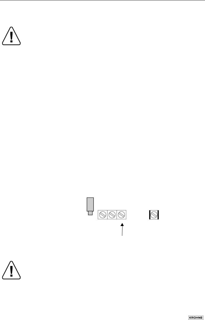
1.1.3 Cable entries |
|
|
|
|
|
NOTE: |
|
|
|
|
Ensure gaskets are fitted correctly and maintain the following max. torques! |
|
||
|
1 |
Max. torques for M 20, |
4 Nm / 2.8 ft × lbf |
3 |
|
|
1/2" NPT or 1/2" PF adapters: |
||
|
2 |
Max. torques for M 20 only: |
3 Nm / 2.1 ft × lbf |
|
|
3 |
Gasket |
1 |
|
|
|
|
2 |
|
A) M 20 cable entries
These cable entries may only be used for flexible electrical cables if the relevant electrical regulations so allow, e.g. National Electric Code (NEC).
Do not fix rigid metal conduits (IMC) or flexible plastic conduits to the M 20 cable entries, refer to “Point B, C” below (1/2” NPT or PF adapters).
B) ½" NPT adapters C) ½" PF adapters
For most North American systems the regulations require that electrical conductors be laid in conduits, particularly for power voltages > 100 V AC.
In such cases, use the 1/2" NPT or 1/2" PF adapters to which flexible plastic conduits can be screwed. Do not use rigid metal conduits (IMC)!
Lay conduits such that no moisture can penetrate into the converter housing.
Should there be risk of any condensation water forming, inside cross-section of the conduit around the cables at these adapters with a suitable sealing compound.
IFC 010 3
1.2 Connection to power
Rated values: The flowmeter housings protecting the electronic equipment from dust and moisture must always be kept closed. The selected creepage distances and clearances have been sized in conformity with VDE 0110 and IEC 664 for contamination category 2. Supply circuits and output circuits are designed to meet the standards of overvoltage classes III and II, respectively.
Safety isolation: the flowmeters (signal converters) must be provided with an isolating facility.
1. AC Version |
2. AC Version |
230/240 V AC (200 - 260 V AC) |
200 V AC (170 - 220 V AC) |
switchable to |
switchable to |
115/120 V AC (100 - 130 V AC) |
100 V AC (85 - 110 V AC) |
Note information on instrument nameplate: supply voltage and frequency
The PE protective ground conductor for the power supply must be connected to the separate U-clamp terminal in the terminal compartment of the signal converter. For exceptions (compact systems), refer to installation instructions for the flow sensor.
Connection diagrams I and II for electrical connection between flow sensor and signal converter: refer to
Section 1.3.5.
3. AC Version |
DC Version |
48 V AC (41 - 53 V AC) |
24 V DC (11-32 V DC) |
switchable to |
|
24 V AC (20 - 26 V AC) |
|
Note information on instrument nameplate: supply voltage and frequency.
For measurement reasons, connect an FE functional ground conductor to the separate U-clamp terminal in the terminal compartment of the signal converter.
If connected to a functional extra-low voltage source (24 V AC / DC, 48 V AC), provide for protective separation (PELV) in conformity with VDE 0100 / VDE 0106 or IEC 364 / IEC 536, or equivalent national regulations.
Connection diagrams I and II for power supply and electrical connection between flow sensor and signal converter: refer to Section 1.3.5.
Connection to power
Power fuse F1 |
Power |
U-clamp terminal |
AC: 100 – 240 V |
L |
N |
PE |
} |
protective conductor |
AC: 24 / 48 V |
1L~ |
0L~ |
FE |
functional ground |
|
DC: 24 V |
L+ |
L– |
FE |
||
|
|
|
for |
|
|
|
|
|
internal |
|
|
|
|
|
use only |
|
|
Warning:
Instrument must be properly grounded to avoid electrical shock.
4 |
IFC 010 |
1.3 Electrical connection of separate flow sensor
(W Versions)
1.3.1 General information on signal cable A and field current cable C
1.3.2 Grounding of flow sensor
Use of the KROHNE shielded signal cable type DS with foil screen and magnetic shield will ensure proper operation of the equipment.
Signal cable to be permanently laid. Connect shields via stranded drain wires.
Underwater and underground installation possible.
Insulating material is flame-retardant to IEC IEC 332.1 / VDE 0742.
Signal cables are low in halogen, unplasticized, and stay flexible at low temperatures.
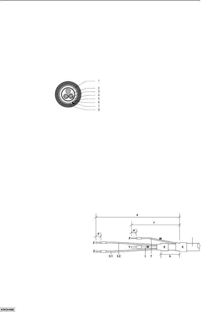
Signal cable Type DS, with double shielding
1Stranded drain wire, 1st shield, 1.5 mm2 or AWG14
2Insulation
3Conductor 0.5 mm2 or AWG 20 (3.1 red / 3.2 white)
4Special foil, 1st shield
5Inner sheath
6Mu-metal foil, 2nd shield
7Stranded drain wire, 2nd shield, 0.5 mm2 or AWG 20
8Outer sheath
Field current cable C with single shielding
Cross-section is dependent on required length of cable, see Table in Sect. 1.3.4.
All flowmeters must be properly grounded.
The grounding conductor should not transmit any interference voltages. Do not ground any other electrical device together with this conductor.
The flow sensor is connected to ground by means of an FE functional ground conductor.
Special information on grounding various flow sensors is contained in the separate installation instructions for flow sensors.
These instructions also contain detailed descriptions on how to use grounding rings and how to install flow sensors in metal or plastic pipes or internally coated pipelines.
1.3.3 Cable preparation |
Customer-supplied materials |
|
|
W |
Insulation tubing (PVC), Ø 2.0-2.5 mm (dia. 1") |
|
X |
Heat-shrinkable tubing or cable sleeve |
|
Y |
Wire end sleeve to DIN 41 228: E 1.5-8 |
|
Z |
Wire end sleeve to DIN 41 228: E 0.5-8 |
Preparation for connection to flow sensor
Length |
Ferrule |
|
|
mm |
inch |
a |
55 |
2.17 |
b |
10 |
0.39 |
c |
15 |
0.59 |
d |
8 |
0.30 |
DS signal cable bending radius ≥ 50 mm (≥ 2")
IFC 010 |
5 |
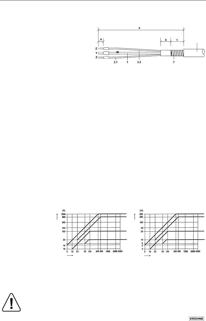
1.3.4 Cable lengths (max. distance between signal converter and flow sensor)
Preparation for connection to IFC 010 W signal converter
Length |
Ferrule |
|
|
mm |
inch |
a |
90 |
3.60 |
b |
8 |
0.30 |
c |
25 |
1.00 |
d |
8 |
0.30 |
DS signal cable bending radius ≥ 50 mm (≥ 2")
External shielding of DS signal cable
Wrap stranded drain wire (7) around the metal foil and clamp under the shield terminal in the signal converter terminal box.
Abbreviations and explanatory notes
used in the following tables, diagrams and connection diagrams
CField current cable C, with single shielding, type and length see Table
DHigh-temperature silicone cable, 3 × 1.5 mm2 (14 AWG) Cu, with single shielding, max. length 5 m (16 ft)
EHigh-temperature silicone cable, 2 × 1.5 mm2 (14 AWG) Cu, max. length 5 m (16 ft)
L Cable length
CB Intermediate connection box required in connection with cables D and E for flow sensors
OPTIFLUX 4000 F, 5000 F and 6000 F in cases where process temperatures exceed 150 °C (302 °F)
Recommended length of signal cable
for magnetic field frequency ≤ 1/6 × power frequency
Flow sensor |
Meter size |
|
|
|
|
Signal cable |
|
|
|
DN mm |
|
|
inch |
|
|
|
|
OPTIFLUX 1000 F |
10 |
– |
15 |
3/8 |
– |
1/2 |
DS A4 |
|
|
25 |
– |
150 |
1 |
– |
6 |
DS A3 |
|
AQUAFLUX F |
10 |
– |
1000 |
3/8 |
– |
40 |
DS A1 |
|
OPTIFLUX 4000 F |
10 |
– |
150 |
3/8 |
– |
6 |
DS A2 |
|
|
200 |
– |
1000 |
8 |
– |
40 |
DS A1 |
|
OPTIFLUX 5000 F |
4.5 |
– |
15 |
1/8 |
– |
1/2 |
DS A4 |
|
|
25 |
– |
100 |
1 |
– |
4 |
DS A2 |
|
OPTIFLUX 6000 F |
10 |
– |
15 |
1/8 |
– |
1/2 |
DS A4 |
|
|
25 |
– |
80 |
1 |
– |
3 |
DS A4 |
|
Cable |
|
|
|
|
|
|
Cable |
|
length |
|
|
|
|
|
DS1 |
length |
DS1 |
|
|
|
|
|
|
DS2 |
|
DS2 |
|
|
|
|
|
|
DS3 |
|
DS3 |
|
|
|
|
|
|
DS4 |
|
DS4 |
Electrical conductivity of process liquid Electrical conductivity of process liquid
Field current cable C: max. length and min. cross-section
Length |
|
|
|
Type of cable, single shielding |
||||
0 |
- 150 m |
5 |
- |
500 ft |
2 × 0.75 mm2 |
Cu |
/ |
2 × 18 AWG |
150 |
- 300 m |
500 |
- |
1000 ft |
2 × 1.50 mm2 |
Cu |
/ |
2 × 14 AWG |
Warning:
Instrument must be properly grounded to avoid electrical shock.
6 |
IFC 010 |
 Loading...