


 Loading...
96M11216
Hand-held
Laser Barcode Reader
BL-N70 Series
User's Manual
Read this manual before using the system in order to achieve maximum performance.
Keep this manual in a safe place after reading it so that it can be used at any time.
Introduction
This manual contains information about procedures for handling, operations, warnings, and precautions about the "Hand-held Laser Barcode Reader BL-N70 Series".
Be sure to read this section thoroughly before use. Keep this manual in a safe place for future reference.
z Symbols
The following symbols and conventions alert you to important messages. Be sure to read these messages carefully.
Failure to follow instructions may lead to physical injury, such as electric shock WARNING or burns.
Failure to follow instructions may lead to product damage.
CAUTION
Note Provides additional information on proper operations.
Reference Provides advanced and useful information for operation.
 Indicates reference pages in this or another manual.
zGeneral Cautions
•Do not modify the BL-N70 series, or use it in any way other than described in the specifications.
•When the BL-N70 series is used in combination with other devices, functions and performance may be degraded, depending on the operating conditions and surrounding environment.
•Do not use the BL-N70 series for the purpose of protecting the human body.
zTrademarks
•Windows Vista/XP/2000/98 are the registered trademarks of Microsoft Corporation, U.S.A.
 Safety Precautions
z Safety Precautions on Laser Apparatus
The "Hand-held Laser Barcode Reader BL-N70 Series" employs a visible red semiconductor laser for its light source. This laser has a wavelength of 650 nm and is classified as a Class 1 laser under IEC60825-1 (Safety of laser products). Do not disassemble or modify the BL-N70 series.
|
|
|
Use of controls or adjustments or performance of procedures other than those |
|
|
|
CAUTION |
specified herein may result in hazardous radiation exposure. Exposure to laser |
|
|
|
|||
|
|
|
light may cause damage to eyes. |
|
|
|
|
|
|
|
|
|
|
|
Item |
|
BL-N70 series |
||
Wavelength |
|
650 nm |
||
Output |
|
40 μW |
||
Pulse width |
|
1.5 ms |
||
Class |
|
Class 1 (IEC 60825-1) |
||
|
|
|
|
|
•Do not look directly into laser light or reflected laser light from a mirrored surface. Otherwise, eye injury may result. Laser light will not cause damage if it strikes exposed skin, but laser light should not deliberately be aimed towards a human body.
•Do not disassemble the BL-N70 series. The BL-N70 series does not automatically stop emitting the laser when the reader is disassembled. Therefore, if someone disassembles the reader, he/she may be exposed to
|
WARNING |
the laser beam and may suffer eye injury. |
•Be sure to stop the laser emission before cleaning the portion of the laser scanner where laser light is generated and received (emitter/receiver). Otherwise, exposure to the laser may cause eye injury.
•Be careful of the path of the laser beam.
Be especially careful of reflected laser light from a mirrored surface.
Do not use the BL-N70 series where the path of the laser beam is at the same height as that of the human eye.
96M11216 |
1 |


 Operating Precautions
z Operations
•Do not use a voltage other than 5V DC with the BL-N70 series. Doing so may lead to breakdown on the unit. When using the dedicated power sources BLU1, BL-U2, or N-42 use a power supply within the appropriate range for each communication unit.
•Be sure to turn the power off to devices attached to the BL-N70 series when you plug or unplug the cables. Failure to do so may cause damage to the BLN70 series.
•Do not disassemble or modify the BL-N70 series. Doing so may lead to breakdown on the unit.
•Keep the cables away from high-tension cables or power sources. Otherwise, noise could cause malfunctions or accidents.
•The BL-N70 series passes the drop impact resistance test, but take care not to expose the unit to excessive shock.
•Do not hold the BL-N70 series by its cable. The unit may become damaged.
z Cleaning
•Do not allow water, oil, dust, or other foreign substance to stick to the laser emitter/receiver. This may cause read errors. When the BL-N70 series becomes dirty or stained, clean the surface using an eyeglass cleaning cloth or a soft cloth that has been dampened with a specialty cleaner for plastics that can handle acrylic.
(Substances such as ethanol can make acrylics cloudy.)
z Operation Environment/Conditions
 CAUTION To use the BL-N70 series correctly and safely, avoid installing it in the following locations. Failure to do so may cause fire, electric shock, damage, accidents, or malfunctions.
•Locations where the BL-N70 series is exposed to direct sunlight
•Locations where the ambient temperature drops below 0°C or exceeds +40°C
•Locations where the ambient humidity goes outside of the range of 35 to 85%RH
•Locations where the temperature changes rapidly, causing condensation
•Locations where there are flammable or corrosive gases
•Locations where there is a large amount of airborne dust, salt, iron, and greasy fumes
•Locations where the ambient lighting exceeds the regulation range
•Locations where the unit may be directly subjected to vibration or impact
•Locations where water, oil or chemicals may splash onto the unit
•Locations where a strong magnetic or electric field is generated.
z Procedures during Malfunction
Turn off the dedicated power source immediately in the following cases. Using the unit in abnormal conditions could cause fire, electric shock, or accidents. Contact your nearest KEYENCE office (listed at the end of the manual) for repair if :
•chemicals, debris, or liquids, including water, enter the BL-N70.
•the BL-N70 is damaged.
•smoke or abnormal odors are emitted from the BL-N70 series.
z For Obtaining the UL Certification
Use the NEC Class 2 output power supply for UL application.
2
Organization of the Manual
1
2
3
4
Getting
Started
Connections
Scanning
Barcodes
Programming
BL-N70
Settings
Appendices
This chapter explains the package contents, the names and functions of each part, and the basic methods for operation.
This chapter describes how to connect various BL-N70 series scanners.
This chapter describes reading data, the format for sending read data, and the connection interfaces.
This chapter describes how to change settings on the BL-N70 series.
This chapter provides specifications, dimensions, settings, and information about replacing the communication cable.
3
1
2
3
4


 Table of Contents
Introduction
Safety Precautions . . . . . . . . . . . . . . . . . . . . . . . . . . . . . . . . . . . . . . . . 1
Operating Precautions . . . . . . . . . . . . . . . . . . . . . . . . . . . . . . . . . . . . . 2
Organization of the Manual . . . . . . . . . . . . . . . . . . . . . . . . . . . . . . . . . . 3
Table of Contents . . . . . . . . . . . . . . . . . . . . . . . . . . . . . . . . . . . . . . . . . 4
Chapter 1 Getting Started
1-1 Package Contents. . . . . . . . . . . . . . . . . . . . . . . . . . . . . . . . . . 1-2
1-2 Identifying Part Names and Functions . . . . . . . . . . . . . . . . . . 1-5
1-3 Using Basic Operations . . . . . . . . . . . . . . . . . . . . . . . . . . . . . 1-6
Reading a barcode . . . . . . . . . . . . . . . . . . . . . . . . . . . . . . . . . 1-6
Chapter 2 Connections
2-1 Connecting the BL-N70VE . . . . . . . . . . . . . . . . . . . . . . . . . . . 2-2
2-2 Connecting the BL-N70UBE . . . . . . . . . . . . . . . . . . . . . . . . . . 2-3
2-3 Connecting the BL-N70RE . . . . . . . . . . . . . . . . . . . . . . . . . . . 2-5
2-4 Connecting the BL-N70RKE . . . . . . . . . . . . . . . . . . . . . . . . . . 2-6
Chapter 3 Scanning Barcodes
3-1 Scanning . . . . . . . . . . . . . . . . . . . . . . . . . . . . . . . . . . . . . . . . . 3-2
3-2 Trigger Modes. . . . . . . . . . . . . . . . . . . . . . . . . . . . . . . . . . . . . 3-4
3-3 Data Send Format. . . . . . . . . . . . . . . . . . . . . . . . . . . . . . . . . . 3-5 Data format . . . . . . . . . . . . . . . . . . . . . . . . . . . . . . . . . . . . . . . 3-5 Inter character delay . . . . . . . . . . . . . . . . . . . . . . . . . . . . . . . . 3-6
3-4 Interface Settings for RS-232C or Keyboard/USB . . . . . . . . . 3-7 Keyboard/USB settings (BL-N70VE/UBE) . . . . . . . . . . . . . . . 3-7 RS-232C settings (BL-N70RE/RKE). . . . . . . . . . . . . . . . . . . . 3-7
4

Chapter 4 Programming BL-N70 Settings
4-1 |
Using Program Mode . . . . . . . . . . . . . . . . . . . . . . . . . . . . . . |
. 4-2 |
|
Setting procedure . . . . . . . . . . . . . . . . . . . . . . . . . . . . . . . . . . |
4-2 |
4-2 |
Starting and Ending Program Mode . . . . . . . . . . . . . . . . . . . . |
4-3 |
|
Start / End Programming Mode . . . . . . . . . . . . . . . . . . . . . . . |
4-3 |
|
Initialize . . . . . . . . . . . . . . . . . . . . . . . . . . . . . . . . . . . . . . . . . . |
4-3 |
4-3 |
Activating / Deactivating Barcode Symbologies . . . . . . . . . . . |
4-4 |
|
Symbology settings. . . . . . . . . . . . . . . . . . . . . . . . . . . . . . . . . |
4-4 |
|
UPC/EAN detailed settings . . . . . . . . . . . . . . . . . . . . . . . . . . . |
4-6 |
|
CODE128 detailed settings . . . . . . . . . . . . . . . . . . . . . . . . . . |
4-8 |
|
CODE39 detailed settings . . . . . . . . . . . . . . . . . . . . . . . . . . . |
4-9 |
|
CODABAR detailed settings . . . . . . . . . . . . . . . . . . . . . . . . . |
4-10 |
|
ITF detailed settings . . . . . . . . . . . . . . . . . . . . . . . . . . . . . . . |
4-11 |
|
GS1 Databar Omnidirectional detailed settings . . . . . . . . . . |
4-11 |
|
GS1 Databar Limited detailed settings . . . . . . . . . . . . . . . . . |
4-12 |
|
GS1 Databar Expanded detailed settings. . . . . . . . . . . . . . . |
4-12 |
4-4 |
Trigger Mode Settings . . . . . . . . . . . . . . . . . . . . . . . . . . . . . |
4-13 |
4-5 |
Buzzer Settings. . . . . . . . . . . . . . . . . . . . . . . . . . . . . . . . . . . |
4-14 |
|
Tone selection . . . . . . . . . . . . . . . . . . . . . . . . . . . . . . . . . . . |
4-14 |
|
Buzzer timing . . . . . . . . . . . . . . . . . . . . . . . . . . . . . . . . . . . . |
4-14 |
4-6 |
Decode Settings . . . . . . . . . . . . . . . . . . . . . . . . . . . . . . . . . . |
4-15 |
|
Decode Match Count settings. . . . . . . . . . . . . . . . . . . . . . . . |
4-15 |
|
Duplicate Read Prevention settings . . . . . . . . . . . . . . . . . . . |
4-16 |
4-7 |
Digit Limit Function Settings . . . . . . . . . . . . . . . . . . . . . . . . . |
4-17 |
4-8 Communication Data Format Settings . . . . . . . . . . . . . . . . . |
4-20 |
|
|
Data format . . . . . . . . . . . . . . . . . . . . . . . . . . . . . . . . . . . . . . |
4-20 |
|
Inter character delay settings . . . . . . . . . . . . . . . . . . . . . . . . |
4-21 |
4-9 |
Communication Interface Settings . . . . . . . . . . . . . . . . . . . . |
4-22 |
|
Keyboard/USB settings. . . . . . . . . . . . . . . . . . . . . . . . . . . . . |
4-22 |
|
RS-232C settings . . . . . . . . . . . . . . . . . . . . . . . . . . . . . . . . . |
4-22 |
4-10 |
Decimal Program Code . . . . . . . . . . . . . . . . . . . . . . . . . . . . |
4-24 |
4-11 |
Symbology List . . . . . . . . . . . . . . . . . . . . . . . . . . . . . . . . . . . |
4-25 |
5

Appendices
A-1 Specifications . . . . . . . . . . . . . . . . . . . . . . . . . . . . . . . . . . . . . A-2
A-2 Dimensions . . . . . . . . . . . . . . . . . . . . . . . . . . . . . . . . . . . . . . . A-4
A-3 ASCII Code Table . . . . . . . . . . . . . . . . . . . . . . . . . . . . . . . . . . A-6
A-4 Settings and the Factory Default Values. . . . . . . . . . . . . . . . . A-7 Barcode symbology settings . . . . . . . . . . . . . . . . . . . . . . . . . . A-7 Operation settings. . . . . . . . . . . . . . . . . . . . . . . . . . . . . . . . . A-10 Communication data format . . . . . . . . . . . . . . . . . . . . . . . . . A-12 Communication interface settings. . . . . . . . . . . . . . . . . . . . . A-13
A-5 Replacing the Communication Cable . . . . . . . . . . . . . . . . . . A-14
6

1
Getting Started
This chapter explains the package contents, the names and functions of each part, and the basic methods for operation.
1-1 Package Contents . . . . . . . . . . . . . . . . . . . . . . . 1-2
1-2 Identifying Part Names and Functions . . . . . . 1-5
1-3 Using Basic Operations . . . . . . . . . . . . . . . . . . 1-6
1
Started Getting
1-1

1
Started Getting
1-1  Package Content
The BL-N70 series comes with the following items. Check that all of the items are included.
Hand-held Laser Barcode Reader BL-N70 Series
z BL-N70 unit
Model |
Communication interface |
BL-N70VE |
Keyboard interface |
|
|
BL-N70UBE |
USB interface |
|
|
BL-N70RE |
RS-232C interface |
|
|
BL-N70RKE |
Keyence RS-232C interface |
|
|
BL-N70VE |
BL-N70UBE |
BL-N70RE |
BL-N70RKE |
z AC adapter |
z User's Guide |
(BL-N70RE only) |
|
Read achieve canKeep this
|
Laser |
|
|
||
|
Hand-held |
Barcode |
|
||
BL- |
Reader |
||||
|
|||||
User’s |
N70 |
Series |
|||
this manual |
|
Manual |
|
||
mmaximum |
before using |
|
|
||
to
it
1-2
1-1 Package Contents
Optional
zStand
OP-77470: Use this stand when placing the BL-N70 series on a table top.
1
Started Getting
z Replacement cables
OP-77466: For BL-N70VE |
OP-77467: For BL-N70UBE |
OP-77468: BL-N70RE |
OP-77469: For BL-N70RKE |
Reference |
For the procedure to replace the cable, see |
|
"A-5 Replacing the Communication |
|
|||
Cable" on page A-14. |
|
|
|
|
|
|
|
|
|
|
|
1-3
1
Started Getting
1-1 Package Contents
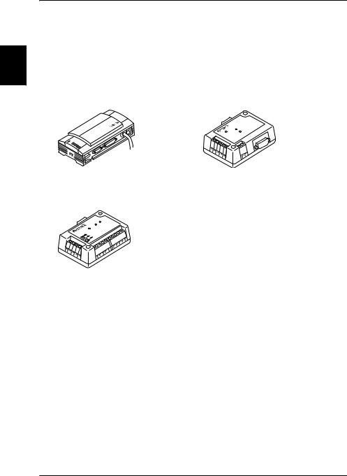
z Communication unit (for BL-N70RKE only)
Model |
Power supply |
Communication interface |
BL-U1 |
100 to 240 V AC |
Select RS-232C or RS-422A |
|
|
|
BL-U2 |
24 V DC |
RS-232C |
|
|
|
N-42 |
24 V DC |
RS-422A |
|
|
|
BL-U1 |
|
BL-U2 |
N-42
1-4
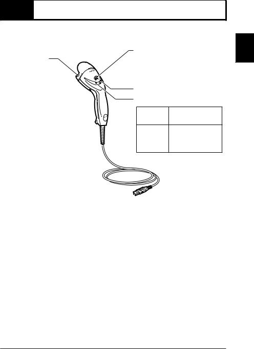
1-2  Identifying Part Names and Functions
This chapter describes names and jobs of each part of the BL-N70 series.
Emitter/receiver:
Emits and receives laser light.
Trigger switch:
Use the switch to read a barcode.
Red LED for operation status |
Green LED for operation status
LED color |
LED lighting |
Red |
When laser emits |
When the power is
Green
turned on
While reading the barcode
1
Started Getting
Connector: 
Use the connector to connect to a computer or to a reader port with a dedicated power source.
The shape of the connector is different for each model.
1-5

1
Started Getting
1-3  Using Basic Operations
This section explains basic methods for operating the barcode reader.
Reading a barcode
Point the laser emitter/receiver towards the barcode and press the trigger switch about 100 mm (4") from the barcode.
•The green status LED lights up when the barcode has been read correctly. A buzzer sounds after the reading is complete or after read data is sent.
(The buzzer can be disabled. see  page 4-14)
• Barcode data is sent to the connected computer or other device.
z Precautions for reading
Adjust the scan line so it completely covers the barcode from end to end.
Correct scan method
Incorrect scan method
You cannot specify which barcode to read.
1-6

2
Connections
This chapter describes how to connect various BL-N70 series scanners.
2-1 Connecting the BL-N70VE . . . . . . . . . . . . . . . . 2-2
2-2 Connecting the BL-N70UBE . . . . . . . . . . . . . . . 2-3
2-3 Connecting the BL-N70RE . . . . . . . . . . . . . . . . 2-5
2-4 Connecting the BL-N70RKE . . . . . . . . . . . . . . . 2-6
2
Connections
2-1
2
Connections
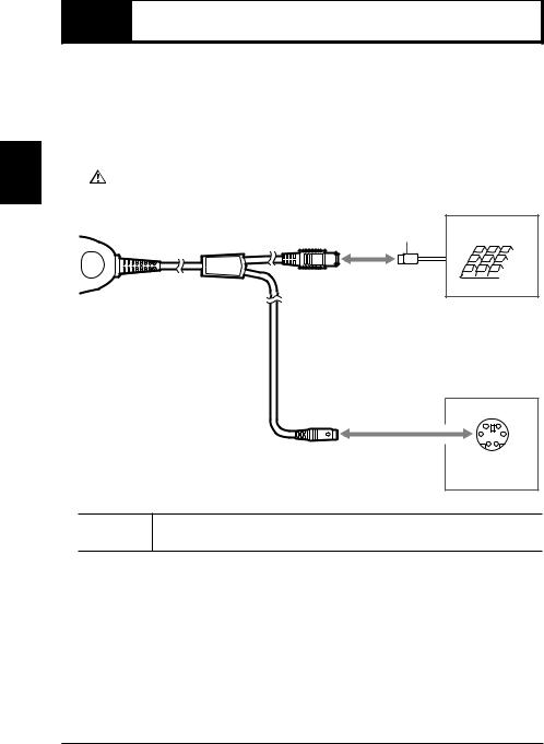
2-1  Connecting the BL-N70V
Turn off main power to the PC before proceeding.
Power for the BL-N70VE will be supplied through the computer's keyboard receptacle. (BL-N70VE is compatible with PC's running Windows Vista, XP, 2000 or 98)
Connect the 6 pin Mini DIN plug (A) to the computer's Keyboard receptacle. Connect the 6-pin Mini DIN receptacle (B) to the plug from a Keyboard (if desired).
|
|
CAUTION |
Do not remove the cables while the computer is turned on as this may cause |
|
|
||
|
|
the computer or BL-N70VE to malfunction. |
|
|
|
|
|
|
|
|
|
|
|
|
|
BL-N70VE |
|
To keyboard |
|
(B) |
PS/2 connector |
|
|
To computer
(A)
PS/2 connector (Mini DIN 6-pin)
Reference
When connecting a keyboard connector plug to an AT connector, use a commercial AT to PS/2 keyboard conversion adapter for the connection.
zPrecautions when using the computer
•DO NOT USE THE KEYBOARD WHEN SCANNING BARCODES ! Typing while scanning barcodes will corrupt the data string.
•If the computer has multiple language settings, make sure that the input mode is set for half-width alphanumeric characters.
• The keyboard specifications can be selected ( page 3-7).
2-2
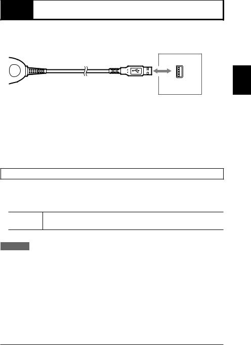
2-2  Connecting the BL-N70UBE
The BL-N70UBE connects to a PC's USB port, power is supplied through the USB port. (BL-N70UBE is compatible with PC's running Windows Vista, XP, 2000 or 98)
BL-N70UBE
To computer
USB port (A type)
zPrecautions when using the computer
•DO NOT USE THE KEYBOARD WHEN SCANNING BARCODES ! Typing while scanning barcodes will corrupt the data string.
•If the computer has multiple language settings, make sure that the input mode is set for half-width alphanumeric characters.
• The keyboard specifications can be selected ( page 3-7).
Installing the USB Driver
When BL-N70UBE is first connected to a computer running Windows 98, the USB driver installation screen appears. Install the driver by following the directions given on the screen. (This procedure is not necessary when using a computer running Windows Vista/XP/2000).
Note
Connect the barcode reader after turning on the computer to ensure that it is properly detected.
Procedure
1 The "Add New Hardware Wizard" dialog appears and the message "This window searches for new drivers for: USB human interface device" is displayed. Click on the [Next] button.
2 The message "What do you want Windows to do?" is displayed. Select [Search for the best driver for your device (Recommended).] and click on the [Next] button.
2
Connections
2-3

2
Connections
2-2 Connecting the BL-N70UBE
3 Click on the [Next] button. "USB human interface device" is displayed and the message "Windows driver search for the device:" appears. Click on the [Next] button.
Note The CD-ROM (Windows) may be required at this point.
4 Windows begins installing the driver. When installation is complete, the message "Windows has finished installing the software that your new hardware device requires." appears. Click on the [Finish] button.
2-4
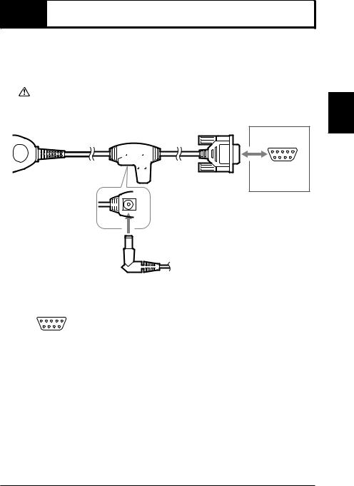
2-3  Connecting the BL-N70RE
The BL-N70RE directly connects to the serial port (RS-232C D-sub 9-pin connector) of a DOS/V computer.
Supply power by using the included AC adapter.
|
|
|
• Be sure to use the AC adapter provided with the device. Connecting to other |
|
|
CAUTION |
power sources may cause damage. |
|
|
||
|
|
• Supply the AC adapter with a power source of AC 120 V ±10%. Using other |
|
|
|
|
|
|
|
|
power sources may cause damage. |
|
|
|
|
|
|
|
|
BL-N70RE
To computer
DOS/V computer (D-sub 9-pin)
AC adapter
Connector pins for BL-N70RE
5 4 3 2 1 |
|
Pin No. |
Symbol |
Description |
Signal direction |
|
|
2 |
SD (TXD) |
Sends data |
Output |
||
|
|
|
|
|
|
|
|
|
3 |
RD (RXD) |
Receives data |
Input |
|
9 8 7 6 |
|
4 |
- |
N/C |
- |
|
D-sub 9-pin (female) |
|
5 |
SG |
Signal ground |
- |
|
|
|
|
|
|
||
6 |
- |
N/C |
- |
|||
#4-40 screws |
|
|||||
|
|
7 |
CS (CTS) |
Ready to send data |
Input |
|
|
|
|
|
|
|
|
|
|
8 |
RS (RTS) |
Request to send data |
Output |
|
|
|
|
|
|
|
z Communication Settings
The following values represent factory settings for the BL-N70RE. The settings can be changed ( page 4-22). Make sure that the settings for BL-N70RE and the connected computer are the same.
• Baud rate |
: 9600 bit/s |
• Data length |
: 7 bits |
• Parity |
: Even |
• Stop bit |
: 1 bits |
• Communication protocol : No protocol
2
Connections
2-5

2
Connections
2-4  Connecting the BL-N70RKE
BL-N70RKE can be connected to the AutoID data controller DV-90 and to the dedicated communication units BL-U1, BL-U2, and N-42. These components have a regulated 5VDC power supply on Pin 9 of the D-sub connector.
BL-N70RKE |
To Keyence |
|
|
|
products |
|
(D-sub 9-pin) |
Connector pins for BL-N70RKE |
|
|
|
5 4 3 2 1 |
|
|
|
Pin No. |
Symbol |
Description |
Signal direction |
|
|
|
|
|
|
2 |
RD (RXD) |
Receives data |
Input |
||
|
|
|
|
|
|
|
3 |
SD (TXD) |
Sends data |
Output |
|
|
9 8 7 6 |
|
|
|
4 |
- |
Does not make any connection |
- |
|
|
|
D-sub 9-pin (female) |
|
|
5 |
SG |
Signal ground |
- |
||
|
|
|
|
6 |
- |
Does not make any connection |
- |
|||
|
|
|
#4-40 screws |
|
|
|||||
|
|
|
|
|
|
|
7 |
RS (RTS) |
Request to send data |
Output |
|
|
|
|
|
|
|
|
|
|
|
|
|
|
|
|
|
|
8 |
CS (CTS) |
Ready to send data |
Input |
|
|
|
|
|
|
|
9 |
Vcc |
Inputs +5V DC power supply |
Input |
|
|
|
|
|
|
|
|
|
|
|
|
|
|
|
|
Although it may be possible to connect the BL-N70RKE to external power |
|||||
|
|
|
CAUTION |
|
supplies, it is not recommended. Applying more than 5VDC +/-5% may |
|||||
|
|
|
|
|||||||
|
|
|
|
|
damage the scanner. |
|
|
|||
|
|
|
|
|
|
|
|
|
|
|
|
|
|
|
|
|
|
|
|
|
|
z Communication Settings
The following values represent factory settings for the BL-N70RKE. The settings can be changed ( page 4-22). Make sure that the settings for BL-N70RKE and the connected
equipment are the same. |
|
• Baud rate |
: 9600 bit/s |
• Data length |
: 7 bits |
• Parity |
: Even |
• Stop bit |
: 1 bits |
• Communication protocol : No protocol
2-6
3
Scanning Barcodes
This chapter describes reading data, the format for sending read data, and the connection interfaces.
3-1 Scanning . . . . . . . . . . . . . . . . . . . . . . . . . . . . . . 3-2 3-2 Trigger Modes . . . . . . . . . . . . . . . . . . . . . . . . . . 3-4 3-3 Data Send Format . . . . . . . . . . . . . . . . . . . . . . . 3-5 3-4 Interface Settings for RS-232C or Keyboard/USB. . . 3-7
3
Barcodes Scanning
3-1

3
Barcodes Scanning
3-1  Scanning
The laser turns on when the trigger switch on the BL-N70 is pressed. While holding the trigger switch, bring the BL-N70 scanner towards the barcode to a distance that complies with the reading range characteristics on  page A-3. Ensure that the entire code fits within the scan line.
•Only shine the laser light on one barcode at a time. To enter two or more barcodes, read each barcode separately one after the other.
Note
•Do not shine the laser light on the barcode label at an angle. The reader may not be able to read the barcode.
z Trigger modes
There are three modes that can be used when pressing the trigger switch. Choose the most appropriate mode for the situation ( page 3-4).
•Trigger switch mode – Laser OFF until trigger is depressed. Barcodes scanned only while trigger is depressed
•Continuous emission mode – Laser always ON. Barcodes scanned only while trigger is depressed
•Continuous reading mode – Laser always ON. Barcodes always scanned. No trigger required.
z Data Send Format
Read data is sent to the connected computer or other device.
• For the format of the sent data, see  page 3-5.
•For information about the communication protocols when using BL-N70RE/RKE, see
 page 3-7.
3-2
Loading...