


KAC-X650D KAC-PS650D
5-CHANNEL POWER AMPLIFIER 7page 2-15
INSTRUCTION MANUAL
AMPLIFICATEUR DE PUISSANCE 5 CANAUX 7page 16-29
MODE D’EMPLOI
AMPLIFICADOR DE POTENCIA DE 5 CANALES 7página 30-43
MANUAL DE INSTRUCCIONES
Take the time to read through this instruction manual. Familiarity with installation and operation procedures will help you obtain the best performance from your new power amplifier.
For your records
Record the serial number, found on the back of the unit, in the spaces designated on the warranty card, and in the space provided below. Refer to the model and serial numbers whenever you call upon your KENWOOD dealer for information or service on the product.
Model KAC-X650D/PS650D Serial number
© PRINTED IN JAPAN B64-2270-00 (KM / EM)
Safety precautions
2WARNING
To prevent injury or fire, take the following precautions:
•When extending the ignition, battery, or ground wires, make sure to use automotivegrade wires or other wires with a 8mm2 (AWG8) or more to prevent wire deterioration and damage to the wire coating.
•To prevent a short circuit, never put or leave any metallic objects (such as coins or metal tools) inside the unit.
•If the unit starts to emit smoke or strange smells, turn off the power immediately and consult your Kenwood dealer.
•Do not touch the unit during use because the surface of the unit becomes hot and may cause burns if touched.
2CAUTION
To prevent damage to the machine, take the following precautions:
•Be sure the unit is connected to a 12V DC power supply with a negative ground connection.
•Do not open the top or bottom covers of the unit.
•Do not install the unit in a spot exposed to direct sunlight or excessive heat or humidity. Also avoid places with too much dust or the possibility of water splashing.
•When replacing a fuse, only use a new one with the prescribed rating. Using a fuse with the wrong rating may cause your unit to malfunction.
•To prevent a short circuit when replacing a fuse, first disconnect the wiring harness.
NOTE
•If you experience problems during installation, consult your Kenwood dealer.
•If the unit does not seem to be working right, consult your Kenwood dealer.
FCC WARNING
This equipment may generate or use radio frequency energy. Changes or modifications to this equipment may cause harmful interference unless the modifications are expressly approved in the instruction manual. The user could lose the authority to operate this equipment if an unauthorized change or modification is made.
NOTE
This Class B digital apparatus complies with Canadian ICES-003.
Cleaning the unit
If the front panel gets dirty, turn off the power and wipe the panel with a dry silicon cloth or soft cloth.
2CAUTION
Do not wipe the panel with a hard cloth or a cloth dampened by volatile solvents such as paint thinner and alcohol. They can scratch the surface of the panel and/or cause the indicator letters to peel off.
To prevent batter rise
When the unit is used in the ACC ON position without turning the engine ON, it depletes the battery. Use it after starting the engine.
Protection function
There is a Protection function installed in the unit to protect the unit and speakers from various problems. When Protection operates, the indicator informs you of the condition. (Refer to page 6)
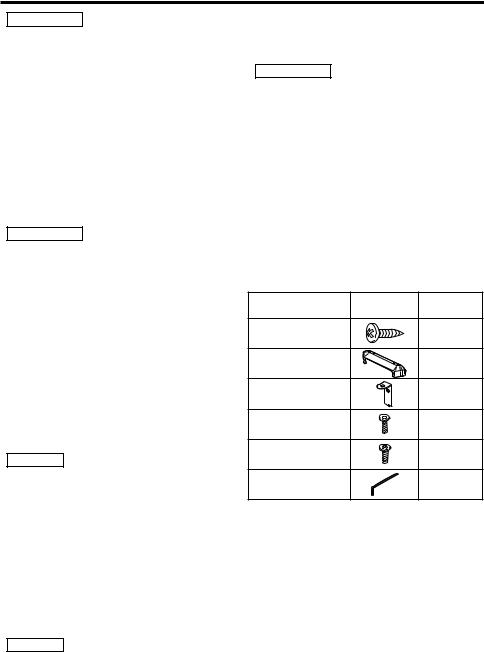
Accessories
Part name |
External |
Number of |
|
View |
Items |
||
|
|||
Self-tapping screws |
|
4 |
|
(ø5 × 18 mm) |
|
||
|
|
||
Terminal cover |
|
2 |
|
Mounting Hardware |
|
4 |
|
Hexagon socket head |
|
4 |
|
cap screw (M3 × 8 mm) |
|
||
|
|
||
Self-tapping screws |
|
4 |
|
(ø3 × 8 mm) |
|
||
|
|
||
Hexagon Wrench |
|
1 |
2 English
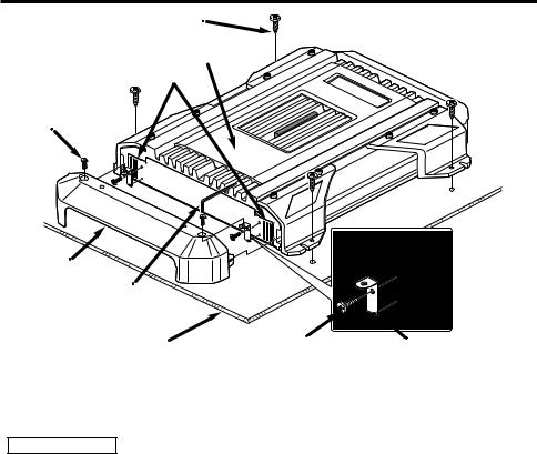
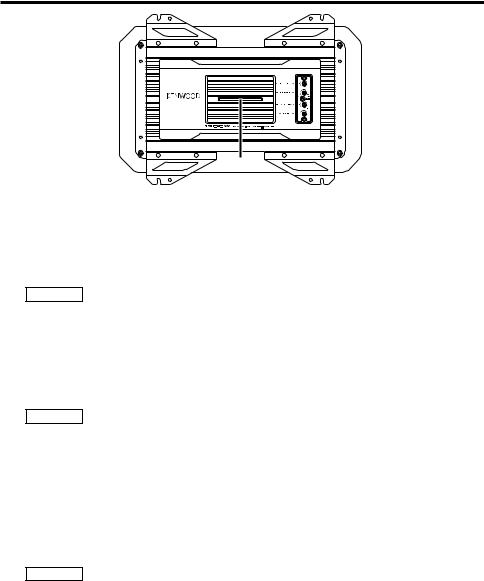
Installation
Self-tapping screw (ø5 × 18 mm)
Hexagon socket head cap screw (M3 × 8 mm)
Cooling fan : Air inlet
Exhaust outlet |
Terminal cover
Hexagon
Wrench
Installation board, etc.  (thickness : 15 mm or more)
1.Install the installation fittings in the unit.
2.Attach the unit.
3.Install the terminal cover.
2CAUTION
Self-tapping screws |
Mounting |
(ø3 × 8 mm) |
Hardware |
•Do not install in the below locations;
(Unstable location, In a location that interferes with driving, In a location that gets wet, In a dusty location, In a place that gets hot, In a place that gets direct sunlight, In a location that gets hit by hot air)
•Do not install the unit under the carpet. Otherwise heat build-up occurs and the unit may be damaged.
•Install this unit in a location which allows heat to easily dissipate. Once installed, do not place any object on top of the unit.
•The surface temperature of the amplifier will become hot during use. Install the amplifier in a place where people, resins, and other substances that are sensitive to heat will not come into contact with it.
•This unit has cooling fans to decrease the internal temperature. Be careful not to block the cooling fan openings when installing the unit. Blocking these openings will inhibit the cooling of the internal temperature and result in malfunction.
•When making a hole under a seat, inside the trunk, or somewhere else in the vehicle, check that there is nothing hazardous on the opposite side such as a gasoline tank, brake pipe, or wiring harness, and be careful not to cause scratches or other damage.
•Do not install near the dashboard, rear tray, or air bag safety parts.
•The installation to the vehicle should securely fasten the unit to a place in which it will not obstruct driving. If the unit comes off due to a shock and hits a person or safety part, it may cause injury or an accident.
•After installing the unit, check to make sure that electrical equipment such as the brake lamps, turn signal lamps and windshield wipers operate normally.
English 3
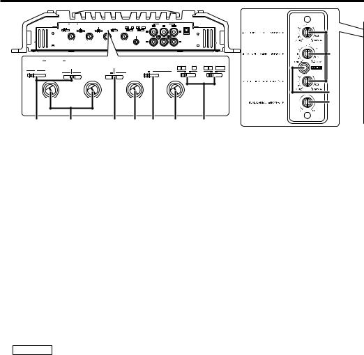
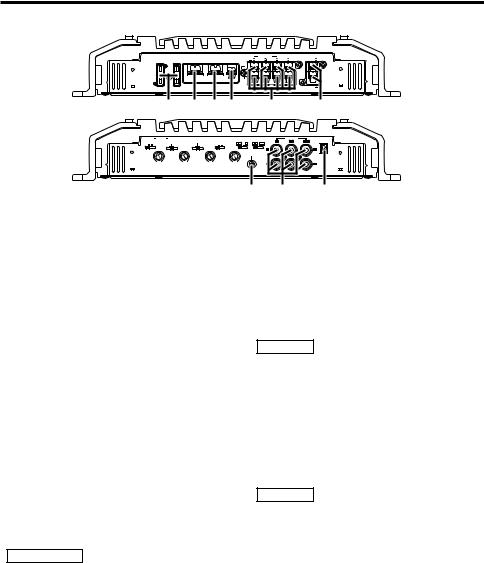
Controls
|
A.CH |
FILTER B.CH |
B.M.S. |
OPERATION |
|
INPUT SELECTOR |
|
LINE IN |
EXT.AMP.CONT. |
|
|
|
OFF HPF |
OFF |
OFF |
STEREO MONO(Lch) |
A B A A B SUB |
A |
B |
SUB |
|
|
|
|
HPF LPF |
REMOTE +12dB |
|
|
|
|
|
||||
A.CH FILTER |
B.CH |
|
B.M.S. |
|
OPERATION |
INPUT SELECTOR |
|||||
OFF HPF |
OFF |
|
OFF |
|
STEREO |
MONO(Lch) |
A B |
A |
A B SUB |
||
|
HPF |
LPF |
REMOTE +12dB |
|
|
|
|
|
|
||
50 |
200 |
50 |
200 |
50 |
200 |
50 |
200 |
A.CH HPF |
B.CH HPF |
B.CH LPF |
SUB.CH LPF |
||||
|
|
|
FILTER FREQUENCY(Hz) |
|
|
|
|
1 |
2 |
|
3 |
4 |
5 |
6 |
7 |
8 |
9 |
0 |
The unit is a 5-channel amplifier incorporating 2 stereo amplifiers and 1 monaural amplifier in a single body.
The stereo amplifier on one side is called amplifier A, while the one on the other side is amplifier B. The monaural amplifier is called the amplifier SUB.
This unit is compatible with a large variety of systems by combining the switches and functions described in the following.
About D-class (SUB.CH)
A D-class amplifier uses an inaudible frequency as a switching pulse to change the pulse width to represent the music signal. (Pulse Width Modulation: P.W.M.)
8INPUT SENSITIVITY control (A.CH/B.CH/SUB.CH)
Adjust this control according to the pre-out level of the center unit connected to this amplifier.
The sensitivities of amplifiers A, B and SUB can be adjusted independently regardless of the position of the input selector switch.
NOTE
Refer to "Specifications" on the center unit’s instruction manual about the pre-out level.
5OPERATION switch
This switch is used to select the operation mode of the amplifier.
This setting is valid for both the amplifier A and B.
•STEREO position:
The amplifier can be used as a stereo amplifier.
•MONO (Lch) position:
Amplifies the signal input from the left side only. Set to this position and make bridged connections to use as a high-power
monaural amplifier. (The input right signal is not output.)
1FILTER switch (A.CH/B.CH)
This switch allows to apply high-pass or low-pass filtering to the speaker outputs.
•HPF (High-Pass Filter) position:
The filter outputs the band of higher frequencies than the frequency set with the HPF FREQUENCY control.
•OFF position:
The entire bandwidth is output without filtering.
•LPF (Low-Pass Filter) position: (B.CH only)
The filter outputs the band of lower frequencies than the frequency set with the LPF FREQUENCY control.
The speaker output is automatically turned monaural (L+R) and the bass boost function is activated.
2HPF FREQUENCY control (A.CH/B.CH)
Sets the cutoff frequency when the FILTER switch is set to HPF.
4B.CH LPF FREQUENCY control
Sets the cutoff frequency when the FILTER switch is set to LPF.
6SUB.CH LPF FREQUENCY control
This control adjusts the frequency band output from this amplifier SUB.
7INPUT SELECTER switch (AB/A)
This switch toggles the input signal of amplifier B.
•AB position:
The input for terminal A is output from amplifier A, while the input for terminal B is output from amplifier B.
4 English
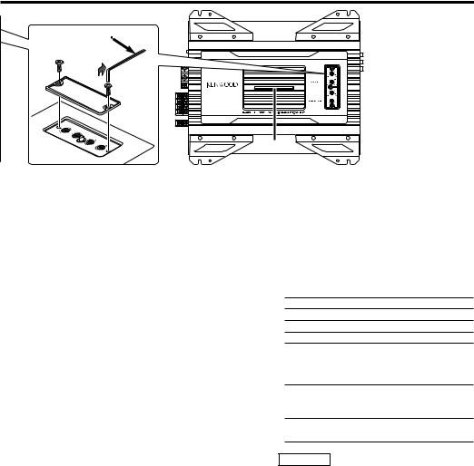
Removing the cover
Hexagon Wrench
Tighten

 Loosen
! |
•A position:
The input for terminal A is output from amplifiers A and B.
(AB/SUB)
This switch toggles the input signal of amplifier SUB.
• AB position:
The input for terminals A and B input is mixed and output from amplifier SUB.
•SUB position:
The input for the SUB terminal is output by amplifier SUB.
3B.M.S.(Bass management system) switch
Bass boost centered on the frequency set by the B.M.S. FREQUENCY control.
The B.M.S. only applies to the amplifier SUB.
•+12 position:
Bass boost +12 dB
•OFF position:
Bass boost OFF
•REMOTE position:
Controls the B.M.S. from the Kenwood center unit. (Refer to page 5)
0 B.M.S. FREQUENCY control
When the B.M.S. switch is set on "+12dB"/ "REMOTE" the emphasized center frequency is adjusted.
9V-COLOR (Variable color) button
Select the ON color for the indicator. Every time the button is pressed, 7 fixed colors and the variable color change.
The color can’t be set when the indicator is blinking.
■Controlling the B.M.S. from the Kenwood center unit
(B.M.S. : Bass management system)
When the B.M.S. switch is set in the remote position, the bass boost amount and frequency offset can be controlled from the center unit.
• Bass boost
Center unit |
Setting |
|
display |
|
|
|
|
|
"Flat"/"OFF"/ "1" |
Bass boost OFF (Flat) |
|
"+6"/ |
"1"/ "2" |
Bass boost +6 dB |
"+12"/ |
"2"/ "3" |
Bass boost +12 dB |
"+18"/ |
"3"/ "4" |
Bass boost +18 dB |
• Frequency offset
Center unit |
Setting |
|
display |
||
|
||
"Normal" |
It is the B.M.S. |
|
|
FREQUENCY control |
|
|
adjustment value. |
|
"Low" |
The central frequency is 20- |
|
|
30% low. |
NOTE
For the center unit control method and setting display, refer to the Instruction Manual for the center unit.
There may be cases when the center unit can’t set the "Bass boost +18dB" or "Frequency Offset".
English 5
Indicator
! |
■Indicator !
You are notified of the unit’s condition and malfunction (Protection function) by the indicator.
•ON or color change in order.
When operation is normal
NOTE
The color you want can be selected with the variable color button.
•The color blinks blue
–When during operation
–When the center unit/B.M.S. switch controls the B.M.S.
•The color blinks yellow
When the power voltage is less than 11V.
NOTE
The cause may be one of the below times.
–When the vehicle battery is weak.
–When the battery capacity is low.
–When the battery cord is worn.
–When the battery wire is too small or too long and can’t supply enough current.
•The color blinks purple
When the unit has failed and direct current voltage is generated to the speaker’s output.
NOTE
Turn the power OFF and release the protection. If the indicator doesn’t quit blinking, contact your Kenwood dealer.
•The color blinks red
When the inside of the unit is overheating.
•The color blinks green
–When the speaker cord is shorted.
–When the speaker output is in contact with the vehicle ground.
6 English
Connection
■ Terminal names
FUSE(30Ax2)
30 |
30 |
|
@ |
|
POWER IN |
SPEAKER |
BRIDGED |
|
|
BATT. |
GND |
P.CON OUTPUT |
LEFT |
RIGHT |
SUB |
|
|
A |
|
|
|
|
|
B |
|
|
|
|
|
|
|
|
SUB |
# $ % |
^ |
|
& |
||
A.CH |
FILTER B.CH |
|
B.M.S. |
|
OPERATION |
INPUT SELECTOR |
|
LINE IN |
EXT.AMP.CONT. |
|||
OFF HPF |
OFF |
|
OFF |
|
STEREO |
MONO(Lch) |
A B |
A |
A B SUB |
A |
B |
SUB |
HPF LPF |
|
REMOTE +12dB |
|
|
|
|||||||
|
|
|
|
|
|
|
|
|
L |
|
|
L |
|
|
|
|
|
|
|
|
GND |
|
|
|
|
50 |
200 |
50 |
200 |
50 |
200 |
50 |
200 |
|
R |
|
|
R |
A.CH HPF |
B.CH HPF |
B.CH LPF |
SUB.CH LPF |
|
|
|
||||||
|
|
|
FILTER FREQUENCY(Hz) |
|
|
|
|
|
|
|
||
* ( )
@ Fuse (30 A × 2)
# Battery terminal $ Ground terminal
^Amplifier A/B speaker output terminals
•Stereo Connections:
When you wish to use the unit as a stereo amplifier, stereo connections are used.
The speakers to be connected should have an impedance of 2Ω or greater. When multiple speakers are to be
connected, ensure that the combined impedance is 2Ω or greater for each channel.
•Bridged Connections:
When you wish to use the unit as a highoutput monaural amplifier, bridged connections are used. (Make connections to the LEFT channel 9 and the RIGHT channel · SPEAKER OUTPUT terminals.)
The speakers to be connected should have an impedance of 4Ω or greater. When multiple speakers are to be
connected, ensure that the combined impedance is 4Ω or greater.
2CAUTION
*RCA cable ground lead terminal
When using an RCA cable with a ground lead attached, connect the ground lead to this terminal.
(A.CH/B.CH/SUB.CH LINE IN terminal
%Power control terminal
Controls the unit ON/OFF.
NOTE
Controls the unit power. Be sure to connect it with all the systems.
)EXT.AMP.CONT. (external amplifier control) terminal
Controls the B.M.S. Only Kenwood center unit models sold in 1999 or later with a "EXT.CONT."/"EXT.AMP.CONT." wire attached can be used.
Also, a maximum of 3 power amplifiers can be operated at the same time.
NOTE
There are cases when operation may not be possible due to wiring wire type and length.
The rated input of the speakers should be no less than the maximum output of the amplifier. Otherwise malfunction may result.
&Amplifier SUB speaker output terminal
As this unit accepts speakers with a minimum impedance of 2 ohms, connect speakers with 2-ohm or higher impedance to these terminals.
English 7

Connection
■ Installation procedure
Since there are large variety of settings and connections possible according to applications, read the instruction manual well to select the proper setting and connection.
1.Remove the ignition key and disconnect the negative - terminal of the battery to prevent short circuits.
2.Set the unit according to the intended usage.
3.Connect the input and output wires of the units.
4.Connect the speaker wires.
5.Connect the power wire, power control wire and grounding wire following this order.
6.Install the unit in the car.
7.Connect the negative - terminal of the battery.
2CAUTION
•If sound is not output normally, immediately turn power off and check connections.
•Be sure to turn the power off before changing the setting of any switch.
•If the fuse blows, check wires for shorts, then replace the fuse with one of the same rating.
•Check that no unconnected wires or connectors are touching the car body. Do not remove caps from unconnected wires or connectors to prevent short circuits.
•Connect the speaker wires to appropriate speaker connectors separately. Sharing the negative wire of the speaker or grounding speaker wires to the metal body of the car can cause this unit to fail.
•After installation, check that the brake lamps, winkers, and wipers work properly.
8 English
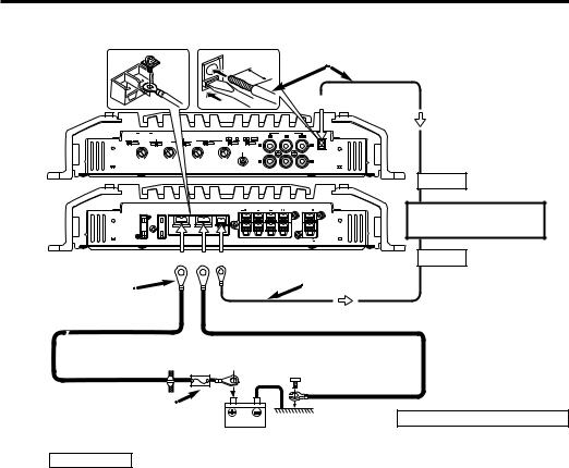
■ Power wire connection
11 mm
The connecting wire diameter*
•If solid wire: Ø0.4 (AWG 26) – Ø1.2 (AWG 16)
•If multi strand wire: Ø0.4 (AWG 26) – Ø1.2 (AWG 16)
)
.
|
|
|
|
L |
L |
|
|
|
|
GND |
|
50 |
200 |
50 |
200 |
R |
R |
.CH LPF |
SUB.CH LPF |
||||
External amplifier control wire (Pink / Black) (Refer to page 7)
EXT.CONT.
POWER IN
GND
30 |
30 |
SPEAKER |
BRIDGED |
|
|
P.CON OUTPUT |
LEFT |
RIGHT |
SUB |
A |
|
|
|
B |
|
|
|
|
|
|
SUB |
CENTER UNIT
(CD receiver, etc.)
|
# $ % |
P.CONT. |
Lead terminal* |
Extension wire* |
Power control wire |
|
||
|
(Blue/ White) |
|
|
|
|
Battery wire* |
Ground wire* |
|
|
|
Protective Fuse*
* : Commercially available parts
Battery
2WARNING
To prevent fire caused by a short in the wiring, connect a fusible link or breaker nearby the battery’s positive terminal.
Wiring
•Take the battery wire for this unit directly from the battery. If it's connected to the vehicle’s wiring harness, it can cause blown fuses etc.
•If a buzzing noise is heard from the speakers when the engine is running, connect a line noise filter (optional) to each of the battery wire.
•Do not allow the wire to directly contact the edge of the iron plate by using Grommets.
•Connect the ground wire to a metal part of the car chassis that acts as an electrical ground passing electricity to the battery‘s negative - terminal. Do not turn the power on if the ground wire is not connected.
•Be sure to install a protective fuse in the power cord near the battery. The protective fuse should be the same capacity as the unit’s fuse capacity or somewhat larger.
•For the power cord and ground, use a vehicle type (fireproof) power wring cord with a current capacity greater than the unit’s fuse capacity. (Use a power wiring cord with a diameter of 8 mm2 (AWG 8) or greater.)
•When more than one power amplifier are going to be used, use a power supply wiring wire and protective fuse of greater current-handling capacity than the total maximum current drawn by each amplifier.
EXT.AMP.CONT. (external amplifier control) terminal )
1.Peel the cladding of wire for a length of 11mm from the end.
2.While pressing the lock release button with a slotted screwdriver, insert the wire.
English 9
Connection
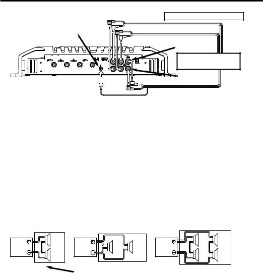
■ RCA cable connection
* : Commercially available parts
RCA cable ground terminal
(
 Left input
A.CH |
FILTER B.CH |
|
B.M.S. |
|
OPERATION |
INPUT SELECTOR |
. |
||
OFF HPF |
OFF |
|
OFF |
|
STEREO |
MONO(Lch) |
A B A |
A B SUB |
SUB |
HPF LPF |
|
REMOTE +12dB |
|
||||||
50 |
200 |
50 |
200 |
50 |
200 |
50 |
|
|
|
A.CH HPF |
B.CH HPF |
B.CH LPF |
SUB.CH |
|
|
||||
CENTER UNIT
(CD receiver, etc.)
FILTER FREQUENCY(Hz)
* |
( |
Right input |
|
||
|
|
RCA cable* |
■ Speaker Selection
•The rated input power of the speakers that are going to be connected should be greater than the maximum output power (in Watts) of the amplifier. Use of speakers having input power ratings that are less than the output power of the amplifier will cause smoke to be emitted as well as damage.
•The impedance of the speakers that are going to be connected should be 2Ω or greater (for stereo connections, amplifier SUB), or 4Ω or greater (for bridged connections). When more than one set of speakers are going to be used, calculate the combined impedance of the speakers and then connect suitable speakers to the amplifier.
2Ω |
|
4Ω |
4Ω |
|
8Ω |
8Ω |
|
2Ω |
|
4Ω |
4Ω |
4 Ω |
4 Ω |
4 Ω |
|
|
Combined impedance |
|
|
|
|
|
10 English
■ Speaker wire connection
FUSE(30Ax2)
30 |
30 |
BATT.
POWER IN
GND
Front Left speaker
Front Right speaker
&
^


SPEAKER |
Subwoofer |
P.CON OUTPUT |
|
A |
(L + R) |
|
^


Rear Right
speaker
Lead terminal*
Rear Left
(Stereo Connections)  speaker
(Bridged Connections)
Left speaker (Bridged)
&
^
FUSE(30Ax2)
BATT.
30 |
30 |
POWER IN
GND
SPEAKER |
BRIDGED |
P.CON OUTPUT |
|
A |
|
B |
|
^
Subwoofer
(L + R)
Right speaker (Bridged)
English 11

System examples
■ 5-channel system
(1) |
|
|
|
L |
A |
|
CENTER UNIT |
R |
|||||
|
|
|
|
L |
B |
|
5 |
|
|
7 |
R |
||
OPERATION |
|
INPUT SELECTOR |
L |
|
||
STEREO MONO(Lch) |
A B |
A A B SUB |
SUB |
|||
|
||||||
|
|
|
|
R |
||
(2) |
|
|
|
L |
A |
|
CENTER UNIT |
R |
|||||
|
|
|
|
L |
B |
|
5 |
|
|
7 |
R |
||
OPERATION |
|
INPUT SELECTOR |
L |
|
||
STEREO MONO(Lch) |
A B |
A A B SUB |
SUB |
|||
|
||||||
|
|
|
|
R |
||
(3) |
|
|
|
L |
A |
|
CENTER UNIT |
R |
|||||
|
|
|
|
L |
B |
|
5 |
|
|
7 |
R |
||
OPERATION |
|
INPUT SELECTOR |
L |
|
||
STEREO MONO(Lch) |
A B |
A A B SUB |
SUB |
|||
|
||||||
|
|
|
|
R |
||
■ 3-channel system |
|
|
||||
(1) |
|
|
|
L |
A |
|
CENTER UNIT |
R |
|||||
|
|
|
|
L |
B |
|
5 |
|
|
7 |
R |
||
OPERATION |
|
INPUT SELECTOR |
L |
|
||
STEREO MONO(Lch) |
A B |
A A B SUB |
SUB |
|||
|
||||||
|
|
|
|
R |
||
(2) |
|
|
|
L |
A |
|
CENTER UNIT |
R |
|||||
|
|
|
|
L |
B |
|
5 |
|
|
7 |
R |
||
OPERATION |
|
INPUT SELECTOR |
L |
|
||
STEREO MONO(Lch) |
A B |
A A B SUB |
SUB |
|||
|
||||||
|
|
|
|
R |
||
■ 4-channel system |
|
|
||||
(1) |
|
|
|
L |
A |
|
CENTER UNIT |
R |
|||||
|
|
|
|
L |
B |
|
5 |
|
|
7 |
R |
||
OPERATION |
|
INPUT SELECTOR |
L |
|
||
STEREO MONO(Lch) |
A B |
A A B SUB |
SUB |
|||
|
||||||
|
|
|
|
R |
||
(2) |
|
|
|
L |
A |
|
CENTER UNIT |
R |
|||||
|
|
|||||
|
|
|
|
L |
B |
|
5 |
|
|
7 |
R |
||
OPERATION |
|
INPUT SELECTOR |
L |
|
||
STEREO MONO(Lch) |
A B |
A A B SUB |
SUB |
|||
|
||||||
|
|
|
|
R |
||
L |
Front Left speaker |
|
A |
Front Right speaker |
|
R |
||
L |
Rear Left speaker |
|
B |
|
|
R |
Rear Right speaker |
|
SUB |
Subwoofer |
|
(L + R) |
||
|
1
A.CH FILTER B.CH
OFF |
|
HPF |
|
OFF |
|||
|
|
|
|
HPF |
LPF |
||
|
|
|
|
||||
|
|
|
|
|
|
|
|
L 


A
R 

L
B
R 


SUB
1

 Left speaker (Bridged)

 Right speaker (Bridged)
Subwoofer
(L + R)
A.CH FILTER B.CH
OFF |
|
HPF |
OFF |
|||
|
|
|
|
|
HPF |
LPF |
|
|
|
|
|
||
|
|
|
|
|
|
|
A |
L |
Tweeter |
|
R |
|||
|
|
BL 


 Woofer
R 


SUB 
 Subwoofer
1
A.CH FILTER B.CH
OFF |
|
HPF |
OFF |
|||||
|
|
|
|
HPF |
LPF |
|||
|
|
|
|
|||||
|
|
|
|
|
|
|
|
|
12 English

■ Tri-mode
|
|
|
C |
L |
|
|
|
L |
(High pass) |
|
|
|
A |
|
Refer to 5-channel system |
R |
|
||
|
|
|
C |
|
|
|
|
C |
L |
|
|
|
L |
(High pass) |
|
1 |
|
B |
|
|
|
R |
|
|
A.CH |
FILTER |
B.CH |
C |
|
OFF HPF |
|
OFF |
|
|
|
HPF LPF |
SUB |
|
|
|
|
Subwoofer |
||
|
|
|
||
|
|
|
|
|
Subwoofer
(L + R) (Bridged)
Subwoofer
(L + R) (Bridged)
●Principle of Tri-mode
Method of frequency band division using a coil and capacitor…in case of 6dB/oct. slope
|
Crossover Frequency |
Coil (L): Passes low frequencies and blocks high |
|||
0 dB |
|
frequencies. (Low pass) |
|||
|
|
||||
|
Capacitor (C): Passes high frequencies and blocks low |
||||
-3 dB |
|
||||
|
|
|
frequencies. (High pass) |
||
|
|
|
|
||
L |
C |
C= |
159000 |
(µF) |
|
|
Frequency |
fc x R |
fc=Cut of Frequency (Hz) |
||
|
L= |
159 x R |
(mH) |
R=Speaker Impedance (Ω) |
|
|
|
||||
|
|
|
fc |
|
|
●Example:
When it is required to set a crossover frequency of 120 Hz using speakers with an impedance of 4 ohms.
Prepare commercially-available coil and capacitor with the closest ratings to the results calculated from the formula above. The capacitor rating should be as close as possible to 331.25 (µF) and the coil rating should be as close as possible to 5.3 (mH).
2CAUTION
•If you wish to bridge-connect a speaker, the speaker impedance must be no less than 4 ohms. Connecting a speaker with an impedance lower than 4 ohms may damage the unit.
•Be sure to connect capacitors to speakers to which high frequencies will be passed. Failure to do so will result in a drop of the combined impedance with the subwoofer.
•Ensure that the withstand voltage and current ratings of the capacitors (C) and coils (L) are sufficient.
English 13

Troubleshooting Guide
What might appear to be a malfunction in your unit may just be the result of slight misoperation or miswiring. Before calling service, first check the following table for possible problems.
PROBLEM |
POSSIBLE CAUSE |
SOLUTION |
No sound. |
• Input (or output) cables are |
(No sound from one side.) |
disconnected. |
|
• Protection circuit may be |
|
activated. |
(Blown fuse.) |
• Volume is too high. |
|
• The speaker cord is shorted. |
•Connect the input (or output) cables.
•Check connections by referring to "Indicator".
•Replace the fuse and use lower volume.
•After check the speaker cord and fixing the cause of the short, replace the fuse.
The output level is too small (or too large).
The input sensitivity adjusting |
Adjust the control correctly |
control is not set to the correct |
referring to “Controls”. |
position. |
|
The sound quality is bad. (The sound is distorted.)
•The speakers wire are connected with wrong + / - polarity.
•A speaker wire is pinched by a screw in the car body.
•The switches may be set improperly.
•Connect them properly checking the + / - of the terminals and wires well.
•Connect the speaker wire again so that it is not pinched by anything.
•Set switches properly by referring to "System examples".
The external amplifier |
• The B.M.S. switch setting is |
controller (B.M.S.) will not |
incorrect. |
work. |
• The external amplifier control |
|
wire has come loose. |
•The B.M.S. switch is set to "REMOTE".
•Check that the external amplifier control wire is properly connected.
14 English
 Loading...