


DM-81
DIP METER
INTRODUCTION .............................................................................................................. |
1 |
Inductive coupling (Fig. 1A)........................................................................................... |
1 |
Capacitive coupling (Fig. 1B)......................................................................................... |
1 |
FEATURES ........................................................................................................................ |
3 |
SPECIFICATIONS............................................................................................................. |
4 |
CONTROLS ....................................................................................................................... |
5 |
PRECAUTIONS ................................................................................................................. |
6 |
Battery and Oscillation Coil Loading ............................................................................. |
6 |
Obtaining a Dip Point ..................................................................................................... |
6 |
Measuring Transistor Resonant Circuits......................................................................... |
6 |
Caution in Measuring Transmitters ................................................................................ |
6 |
Caution in Motor Pointer Deflection Change ................................................................. |
7 |
APPLICATIONS ................................................................................................................ |
7 |
Use as a Dip Meter.......................................................................................................... |
7 |
Other Frequency Measurements ..................................................................................... |
8 |
Resonant circuit measurement .................................................................................... |
8 |
Use of the capacitive probe......................................................................................... |
8 |
Antenna resonant frequency measurement ............................................................... |
10 |
Use as a Signal Generator ......................................................................................... |
11 |
Use as Crystal Checker and Marker Generator......................................................... |
11 |
Use as an Absorption Frequency Meter.................................................................... |
12 |
Use as a Field-Strength Meter................................................................................... |
13 |
Capacitance and Inductance Measurements ............................................................. |
14 |
ADJUSTMENT ................................................................................................................ |
17 |
VR1: 01 Bias adj........................................................................................................... |
17 |
VR2: Meter zero adj...................................................................................................... |
17 |
VR3: Sensitivity adj...................................................................................................... |
17 |
VR4: Battery voltage check adj. ................................................................................... |
17 |
PARTS AND SERVICE................................................................................................... |
17 |
Ordering Spare Parts ..................................................................................................... |
17 |
Service........................................................................................................................... |
17 |
PARTS LIST..................................................................................................................... |
18 |
PRINTED CIRCUIT BOARDS ....................................................................................... |
22 |
SCHEMATIC DIAGRAM ............................................................................................... |
24 |
KENWOOD DM-81
KENWOOD DM-81
INTRODUCTION
A dip meter is used for adjustment of radio equipment and antennas. The DM-81 is a self-excited oscillator designed for external coupling to the equipment being tested. It features both inductive and capacitive coupling for measuring enclosed coils and toroidal coils (patent pending). This is not possible with conventional testing instruments.
The DM-81 has the following two functions:
Inductive coupling
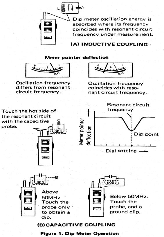
As shown (Figure 1A), place the coil unit of the dip meter in close proximity to the circuit being measured.
Adjust the dial. When the dip meter oscillation frequency coincides with the resonant frequency (tuned circuit), oscillating energy is absorbed by the circuit, thus decreasing the oscillation strength.
This strength is indicated on the meter. The pointer swings back momentarily at the resonant point. Since the meter pointer dips at a tuned point, this instrument is called a dip meter.
Capacitive coupling
This is a special feature of the DM-81 which is not found in any other dip meter. The resonant frequency can be checked simply by touching the capacitance probe to the hot side of the resonant circuit under test, instead of coupling the DM-81's coil and measuring inductively. The frequency is read directly on the dial. See Figure 1B.
Radio equipment is miniaturized and most coils are enclosed in metal shields. Also, toroidal coils are used in many types of radio equipment, and these coils do not couple to conventional dip meters. The DM-81 has solved this problem.
1
KENWOOD DM-81
2
KENWOOD DM-81
FEATURES
1.Measurable frequency range is 700kHz to 25OMHz in seven bands.
2.All seven dip meter coils, capacitive probe, earphone and ground clip lead, can be carried within the unit for easy transport and storage.
3.Convenient for both in indoor and outdoor measurements, all solid-state and builtin battery.
4.HC-25U and FT-243 sockets enable use as a crystal checker and marker generator.
5.Amplitude modulation is convenient in aligning receivers when using your DM81 as a signal generator. Also, when used as the marker generator, amplitude modulation is helpful in precisely calibrating the dial scale even for a receiver having no BFO.
6.An FET and transistor are used in the meter circuit to provide extremely good sensitivity.
7.As an absorption frequency meter, your DM-81 is used both to align transmitters and measure field strength.
8.An earphone plug allows you to monitor transmitted signals.
9.A capacitive probe allows measurements without removing coil shields.
10.It is possible to measure resonant circuit frequencies of toroidal coils. This is not possible with conventional dip meters.
3
KENWOOD DM-81
SPECIFICATIONS
700kHz - 250MHz (± 3%) A band 0.7 - 1.6MHz (± 3%) B band 1.5 - 3.6MHz (± 3%)
Frequency range:
C band 3.0 - 7.4MHz (± 3%)
D band 6.9 - 17.5MHz (± 3%)
E band 17 - 42MHz (± 3%)
F band 41 - 110MHz (± 3%)
G band 83 - 250MHz (± 3%)
Modulation:
Power requirements: Power consumption: Semi-conductors:
Crystal oscillator element to be used:
RF search terminal:
Earphone terminal:
Dimensions:
Weight:
Accessories:
1 kHz (sine wave)
Battery, 9V(006P)
9 mA
1 FET, 3 transistors, 3 diodes
HC-25U and FT-243
For measuring resonant frequency (capacitive coupling) and checking RF voltage using the supplied probe.
Accepts crystal earphone with 3.5ø plug for monitor ing modulated tone.
70W x 180H x 45D (mm)
Approx. 690g (with accessories)
(1)Coils, A-G bands — 7 pieces
(2)Probe — 1 piece
(3)Ground clip — 1 piece
(4)Crystal earphone — 1 piece
(5)Battery, 006P — 1 piece
CAUTION: Do not apply a voltage exceeding 500V (DC + AC peak) to the probe.
4

KENWOOD DM-81
CONTROLS
5
KENWOOD DM-81
PRECAUTIONS
Battery and Oscillation Coil Loading
Taking the coil compartment out, you will find a battery snap connector inside the unit. Fit the snap to the battery. First lay the battery take-out ribbon into the battery holder, then install the battery in place. Place the supplied oscillation coils into the coil compartment and reinstall into the dip meter main body.
Verify that the battery is serviceable before operating your DM-81. First, turn the POWER switch on. Set the FUNCTION switch to "BATT CHECK". The battery is usable as long as the meter pointer is within the "B.C" zone. A low battery results in weak or unstable oscillation, no oscillation, or frequency error. Replace the battery when weak.
After use, be sure to turn the POWER switch off. If your DM-81 will not be used for a long period of time, remove the battery. You can easily remove it by pulling the take-out ribbon toward you. Never remove the case screws.
Obtaining a Dip Point
The closer the dip meter is brought to the resonant circuit being checked, the tighter the two are coupled and the deeper the dip point. However, the tuning point becomes so broad that you cannot find the correct resonant frequency. Therefore, it is advisable to move the dip meter a little away from the circuit.
Note that the A band has a large pull-in effect and therefore the dip point is broad.
Measuring Transistor Resonant Circuits
There is no load problem in measuring vacuum tube resonant circuits. In measuring some resonant (tuning) circuits in transistorized transmitters and receivers, the resonant point cannot always be found by the dipping load. In this event, temporarily disconnect the transistor or operate the given resonant circuit with power on and measure by absorption.
Caution in Measuring Transmitters
Your DM-81 is usable as an absorption frequency meter in measuring transmitter power amplifier tank circuits and similar stages producing high RF energy. In rneasurement, do not abruptly bring the dip meter close to the circuit as the transistors and other parts in the dip meter could be destroyed by excess RF energy. Bring it near the circuit slowly while observing the meter pointer.
6
 Loading...