


DDX8017
DDX7017
DDX7047
MONITOR WITH DVD RECEIVER
INSTALLATION MANUAL
MONITEUR AVEC REPTEUR DVD
MANUEL D'INSTALLATION
MONITOR CON RECEPTOR DVD
MANUAL DE INSTALACION
MONITOR COM RECEPTOR DVD
MANUAL DE INSTALAÇAO
© B54-4467-00/00 (KV/RV)

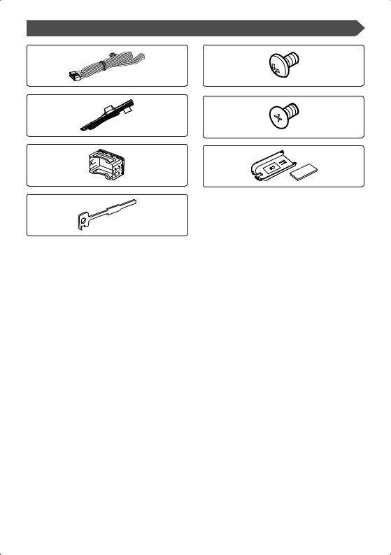
Accessories
1 |
5 |
..........1 .......... |
6 |
2 |
6 |
..........1 .......... |
6 |
3 |
7 |
..........1 .......... |
1 |
4
..........2
2 | English

Installation Procedure
1.To prevent a short circuit, remove the key from the ignition and disconnect the - battery.
2.Make the proper input and output wire connections for each unit.
3.Connect the speaker wires of the wiring harness.
4.Connect the wiring harness wires in the following order: ground, battery, ignition.
5.Connect the wiring harness connector to the unit.
6.Install the unit in your car. 7.Reconnect the - battery. 8.Press the reset button.
2WARNING
•If you connect the ignition wire (red) and the battery wire (yellow) to the car chassis (ground), you may cause a short circuit, that in turn may start a fire. Always connect those wires to the power source running through the fuse box.
•Do not cut out the fuse from the ignition wire (red) and the battery wire (yellow). The power supply must be connected to the wires via the fuse.
2CAUTION
•If your car’s ignition does not have an ACC position, connect the ignition wires to a power source that can be turned on and off with the ignition key. If you connect the ignition wire to a power source with a constant voltage supply, as with battery wires, the battery may die.
•If the console has a lid, make sure to install the unit so that the faceplate will not hit the lid when closing and opening.
•If the fuse blows, first make sure the wires aren’t touching to cause a short circuit, then replace the old fuse with one with the same rating.
•Insulate unconnected wires with vinyl tape or other similar material. To prevent a short circuit, do not remove the caps on the ends of the unconnected wires or the terminals.
•Connect the speaker wires correctly to the terminals to which they correspond. The unit may be damaged or fail to work if you share the - wires or ground them to any metal part in the car.
•When only two speakers are being connected to the system, connect the connectors either to both the front output terminals or to both the rear output terminals (do not mix front and rear). For example,
if you connect the + connector of the left speaker to a front output terminal, do not connect the - connector to a rear output terminal.
•After the unit is installed, check whether the brake lamps, blinkers, wipers, etc. on the car are working properly.
•Mount the unit so that the mounting angle is 30° or less.
English | 3

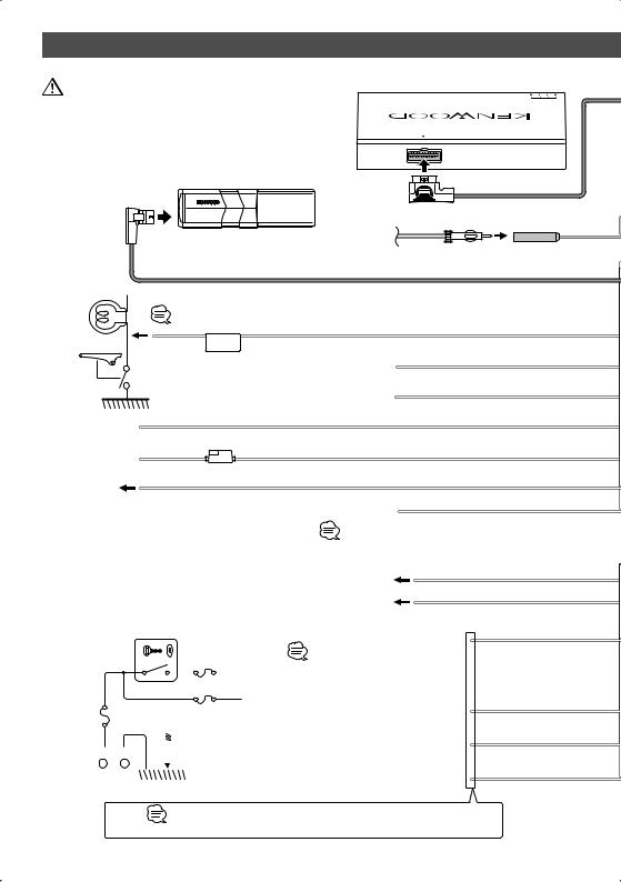
Connection
If you connect the ignition wire (red) and the battery wire (yellow) to the car chassis (ground), you may cause a short circuit, that in turn may start a fire. Always connect those wires to the power source running through the fuse box.
TV tuner (Optional)
TVANTENNAINPUT
TOMONITORUNIT
Disc Changer etc.(Optional)
C 
B 
Antenna Cord |
FM/AM antenna input |
|||
|
|
|
|
|
Connection cable (Included in the disc changer)
Connect to the vehicle's parking brake detection switch harness using the supplied relay connector.
For the sake of safety, be sure to connect the parking sensor.
PRK SW |
Parking sensor wire (Green) |
|
Reveres sensor wire (Pink)
To Vehicle's reverse lamp harness
Dimmer control wire (Orange/White)
To car light control switch
Ground wire (Black) - (To car chassis)
Battery wire |
( 5A ) |
|
(Yellow) |
||
|
Ignition wire (Red)
A 
Steering remote control input To Steering remote (Light Blue/Yellow)
If no connections are made, do not let the cable come out from the tab.
Battery wire (Yellow)
B 
C |
Ground wire (Black) - (To car chassis) |
|
|
Ignition key |
Connect to the terminal that is grounded when either |
|
|
switch |
||
|
|
the telephone rings or during conversation. |
|
|
|
|
|
|
|
ACC |
To connect the Kenwood navigation system, |
|
|
A |
|
|
|
consult your navigation manual. |
|
Car fuse |
|
B |
Depending on what antenna you are using, |
|
connect either to the control terminal of the |
||
box |
|
Car fuse box |
motor antenna, or to the power terminal for the |
(Main fuse) |
|
|
booster amplifier of the film-type antenna. |
|
C |
When using the optional power amplifier, |
|
+ |
connect to its power control terminal. |
||
– |
|
|
|
Battery |
To "EXT.AMP.CONT." terminal of the amplifier |
|
having the external amp control function. |
||
|
Mute wire (Brown)
Motor antenna control wire (Blue)
Power control wire (Blue/White)
External amplifier control wire (Pink/Black)
If no connections are made, do not let the cable come out from the tab.
4 | English

Connection cable (Included in the TV tuner)
IConnection cable
Rear view (Included in the
Navigation system)
MUTE
ANT. CONT
P CONT
EXT.CONT
Wiring harness |
(Accessory 1) |
Wiring harness (Accessory 2)
REVERSE
ILLUMI
Navigation System (Optional)
REMO.CONT
L |
White/Black |
|
|
FRONT |
|
||
|
To front left speaker |
||
|
+ |
||
|
|
||
|
White |
|
|
R |
Gray/Black |
|
|
FRONT |
|
||
+ |
To front right speaker |
||
|
|||
|
|
||
|
Gray |
|
|
L |
Green/Black. |
|
|
REAR |
|
||
|
To rear left speaker |
||
|
+ |
||
|
|
||
|
Green |
|
|
R |
Purple/Black |
|
|
REAR |
|
||
|
To rear right speaker |
||
|
+ |
||
|
|
||
|
Purple |
|
English | 5
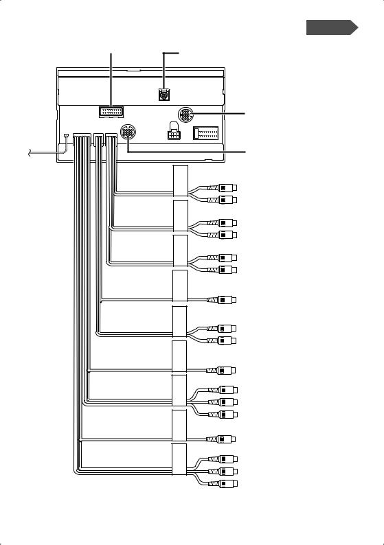
System Connection |
(DDX8017/DDX7017) |
To TV Tuner unit |
Do not connect. |
|
To Navigation System
FRONT |
REAR |
SUB WOOFER |
CENTER |
AV OUT |
REAR VIEW CAMERA |
AV IN 2 |
AV OUT |
AV IN 1 |
To Disc Changer etc.
■Front Preout
•Audio left output (White)
•Audio right output (Red)
■Rear Preout
•Audio left output (White)
•Audio right output (Red)
■Subwoofer Preout
•Audio left output (White)
•Audio right output (Red)
■Center Preout (DDX8017 only)
■Audio/Visual Output
•Audio left output (White)
•Audio right output (Red)
■Rear View Camera Input
•Visual input (Yellow)
■Audio/Visual input 2
•Visual input (Yellow)
•Audio left input (White)
•Audio right input (Red)
■Audio/Visual Output
•Visual output (Yellow)
■Audio/Visual input 1
•Visual input (Yellow)
•Audio left input (White)
•Audio right input (Red)
6 | English
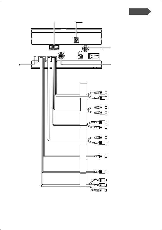
System Connection |
(DDX7047) |
To TV Tuner unit |
Do not connect. |
|
To Navigation System
To Disc Changer etc.
REARCAMERAVIEW AV OUT WOOFERSUB REAR FRONT
AV OUT |
AV IN
■Front Preout
•Audio left output (White)
•Audio right output (Red)
■Rear Preout
•Audio left output (White)
•Audio right output (Red)
■Subwoofer Preout
•Audio left output (White)
•Audio right output (Red)
■Audio/Visual Output
•Audio left output (White)
•Audio right output (Red)
■Rear View Camera Input
•Visual input (Yellow)
■Audio/Visual Output
•Visual output (Yellow)
■Audio/Visual input
•Visual input (Yellow)
•Audio left input (White)
•Audio right input (Red)
English | 7
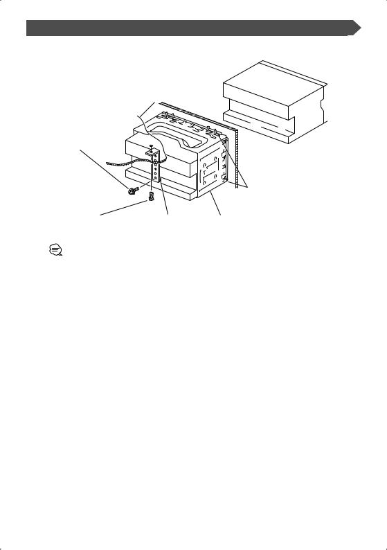
Installation for Monitor/Player Unit
Firewall or metal support
Screw (M4X8) (commercially available)
Bend the tabs of the mounting sleeve with a screwdriver or similar utensil and attach it in place.
Self-tapping screw |
Metal mounting strap |
Accessory 3 |
(commercially available) |
(commercially available) |
|
Make sure that the unit is installed securely in place. If the unit is unstable, it may malfunction (eg, the sound may skip).
8 | English
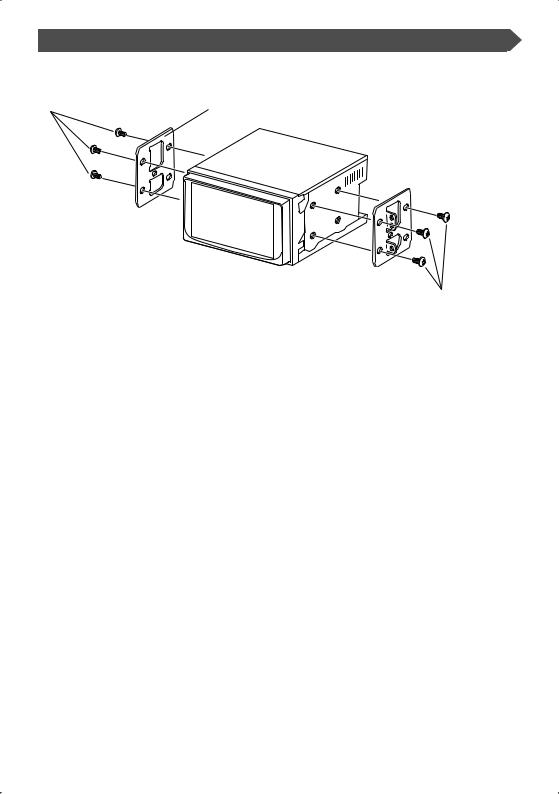
Installing in Japanese-Made Cars
■ Installation on Toyota, Nissan or Mitsubishi Car using Brackets
Accessory 5(M5x6mm)
or Accessory 6(M5x7mm)
Car Bracket
Accessory 5(M5x6mm) or Accessory 6(M5x7mm)
English | 9

Installation of Remote control unit
■ Install the remote control unit holder (Accessory 7).
Double-stick tape |
Remote control holder 7 |
(included) |
To prevent the Remote control unit from dropping down under your foot, install it using the Remote control unit holder. If the Remote control unit drops down under driving pedals, it will interfere with your driving and may result in a traffic accident.
10 | English
Removing Monitor Unit
■ Removing the Hard Rubber Frame (escutcheon)
1. Engage the catch pins on the removal tool 4 and remove the two locks on the lower level. Lower the frame and pull it forward as shown in the figure.
2.When the lower level is removed, remove the upper two locations.
The frame can be removed from the top side in the same manner.
Removal Tool (Accessory 4)
Catch
Lock
■Removing the Unit
1.Remove the hard rubber frame by referring to the removal procedure in the section <Removing the Hard Rubber Frame>.
2.Remove the Hex-head screw with integral washer (M4 × 8) on the back panel.
3.Insert the two removal tools 4 deeply into the slots on each side, as shown.
4.Lower the removal tool toward the bottom, and pull out the unit halfway while pressing towards the inside.
Be careful to avoid injury from the catch pins on the removal tool.
5.Pull the unit all the way out with your hands, being careful not to drop it.
Removal Tool (Accessory 4)
English | 11
Accessoires
1 |
5 |
..........1 .......... |
6 |
2 |
6 |
..........1 .......... |
6 |
3 |
7 |
..........1 .......... |
1 |
4
..........2
12 | Français

Procédure d’installation
1.Afin d’empêcher un court circuit, retirez la clé du contact et déconnectez la batterie -.
2.Effectuez correctement les connexions d'entrée et sortie de chaque appareil.
3.Connectez les câbles de haut-parleur du faisceau de câbles.
4.Connectez les fils du câblage de distribution électrique dans l’ordre suivant : masse, batterie, contact.
5.Connectez le connecteur du câblage de distribution électrique à l’appareil.
6.Installez l’appareil dans votre voiture.
7.Reconnectez la batterie -.
8.Appuyez sur la touche de réinitialisation.
2ATTENTION
•Si vous connectez le câble d’allumage (rouge) et le câble de batterie (jaune) au châssis de la voiture (masse), vous risquez de causer un court-circuit qui peut provoquer un incendie. Connectez toujours ces câbles à la source d’alimentation de la boîte à fusible.
•N'isolez pas le fusible du câble d'allumage (rouge) ni du câble de batterie (jaune). L'alimentation doit être connectée aux câbles par l'intermédiaire du fusible.
2AVERTISSEMENT
•Si l'allumage de votre voiture ne dispose pas d'une position ACC, connectez les câbles d'allumage à une source d'alimentation pouvant être activée et inactivée avec la clé de contact. Si vous connectez le fil de contact à une source d’alimentation avec une alimentation de tension constante, comme avec des fils de batterie, la batterie peut mourir.
•Si la console a un couvercle, assurez-vous d’installer l’unité de manière à ce que la façade ne touche pas le couvercle lors de l’ouverture et de la fermeture.
•Si le fusible saute, assurez-vous d’abord que les fils ne se touchent pas et n’entraînent pas de courtcircuit, puis remplacez le fusible grillé par un fusible neuf de même capacité.
•Isolez les câbles non-connectés avec un ruban adhésif en vinyle ou autre matériel similaire. Afin d’empêcher tout court-circuit, ne retirez pas les capuchons présents aux extrémités des fils ou des bornes non connectés.
•Connectez les fils d’enceinte correctement aux bornes correspondantes. L’appareil peut être endommagé ou ne pas fonctionner si vous partagez les fils - ou si vous les mettez à la masse sur une partie métallique de la voiture.
•Lorsque deux enceintes seulement sont connectées au système, connectez les connecteurs soit aux deux bornes de sortie avant, soit aux deux bornes de sortie arrière (ne mélangez pas l’avant et l’arrière). Par exemple, si vous connectez le connecteur +
de l’enceinte gauche à une borne de sortie avant, ne connectez pas le connecteur - à une borne de sortie arrière.
•Après avoir installé l’appareil, vérifiez si les feux de freinage, les indicateurs, les clignotants, etc. de la voiture fonctionnent correctement.
•Montez l’unité de façon à ce que l’angle de montage soit de 30° ou moins.
Français | 13
Connexion
Si vous connectez le câble d’allumage (rouge) et le câble de batterie (jaune) au châssis de la voiture (masse), vous risquez de causer un court-circuit qui peut provoquer un incendie.
Connectez toujours ces câbles à la source d’alimentation de la boîte à fusible.
Syntoniseur (en option)
TVANTENNAINPUT
TOMONITORUNIT
Changeur de disque etc. (en option)
Entrée de
Cordon de l'antenne l’antenne AM/FM
Câble de connexion (inclus dans le changeur de disque)
Connectez-le au commutateur de détection de frein à main du véhicule à l'aide du connecteur de relais fourni.
Par mesure de sécurité, connecter le câble du détecteur de stationnement.
PRK SW Câble de frein à main (Vert)
Câble de marche arrière (Rose)
Vers le faisceau du feu de marche arrière du véhicule
Câble de commande du gradateur
(Orange/Blanc)
Au commutateur d’éclairage de la voiture
Câble de masse (Noir) - (Au châssis de la voiture)
C 
Câble de batterie ( 5A )
(Jaune)
B 
|
|
A |
|
|
|
Câble d’allumage (Rouge) |
|
|
|
|
||||||||||||
|
|
|
|
|
|
|
|
|
|
|
|
|
|
|
|
|
|
Entrée de la commande de direction |
||||
|
|
|
|
|
|
|
|
|
|
|
|
|
|
|
|
|
|
|
Vers la commande de direction |
(Bleu Clair/Jaune) |
|
|
|
|
|
|
|
|
|
|
|
|
|
|
|
|
|
|
|
|
|
|
Si aucune connexion n'est faite, ne |
|
|
|
|
|
|
|
|
|
|
|
|
|
|
|
|
|
|
|
|
|
|
laissez pas le câble sortir à l'extérieur. |
|
|
|
|
|
|
|
|
|
|
|
|
|
|
|
|
|
|
|
|
|
|
B |
Câble de batterie (Jaune) |
|
|
|
|
|
|
|
|
|
|
|
|
|
|
|
|
|
|
|
|
|
Câble de masse (Noir) - (Au châssis de |
||
|
|
|
|
|
|
|
|
|
|
|
|
|
|
|
|
|
|
|
|
C |
la voiture) |
|
|
|
|
|
|
|
|
|
|
|
|
|
|
|
|
|
|
|
|
|
|
|
|
|
|
|
|
|
|
|
Interrupteur |
|
|
|
|
Connectez à une prise qui est à la masse soit quand le |
Câble de sourdine |
|||||||||
|
|
|
|
|
|
|
d’allumage |
|
|
|
|
|
téléphone sonne soit pendant une conversation. |
(Brun) |
||||||||
|
|
|
|
|
|
|
|
|
|
|
|
|
|
|
|
|
Allumage |
Pour connecter le système de navigation |
|
|||
|
|
|
|
|
|
|
|
|
|
|
|
|
|
|
|
|
|
A |
|
|
||
|
|
|
|
|
|
|
|
|
|
|
|
|
|
|
|
|
|
|
Kenwood, consultez le manuel du |
Câble de commande du |
||
|
|
|
|
|
|
|
|
|
|
|
|
|
|
|
|
|
|
|||||
|
|
|
|
|
|
|
|
|
|
|
|
|
|
|
|
|
|
|
|
système de navigation. |
||
à fusibles de |
|
|
|
|
|
|
|
|
|
|
|
|
|
|
|
|
|
B |
|
Selon l'antenne que vous utilisez, |
moteur d'antenne |
|
|
|
|
|
|
|
|
|
|
|
|
|
|
|
|
|
|
|
(Bleu) |
||||
la voiture |
|
|
|
|
|
|
|
|
|
|
|
|
|
|
|
|
|
|
||||
|
|
|
|
|
|
|
|
|
|
|
|
|
Boîte à |
|
connectez à la prise de commande du moteur |
Câble de commande de |
||||||
Boîte |
|
|
|
|
|
|
|
|
|
|
|
|
|
|
||||||||
|
|
|
|
|
|
|
|
|
|
|
|
|
|
d'antenne ou à la prise d'alimentation du |
||||||||
(Fusible |
|
|
|
|
|
|
|
|
|
|
|
|
|
fusibles de |
|
l’alimentation |
||||||
|
|
|
|
|
|
|
|
|
|
|
|
|
|
préamplificateur de l'antenne de type film. |
||||||||
principal) |
|
|
|
|
|
|
|
|
|
la voiture |
|
|
|
(Bleu/Blanc) |
||||||||
|
|
|
|
|
|
|
|
|
|
|
|
C |
|
Lors de l'utilisation de l'amplificateur de puissance optionnel, |
Câble de commande |
|||||||
|
+ |
|
|
– |
|
|
|
|
|
|
|
|
|
connectez à sa prise de commande d'alimentation. |
||||||||
|
|
|
|
|
|
|
|
|
|
|
|
|
|
|
|
|
|
de l'amplificateur |
||||
|
Batterie |
|
|
|
Vers le terminal "EXT.AMP.CONT." de l’amplificateur ayant la |
externe (Rose/Noir) |
||||||||||||||||
|
|
|
|
|
||||||||||||||||||
|
|
|
|
|
|
|
|
|
|
|
|
|
|
|
|
|
|
|
|
fonction de contrôle de l’amp. extérieur. |
|
|
Si aucune connexion n'est faite, ne laissez pas le câble sortir à l'extérieur.
14 | Français
 Loading...