


MICRO COMPONENT SYSTEM
UX-HB4 –Consists of CA-UXHB4 and SP-UXHB4
INSTRUCTIONS
LVT1266-001A
[B]
Warnings, Cautions and Others
IMPORTANT for the U.K.
DO NOT cut off the mains plug from this equipment. If the plug fitted is not suitable for the power points in your home or the cable is too short to reach a power point, then obtain an appropriate safety approved extension lead or consult your dealer.
BE SURE to replace the fuse only with an identical approved type, as originally fitted.
If nonetheless the mains plug is cut off ensure to remove the fuse and dispose of the plug immediately, to avoid a possible shock hazard by inadvertent connection to the mains supply.
If this product is not supplied fitted with a mains plug then follow the instructions given below:
IMPORTANT:
DO NOT make any connection to the terminal which is marked with the letter E or by the safety earth symbol or coloured green or green-and-yellow.
The wires in the mains lead on this product are coloured in accordance with the following code:
Blue : Neutral Brown : Live
As these colours may not correspond with the coloured markings identifying the terminals in your plug proceed as follows:
The wire which is coloured blue must be connected to the terminal which is marked with the letter N or coloured black.
The wire which is coloured brown must be connected to the terminal which is marked with the letter L or coloured red.
IF IN DOUBT—CONSULT A COMPETENT ELECTRICIAN.
CAUTION— (STANDBY/ON) button!
Disconnect the mains plug to shut the power off completely (all lamps and indications go off). The  (STANDBY/ON) button in any position does not disconnect the mains line.
•When the unit is on standby, the STANDBY lamp lights red.
•When the unit is turned on, the STANDBY lamp goes off.
The power can be remote controlled.
CAUTION
To reduce the risk of electrical shocks, fire, etc.:
1.Do not remove screws, covers or cabinet.
2.Do not expose this appliance to rain or moisture.
CAUTION
•Do not block the ventilation openings or holes.
(If the ventilation openings or holes are blocked by a newspaper or cloth, etc., the heat may not be able to get out.)
•Do not place any naked flame sources, such as lighted candles, on the apparatus.
•When discarding batteries, environmental problems must be considered and local rules or laws governing the disposal of these batteries must be followed strictly.
•Do not expose this apparatus to rain, moisture, dripping or splashing and that no objects filled with liquids, such as vases, shall be placed on the apparatus.
IMPORTANT FOR LASER PRODUCTS
1.CLASS 1 LASER PRODUCT
2.CAUTION: Do not open the top cover. There are no user serviceable parts inside the unit; leave all servicing to qualified service personnel.
3.CAUTION: Visible and invisible laser radiation when open and interlock failed or defeated. Avoid direct exposure to beam.
4.REPRODUCTION OF LABEL: CAUTION LABEL, PLACED INSIDE THE UNIT.
CAUTION -
VORSICHT !
VARNING -
ADVARSEL -USYNLIG LASERSTRÅLING VED ÅBNING NÅR
SIKKERHEDSAFBRYDERE ER UDE AF FUNKTION. UNDGÅ
UDSÆTTELSE FOR STRÅLING.
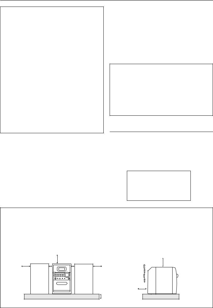
CAUTION: Proper Ventilation
To avoid risk of electric shock and fire, and to prevent damage, locate the apparatus as follows:
1 Front:
No obstructions and open spacing. 2 Sides/ Top/ Back:
No obstructions should be placed in the areas shown by the dimensions below.
3 Bottom:
Place on the level surface. Maintain an adequate air path for ventilation by placing on a stand with a height of 10 cm or more.
Front view |
15 cm |
Side view |
1 cm |
1 cm |
15 cm |
15 cm |
15 cm |
|
|
|
15 cm |
|
|
10 cm |
|
UX-HB4 |
UX-HB4 |
G-1 |
|
|
SAFETY INSTRUCTIONS
“SOME DOS AND DON’TS ON THE SAFE USE OF EQUIPMENT”
This equipment has been designed and manufactured to meet international safety standards, but like any electrical equipment, care must be taken if you are to obtain the best results and safety is to be assured.
Do read the operating instructions before you attempt to use the equipment.
Do ensure that all electrical connections (including the mains plug, extension leads and interconnections between pieces of equipment) are properly made and in accordance with the manufacturer’s instructions. Switch off and withdraw the mains plug when making or changing connections.
Do consult your dealer if you are ever in doubt about the installation, operation or safety of your equipment.
Do be careful with glass panels or doors on equipment.
DON’T continue to operate the equipment if you are in any doubt about it working normally, or if it is damaged in any way
—switch off, withdraw the mains plug and consult your dealer.
DON’T remove any fixed cover as this may expose dangerous voltages.
DON’T leave equipment switched on when it is unattended unless it is specifically stated that it is designed for unattended operation or has a standby mode.
Switch off using the switch on the equipment and make sure that your family know how to do this.
Special arrangements may need to be made for infirm or handicapped people.
DON’T use equipment such as personal stereos or radios so that you are distracted from the requirements of traffic safety. It is illegal to watch television whilst driving.
DON’T listen to headphones at high volume as such use can permanently damage your hearing.
DON’T obstruct the ventilation of the equipment, for example with curtains or soft furnishings.
Overheating will cause damage and shorten the life of the equipment.
DON’T use makeshift stands and NEVER fix legs with wood screws—to ensure complete safety always fit the manufacturer’s approved stand or legs with the fixings provided according to the instructions.
DON’T allow electrical equipment to be exposed to rain or moisture.
ABOVE ALL
—NEVER let anyone, especially children, push anything into holes, slots or any other opening in the case—this could result in a fatal electrical shock.
—NEVER guess or take chances with electrical equipment of any kind—it is better to be safe than sorry!
G-2
Introduction
We would like to thank you for purchasing one of our JVC products. Before operating this unit, read this manual carefully and thoroughly to obtain the best possible performance from your unit, and retain this manual for future reference.
About This Manual
This manual is organized as follows:
•This manual mainly explains operations using the buttons on the remote control.
You can use the buttons both on the remote control and on the unit for the same operations if they have the same or similar names (or marks), unless mentioned otherwise.
•Basic and common information that is the same for many functions is grouped in one place, and is not repeated for each procedure. For instance, we do not repeat the information about turning on/off the unit, setting the volume, changing the sound effects, and others, which are explained in the section “Common Operations” on pages 9 to 11.
•The following symbols are used in this manual:
Gives you warning and caution to prevent damage or risk of fire/electric shock.
In addition, we put information here about conditions which will prevent getting the best possible performance from the unit.
Gives you information and hints you need to know.
Power sources
•When unplugging the unit from the wall outlet, always pull on the plug, not the AC power cord.
DO NOT handle the AC power cord with wet hands.
Moisture condensation
Moisture may condense on the lenses inside the unit in the following cases:
•After starting to heat the room.
•In a damp room.
•If the unit is brought directly from a cold to a warm place. Should this occur, the unit may malfunction. In this case, leave the unit turned on for a few hours until the moisture evaporates, unplug the AC power cord, then plug it in again.
Others
•Should any metallic object or liquid fall into the unit, unplug the AC power cord and consult your dealer before operating any further.
•If you are not going to operate the unit for an extended period of time, unplug the AC power cord from the wall outlet.
•Rating label is placed on the exterior of the bottom.
DO NOT disassemble the unit since there are no user serviceable parts inside.
Precautions
Installation
•Install in a place which is level, dry and neither too hot nor too cold—between 5˚C and 35˚C.
•Install the unit in a location with adequate ventilation to prevent internal heat buildup.
•Leave sufficient distance between the unit and the TV.
•Keep the speakers away from the TV to avoid interference with TV.
DO NOT install the unit in a location near heat sources, or in a place subject to direct sunlight, excessive dust or vibration.
If anything goes wrong, unplug the AC power cord and consult your dealer.
1

Contents
Location of the Buttons and Controls ....................... |
3 |
Main Unit ............................................................................... |
3 |
Remote Control ..................................................................... |
5 |
Getting Started ............................................................ |
6 |
Unpacking .............................................................................. |
6 |
Connecting DAB Antenna ..................................................... |
6 |
Connecting AM (MW) and FM Antennas ............................. |
7 |
Connecting Speakers ............................................................. |
7 |
Connecting Other Equipment ................................................ |
8 |
Putting the Batteries into the Remote Control ....................... |
8 |
Common Operations .................................................. |
9 |
Setting the Clock ................................................................... |
9 |
Turning On the Power ......................................................... |
10 |
Turning Off the Unit Automatically (Auto Standby) ........... |
10 |
Selecting the Source ............................................................ |
10 |
Adjusting the Volume .......................................................... |
10 |
Fade-Out Muting (FADE MUTING) .................................. |
11 |
Selecting the Sound Modes ................................................. |
11 |
Reinforcing the Bass Sound ................................................ |
11 |
Checking the Clock Time During Play ................................ |
11 |
Playing Back Discs .................................................... |
12 |
Playing Back the Entire Disc—Normal Play ...................... |
12 |
Basic Disc Operations ......................................................... |
13 |
Programming the Track Playing Order—Program Play ...... |
14 |
Repeating Tracks—Repeat Play .......................................... |
15 |
Playing at Random—Random Play ..................................... |
15 |
Displaying the Remaining Time during Playback |
|
(for Audio CD) .................................................................... |
15 |
Displaying the Tag Information (for MP3 disc) .................. |
15 |
Playing Back Tapes ................................................... |
16 |
Playing Back a Tape ............................................................ |
16 |
Listening to DAB Broadcast .................................... |
17 |
What is DAB? ...................................................................... |
17 |
Initial Scanning .................................................................... |
17 |
Tuning in to a Station .......................................................... |
18 |
Presetting Stations ............................................................... |
18 |
Tuning in to a Preset Station ................................................ |
18 |
Arranging and Sorting the Station List ................................ |
19 |
Changing the Dynamic Range Control level (DRC) ........... |
19 |
Changing the Display Information ...................................... |
20 |
Refreshing the Station List .................................................. |
20 |
Listening to FM and AM (MW) Broadcasts .......... |
21 |
Tuning in to a Station .......................................................... |
21 |
Presetting Stations ............................................................... |
21 |
Tuning in to a Preset Station ................................................ |
22 |
Receiving FM Stations with RDS ....................................... |
22 |
Changing the RDS Information ........................................... |
23 |
Searching for Programs by PTY Codes (PTY Search) ....... |
23 |
Using an External Equipment ................................. |
24 |
Listening to the External Equipment ................................... |
24 |
Recording .................................................................. |
25 |
Recording on a Tape ............................................................ |
25 |
Recording Discs—Disc Synchronized Recording ............... |
26 |
Using the Timers ....................................................... |
27 |
Using Daily Timer and Recording Timer ............................ |
27 |
Using Snooze Timer ............................................................ |
28 |
Using Sleep Timer ............................................................... |
29 |
Maintenance .............................................................. |
30 |
Troubleshooting ........................................................ |
31 |
Specifications ............................................................. |
32 |
2
Location of the Buttons and Controls
Become familiar with the buttons and controls on your unit.
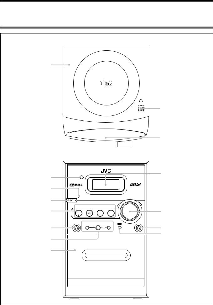
Main Unit
Top view
1
COMPACT
DIGITAL AUDIO
OPEN
2
D A I L Y T I M E R / S N O O Z E
Front view
4 |
|
|
|
|
|
|
5 |
|
|
|
|
|
|
6 |
STANDBY |
|
|
|
|
VOLUME |
|
|
|
|
|
||
|
|
|
|
– |
+ |
|
|
|
|
|
|
||
|
CD |
TAPE |
FM/AM/DAB |
AUX |
|
|
7 |
#/8 |
|
|
|
|
|
|
|
|
|
|
|
|
|
PHONES |
SCROLL DOWN |
SELECT |
SCROLL UP |
REC |
AUX |
|
|
4 |
7 |
¢ |
|
8 |
|
9 |
PUSH OPEN |
p |
A U T O R E V E R S E |
|
3
q
w
e r
t
U X - H B 4
MICRO COMPONENT SYSTEM
3
Continued 
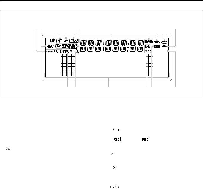
Display window
12 3 4 5 67 |
|
|
|
8 |
|
|
|
|
|
|
|
|
|
|
|
|
|
|
|
|
|
|
|
|
|
|
|
|
|
|
|
|
|
|
|
|
|
|
|
|
|
|
|
|
|
|
|
|
|
|
|
|
|
|
|
9 p q w |
||||||||||||||||||||||||||||||||||||||||||||||||||||||||||||||||||||||||||||||||
|
|
|
|
|
|
|
|
|
|
|
|
|
|
|
|
|
|
|
|
|
|
|
|
|
|
|
|
|
|
|
|
|
|
|
|
|
|
|
|
|
|
|
|
|
|
|
|
|
|
|
|
|
|
|
|
|
|
|
|
|
|
|
|
|
|
|
|
|
|
|
|
|
|
|
|
|
|
|
|
|
|
|
|
|
|
|
|
|
|
|
|
|
|
|
|
|
|
|
|
|
|
|
|
|
|
|
|
|
|
|
|
|
|
|
|
|
|
|
|
|
|
|
|
|
|
|
|
|
|
|
|
|
|
|
|
|
|
|
|
|
|
|
|
|
|
|
|
|
|
|
|
|
|
|
|
|
|
|
|
|
|
|
|
|
|
|
|
|
|
|
|
|
|
|
|
|
|
|
|
|
|
|
|
|
|
|
|
|
|
|
|
|
|
|
|
|
|
|
|
|
|
|
|
|
|
|
|
|
|
|
|
|
|
|
|
|
|
|
|
|
|
|
|
|
|
|
|
|
|
|
|
|
|
|
|
|
|
|
|
|
|
|
|
|
|
|
|
|
|
|
|
|
|
|
|
|
|
|
|
|
|
|
|
|
|
|
|
|
|
|
|
|
|
|
|
|
|
|
|
|
|
|
|
|
|
|
|
|
|
|
|
|
|
|
|
|
|
|
|
|
|
|
|
|
|
|
|
|
|
|
|
|
|
|
|
|
|
|
|
|
|
|
|
|
|
|
|
|
|
|
|
|
|
|
|
|
|
|
|
|
|
|
|
|
|
|
|
|
|
|
|
|
|
|
|
|
|
|
|
|
|
|
|
|
|
|
|
|
|
|
|
|
|
|
|
|
|
|
|
|
|
|
|
|
|
|
|
|
|
|
|
|
|
|
|
|
|
|
|
|
|
|
|
|
|
|
|
|
|
|
|
|
|
|
|
|
|
|
|
|
|
|
|
|
|
|
|
|
|
|
|
|
|
|
|
|
|
|
|
|
|
|
|
|
|
|
|
|
|
|
|
|
|
|
|
|
|
|
|
|
|
|
|
|
|
|
|
|
|
|
|
|
|
|
|
|
|
|
|
|
|
|
|
|
|
|
|
|
|
|
|
|
|
|
|
|
|
|
|
|
|
|
|
|
|
|
|
|
|
|
|
|
|
|
|
|
|
|
|
|
|
|
|
|
|
|
|
|
|
|
|
|
|
|
|
|
|
|
|
|
|
|
|
|
|
|
|
|
|
|
|
|
|
|
|
|
|
|
|
|
|
|
|
|
|
|
|
|
|
|
|
|
|
|
|
|
|
|
|
|
|
|
|
|
|
|
|
|
|
|
|
|
|
|
|
|
|
|
|
|
|
|
|
|
|
|
|
|
|
|
|
|
|
|
|
|
|
|
|
|
|
|
|
|
|
|
|
|
|
|
|
|
|
|
|
|
|
|
|
|
|
|
|
|
|
|
|
|
|
|
|
|
|
|
|
|
|
|
|
|
|
|
|
|
|
|
|
|
|
|
|
|
|
|
|
|
|
|
|
|
|
|
|
|
e r |
8 |
ty |
u |
See pages in parentheses for details.
Main unit |
Display window |
|
||||
1 Disc cover (12) |
1 |
Repeat indicators |
|
|||
2 ) OPEN (disc cover open) (12) |
|
• |
, ALL, GR. (group) |
|
||
3 DAILY TIMER/SNOOZE button (28) |
2 |
REC indicators |
|
|||
4 Remote sensor (5) |
|
• |
(recording), |
(recording timer) |
||
5 STANDBY lamp (10) |
3 |
MP3 indicator |
|
|||
6 |
|
(STANDBY/ON) button (10) |
4 |
ST. (stereo) indicator |
|
|
|
|
|||||
|
|
|||||
7 Source buttons |
5 |
|
(sleep timer) indicator |
|
||
|
• CD #¥8, TAPE ¤‹, FM/AM/DAB, AUX |
6 |
BASS indicator |
|
||
|
|
Pressing one of these buttons also turns on the unit. |
7 |
Timer indicators |
|
|
8 PHONES jack (10) |
|
• , 1, 2, 3, DAILY, WEEKLY |
||||
9 Multi control buttons |
8 |
Main display |
|
|||
|
• SCROLL DOWN 4, SELECT 7, SCROLL UP ¢ |
9 |
DAB indicator |
|
||
p Cassette holder (16, 25, 26) |
p RDS indicator |
|
||||
q Display window |
q |
|
(reverse mode) indicator |
|||
w VOLUME + / – control (10) |
w 2 3 (tape direction) indicator |
|||||
e AUX jack (8, 24) |
e PRGM (program) indicator |
|||||
r REC button (25, 26) |
r EQ. (equalizer) indicator |
|
||||
t PUSH OPEN (16, 25) |
t Frequency indicators |
|
||||
• kHz, MHz
y RND. (random) indicator u A.STANDBY indicator
4
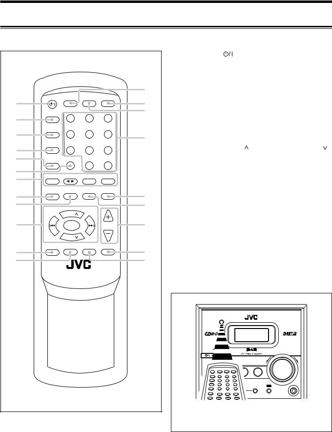
Remote Control
See pages in parentheses for details.
|
|
|
|
|
|
1 |
STANDBY/ON |
button (10, 28) |
|
||
|
|
|
|
|
|
2 |
SLEEP button (29) |
|
|
|
|
|
|
|
|
|
|
3 |
TIMER button (27) |
|
|
|
|
|
|
|
|
|
|
4 |
SET button (9, 27, 28) |
|
|
||
|
|
|
|
|
e |
5 |
CANCEL button (27, 28) |
|
|
||
|
|
|
|
|
6 |
REV. (reverse) MODE button (16, 25, 26) |
|
||||
|
|
|
|
|
|
|
|||||
1 |
STANDBY/ON |
CLOCK |
DISPLAY |
A. STANDBY |
r |
7 |
Source buttons |
|
|
|
|
|
|
|
|
|
|
|
|||||
|
|
|
|
|
• CD 3¥8, TAPE 2 3, FM/AM/DAB, AUX |
||||||
|
SLEEP |
|
|
|
t |
|
|||||
2 |
1 |
2 |
3 |
|
|
|
Pressing one of these buttons also turns on the unit. |
||||
|
|
|
|
||||||||
|
|
8 |
PROGRAM button (14, 18, 21) |
|
|
||||||
|
|
|
|
|
|
|
|
||||
3 |
TIMER |
|
|
|
|
9 |
RANDOM button (15) |
|
|
||
|
4 |
5 |
6 |
y |
|
|
|||||
|
p Multi control buttons |
|
|
||||||||
|
|
|
|
|
|
|
|||||
|
|
|
|
|
|
|
|
||||
4 |
SET |
|
|
|
|
|
• |
UP/PRESET GROUP , DOWN/PRESET GROUP |
|||
|
7 |
8 |
9 |
|
|
||||||
|
|
|
• |
SEARCH/SCROLL DOWN, SELECT, SEARCH/ |
|||||||
5 |
CANCEL |
REV. MODE |
|
|
|
|
|||||
|
|
|
|
|
SCROLL UP |
|
|
|
|||
|
|
|
0 |
+10 |
|
|
|
|
|
|
|
6 |
|
|
|
|
• 4, 7, ¢ |
|
|
|
|||
CD |
TAPE |
FM/AM/DAB |
AUX |
|
|
|
|
|
|||
7 |
|
q RDS/INFO button (17, 19, 20, 23) |
|
||||||||
3/8 |
|
|
|
|
|
||||||
|
|
|
REPEAT |
REMAIN |
|
w SCAN button (20) |
|
|
|
||
8 |
PROGRAM |
RANDOM |
/FM MODE |
/BEAT CUT |
u |
e CLOCK button (9) |
|
|
|
||
|
|
|
|
|
|
|
|||||
9 |
|
|
|
|
i |
r A. (auto) STANDBY button (10) |
|
|
|||
SCROLL |
PRESET |
SCROLL |
|
t DISPLAY button (15, 20, 23) |
|
|
|||||
|
SEARCH/ |
UP |
SEARCH/ |
|
|
|
|
|
|
|
|
|
DOWN |
GROUP |
UP |
|
|
y Number buttons (13, 14) |
|
|
|||
|
|
|
|
|
|
|
|||||
p |
|
|
|
|
o |
|
|
||||
|
7/ |
|
VOLUME |
u • |
REMAIN button (15) |
|
|
||||
|
SELECT |
|
|
|
|||||||
|
|
PRESET |
|
|
|
|
• |
BEAT CUT button (26) |
|
|
|
|
|
DOWN |
|
|
|
|
|
|
|
|
|
|
|
GROUP |
|
|
|
i • |
REPEAT button (15) |
|
|
||
|
|
|
|
|
|
|
|
||||
q |
RDS/INFO |
SCAN |
SOUND/HBS FADE MUTING |
; |
|
• |
FM MODE button (21) |
|
|
||
|
|
|
|
|
|
|
|||||
|
|
|
|
o VOLUME + / – buttons (10, 28) |
|
|
|||||
w |
|
|
|
|
a |
|
|
||||
|
|
|
|
; FADE MUTING button (11) |
|
|
|||||
|
|
|
|
|
|
|
|
||||
|
RM-SUXHB4 REMOTE CONTROL |
|
a SOUND/HBS button (11) |
|
|
||||||
|
|
|
|
|
|
|
|
STANDBY |
|
|
|
|
|
|
|
|
|
|
|
|
|
VOLUME |
|
|
|
|
|
|
|
|
|
|
|
– |
+ |
|
|
|
|
|
|
|
|
|
AUX |
|
|
|
|
|
|
|
|
|
|
|
SCROLL UP |
|
AUX |
|
|
|
|
|
|
|
|
|
¢ |
REC |
|
|
|
|
|
|
|
|
|
When using the remote control, point it at the |
|||
|
|
|
|
|
|
|
|
remote sensor on the front panel. |
|
||
5 |
|
|
|
|
|
|
|
|
|
|
|

Getting Started |
connections have been made. |
Continued |
|
Do not connect the AC power cord until all other |
|
|
|
|
|
|
|
Unpacking
After unpacking, check to be sure that you have all the following items.
The number in parentheses indicates the quantity of each piece supplied.
•DAB antenna (1)
•AM (MW) loop antenna (1)
•Remote control (1)
•Batteries (2)
•Antenna cover (1)
If any item is missing, consult your dealer immediately.
1Put the DAB antenna into the antenna cover until the DAB antenna fits in with the projection inside the antenna cover.
2Connect the DAB antenna to the DAB ANT. terminal.
To adjust the DAB antenna
Fix the antenna to pin up the wire with plastic eyelets vertically.
Connecting DAB Antenna
1 |
DAB anntenna (supplied) |
Antenna cover (supplied)
2
. ANT DAB
. ANT DAB
. ANT DAB
Eyelets 
If reception is poor
It is recommended to use the external antenna instead of supplied antenna.
6
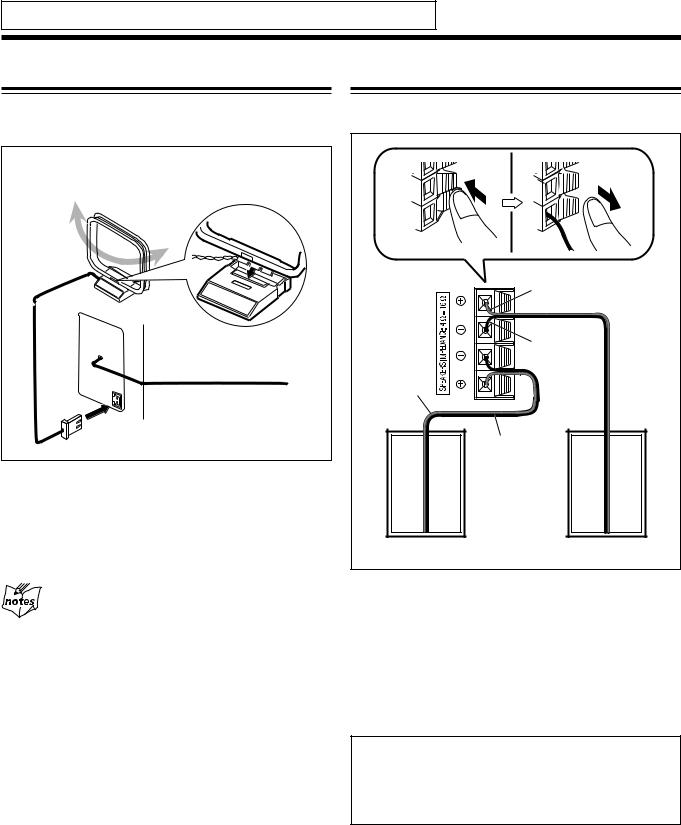
Do not connect the AC power cord until all other connections have been made.
Connecting AM (MW) and FM Antennas
Place the antenna away from the unit and adjust its position for the best reception.
1 AM (MW) loop antenna (supplied)
FM |
|
ANTENNA |
|
AM |
|
LOOP |
2 FM antenna |
|
1Adjust the position for the FM antenna for the best reception.
2Connect the supplied AM (MW) loop antenna to the AM LOOP terminal.
For better reception of both FM and AM (MW)
•Make sure the antenna conductors do not touch any other terminals or connecting cords.
•Keep the antennas away from metallic parts of the unit,
connecting cords, and the AC power cord.
Connecting Speakers
You can connect the speakers using the speaker cords.
1 |
2,3 |
|
Red |
Ò |
|
|
Black |
 |
|
Red |
|
Speaker |
Speaker |
cord |
cord |
|
Black |
Right speaker |
Left speaker |
1Hold the clamp of the speaker terminal.
2Insert the end of the speaker cord into the
terminal.
Match the polarity of the speaker terminals: red cord to ª and black cord to ·.
3 Release your finger from the clamp.
IMPORTANT:
•Use only speakers with the same speaker impedance as indicated by the speaker terminals on the rear of the unit.
•DO NOT connect more than one speaker to one speaker terminal.
7

Do not connect the AC power cord until all other connections have been made.
To remove the speaker grilles
The speaker grilles are removable as the illustration below.
Holes |
Projections |
Speaker grille
To remove the speaker grille, insert your fingers around the projection at the top of the speaker grille, then pull gently towards you while holding the side.
Do the same for the rest of projections one at a time.
To attach the speaker grille, put the projections of the speaker grille into the holes of the speaker.
Connecting Other Equipment
To connect an audio equipment
You can connect audio equipment—used only as a playback device.
• DO NOT connect any equipment while the power is on.
•DO NOT plug in any equipment until all connections are complete.
For playing other equipment through this unit, connect between the audio output jacks on the other equipment and AUX jack by using audio cords with mini plugs (not supplied).
To audio output |
|
|
L |
|
|
R |
|
|
OR |
To |
|
Audio equipment |
||
|
||
To audio output |
|
When the audio equipment has pin jacks for audio output: Be sure that the pin plugs of the audio cords are colored— white plugs and jacks are for left audio signals, and red ones for right audio signals.
Putting the Batteries into the Remote Control
Insert the batteries—AAA/UM-4/R03—into the remote control by matching the polarity (+ and –) on the batteries with the + and – marking on the battery compartment. When the remote control can no longer operate the unit, replace both batteries at the same time.
1
2
AAA/UM-4/R03
3
• DO NOT use an old battery together with a new one.
•DO NOT use different types of batteries together.
•DO NOT expose batteries to heat or flame.
•DO NOT leave the batteries in the battery compartment when you are not going to use the remote control for an extended period of time. Otherwise, the remote control will be damaged from battery leakage.
NOW you are ready to plug in the unit.
IMPORTANT:
Be sure to check that all connections have been made before plugging in the power cord.
8
 Loading...