


 Loading...
MICRO COMPONENT SYSTEM
UX-G5 —Consists of CA-UXG5 and SP-UXG5
INSTRUCTIONS
LVT1349-003A [UJ]
Warnings, Cautions and Others
CAUTION— (standby/on) button!
Disconnect the mains plug to shut the power off completely (all lamps and indications go off). The  button in any position does not disconnect the mains line.
•When the unit is on standby, the STANDBY lamp lights in red.
•When the unit is turned on, the STANDBY lamp goes off.
The power can be remote controlled.
CAUTION
To reduce the risk of electrical shocks, fire, etc.:
1.Do not remove screws, covers or cabinet.
2.Do not expose this appliance to rain or moisture.
CAUTION
•Do not block the ventilation openings or holes.
(If the ventilation openings or holes are blocked by a newspaper or cloth, etc., the heat may not be able to get out.)
•Do not place any naked flame sources, such as lighted candles, on the apparatus.
•When discarding batteries, environmental problems must be considered and local rules or laws governing the disposal of these batteries must be followed strictly.
•Do not expose this apparatus to rain, moisture, dripping or splashing and that no objects filled with liquids, such as vases, shall be placed on the apparatus.
IMPORTANT FOR LASER PRODUCTS
1.CLASS 1 LASER PRODUCT
2.CAUTION: Do not open the top cover. There are no user serviceable parts inside the Unit; leave all servicing to qualified service personnel.
3.CAUTION: Visible and invisible laser radiation when open and interlock failed or defeated. Avoid direct exposure to beam.
4.REPRODUCTION OF LABEL: CAUTION LABEL, PLACED INSIDE UNIT.
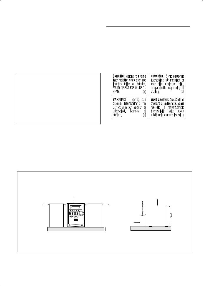
Caution: Proper Ventilation
To avoid risk of electric shock and fire, and to prevent damage, locate the apparatus as follows:
1. |
Front: |
No obstructions and open spacing. |
2. |
Sides/ Top/ Back: No obstructions should be placed in the areas shown by the dimensions below. |
|
3. |
Bottom: |
Place on the level surface. Maintain an adequate air path for ventilation by placing on a stand with a height |
|
|
of 10 cm or more. |
Front |
|
15 cm |
|
Side |
15 cm |
1 cm |
|
1 cm |
|||
15 cm |
|
15 cm |
|
||
|
|
|
|
|
15 cm |
|
|
|
|
10 cm |
|
|
SP-UXG5 |
CA-UXG5 |
SP-UXG5 |
|
CA-UXG5 |
About the cooling fan
A cooling fan is mounted on the rear panel of the unit to prevent abnormal temperature inside the unit, thus assuring normal operation of the unit. The cooling fan automatically starts rotating to intake external cool air when the volume is increased up to more than a certain level.
G-1

Contents |
|
Introduction ..................................................... |
2 |
Precautions...................................................................... |
2 |
How to Read This Manual.............................................. |
2 |
Getting Started ................................................ |
3 |
Step 1: Unpack................................................................ |
3 |
Step 2: Prepare the Remote Control ............................... |
3 |
Step 3: Hook Up ............................................................. |
4 |
Before Operating the System ......................... |
7 |
Daily Operations—Playback .......................... |
8 |
Listening to the Radio..................................................... |
9 |
Playing Back a Disc...................................................... |
10 |
Playing Back a Tape ..................................................... |
12 |
Playing Back Other Equipment .................................... |
12 |
Daily Operations |
|
—Sound & Other Adjustments ................ |
13 |
Adjusting the Volume................................................... |
13 |
Adjusting the Sound ..................................................... |
13 |
Changing the Display Brightness—DIMMER............. |
14 |
Setting the Clock .......................................................... |
14 |
Turning Off the Power Automatically.......................... |
14 |
Advanced Disc Operations ........................... |
15 |
Programming the Playing Order—Program Play ......... |
15 |
Playing at Random—Random Play.............................. |
16 |
Playing Repeatedly—Repeat Play................................ |
17 |
Prohibiting Disc Ejection—Child Lock ....................... |
17 |
Advanced Tape Operations .......................... |
18 |
Recording on a Tape..................................................... |
18 |
Synchronized Disc Recording ...................................... |
19 |
Timer Operations .......................................... |
20 |
Setting the Timer .......................................................... |
20 |
Additional Information ................................ |
22 |
Learning More about This System ............................... |
22 |
Troubleshooting............................................................ |
24 |
Maintenance.................................................................. |
25 |
Specifications................................................................ |
25 |
Parts Index .................................................................... |
26 |
1
Introduction
Precautions
Installation
•Install in a place which is level, dry and neither too hot nor too cold—between 5°C and 35°C.
•Install the System in a location with adequate ventilation to prevent internal heat buildup inside the System.
DO NOT install the System in a location near heat sources, or in a place subject to direct sunlight, excessive dust or vibration.
•Leave sufficient distance between the System and the TV.
•Keep the speakers away from the TV to avoid interference with TV.
Power sources
•When unplugging the System from the wall outlet, always pull on the plug, not the AC power cord.
DO NOT handle the AC power cord with wet hands.
Moisture condensation
Moisture may condense on the lenses inside the System in the following cases:
•After starting to heat the room
•In a damp room
•If the System is brought directly from a cold to a warm place
Should this occur, the System may malfunction. In this case, leave the System turned on for a few hours until the moisture evaporates, unplug the AC power cord, then plug it in again.
Internal heat
•A cooling fan is mounted on the rear panel to prevent heat buildup inside the main unit (see page G-1).
For safety, observe the following carefully:
•Make sure there is good ventilation around the main unit. Poor ventilation could overheat and damage the System.
• DO NOT block the cooling fan and the ventilation openings or holes. If they are blocked by a newspaper or cloth, etc., the heat may not be able to get out.
Others
•Should any metallic object or liquid fall into the System, unplug the AC power cord and consult your dealer before operating any further.
DO NOT disassemble the System since there are no user serviceable parts inside.
2
•If you are not going to operate the System for an extended period of time, unplug the AC power cord from the wall outlet.
If anything goes wrong, unplug the AC power cord and consult your dealer.
How to Read This Manual
To make this manual as simple and easy-to-understand as possible, we have adapted the following methods:
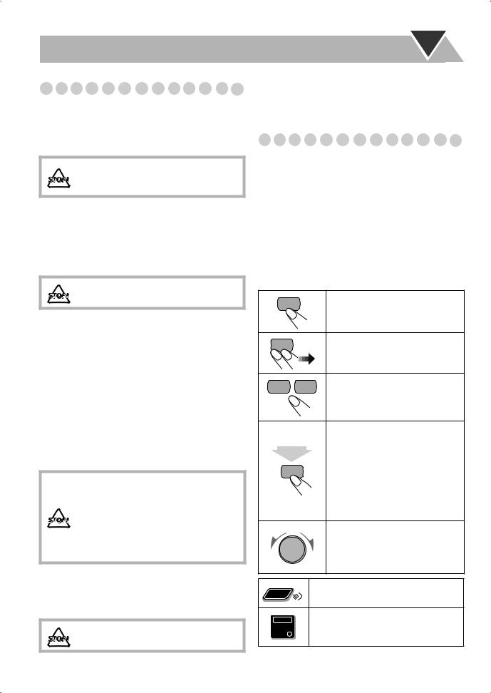
•Button and control operations are explained as listed in the table below. In this manual, the operations using the remote control is mainly explained; however, you can use the buttons and controls on the main unit if they have the same (or similar) name and marks.
•Some related tips and notes are explained later in the sections “Learning More about This System” and “Troubleshooting,” but not in the same section explaining the operations. If you want to know more about the functions, or if you have a doubt about the functions, go to these sections and you will find the answers.
Indicates that you press the button briefly.
Indicates that you press the button briefly and repeatedly until an option you want is selected.
Indicates that you press one of the buttons.
Indicates that you press and hold the button for specified seconds.
2 • The number inside the arrow sec.
indicates the period of press (in this example, 2 seconds).
•If no number is inside the arrow, press and hold until the entire procedure is complete or until you get a result you want.
Indicates that you turn the control toward the specified direction(s).
Remote |
Indicates that this operation is only possible |
|
using the remote control. |
||
ONLY |
Indicates that this operation is only possible
Main Unit using the buttons and controls on the main
ONLY
unit.

Getting Started
Step 1:Unpack the package and check the accessories.
Step 2: Prepare the remote control.
Step 3: Hook up the components such as AM/FM antennas, speakers, etc. (see pages 4 to 6).
|
AM |
ANTENNA |
AM |
EXT |
|
|
|
|
LOOP |
|
|
|
GND |
|
Finally plug the AC power cord.
Now you can operate the System.
Step 1: Unpack
After unpacking, check to be sure that you have all the following items. The number in parentheses indicates the quantity of each piece supplied.
•FM antenna (1)
•AM loop antenna (1)
•Remote control (1)
•Batteries (2)
•AC plug adapter (1)
If any item is missing, consult your dealer immediately.
Step 2: Prepare the Remote Control
Insert the batteries into the remote control by matching the polarity (+ and –) correctly.
1
R6(SUM-3)/AA(15F)
3
• DO NOT use an old battery together with a new one.
•DO NOT use different types of batteries together.
•DO NOT expose batteries to heat or flame.
•DO NOT leave the batteries in the battery compartment when you are not going to use the remote control for an extended period of time. Otherwise, the remote control will be damaged from battery leakage.
3
Step 3: Hook Up
If you need more detailed information, see page 6.
Illustrations of the input/output terminals below are typical examples.
When you connect other components, refer also to their manuals since the terminal names actually printed on the rear may vary.
Turn the power off to all components before connections.
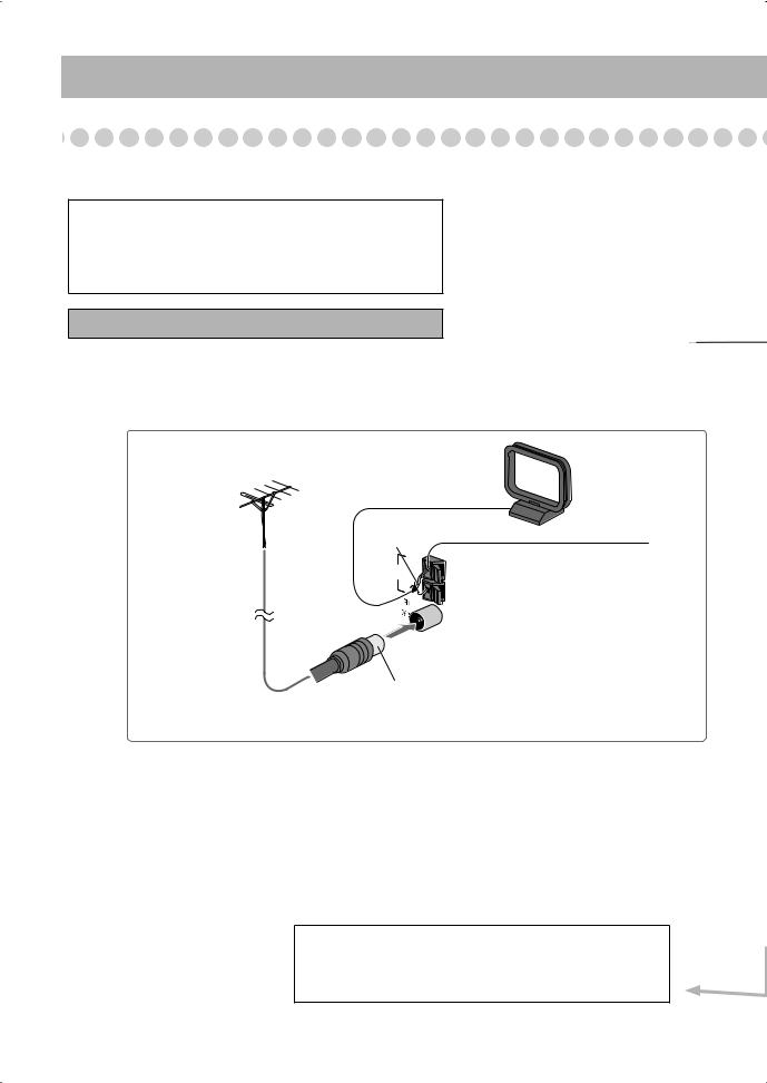
For better FM/AM reception
Outdoor FM |
White |
|
ANTENNA |
|
|
||
antenna |
|
AM |
|
(not supplied) |
AM |
EXT |
|
|
|
||
LOOP |
|
|
|
|
|
|
|
|
|
GND |
|
AM loop antenna
Keep it connected.
Vynile-covered wire (not supplied)
Extend it horizontally.
Disconnect the supplied FM antenna, and connect to an outdoor FM antenna using a 75 Ω wire with coaxial type connector.
To a wall outlet
Plug the AC power cord only after all connections are complete.
• If the wall outlet does not match the AC plug, use the supplied AC plug adapter.
4
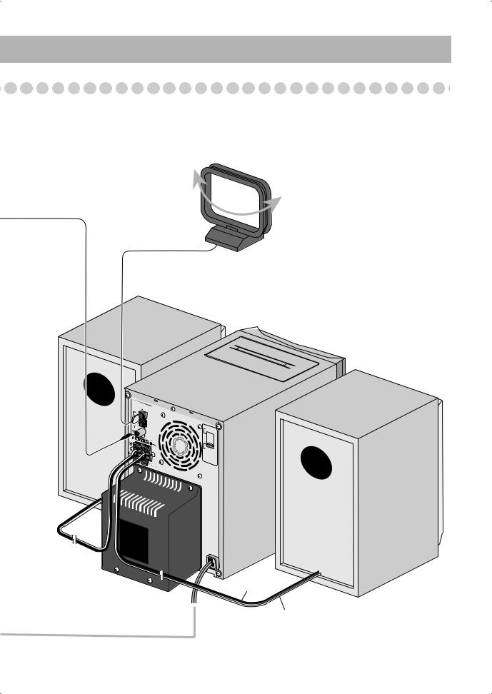
FM antenna (supplied) |
|
Extend it so that |
|
you can obtain |
|
the best |
|
reception. |
AM loop antenna (supplied) |
|
|
|
Turn it until the best reception is |
|
obtained. |
AM LOOP
AM  EXT
EXT

GND
110V– |
127V |
|
|
||
220V– |
240V |
|
AC |
||
|
||
VOLTAGE |
||
SELECTOR |
||
Black stripe
Non-stripe
5
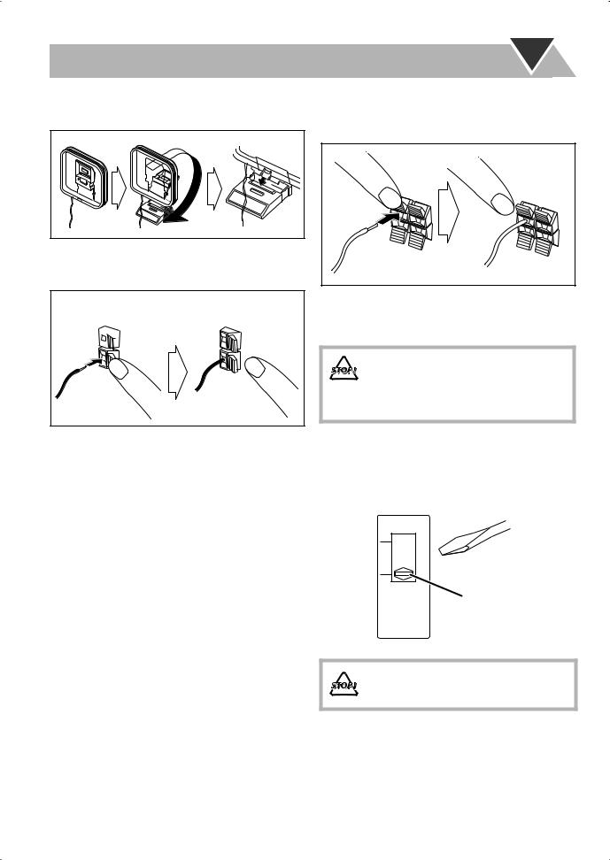
To assemble and connect the AM loop antenna
To assemble the AM loop antenna
To connect the AM loop antenna
Make sure to connect the wire correctly: The white end to AM EXT, the black end to GND.
 1 Hold
2 Insert |
3 Release |
•If the AM loop antenna wire or speaker cords are covered with vinyl, remove the vinyl to expose the tip of the antenna by twisting the vinyl.
•Make sure the antenna conductors do not touch any other terminals, connecting cords and power cord. Also, keep the antennas away from metallic parts of the System, connecting cords, and the AC power cord. This could cause poor reception.
To connect the speaker cords
Make sure the both speakers are connected correctly and firmly.
3 Release
1 Hold
2 Insert
When connecting the speaker cords, match the polarity of the speaker terminals: The cord with black stripe to (–), the cord without stripe to (+).
• DO NOT connect more than one speaker to each terminal.
•DO NOT allow the conductor of the speaker cords to be in touch with the metallic parts of the System.
Adjusting the voltage selector
Use a screwdriver to slide the voltage selector so that the voltage marker is pointing at the same voltage as where you are plugging in the unit. (See also the back cover page.)
 110V-127V
 220V-240V
Voltage marker
AC VOLTAGE
SELECTOR
DO NOT plug in before setting the voltage selector on the rear of the unit and all connection procedures are complete.
6
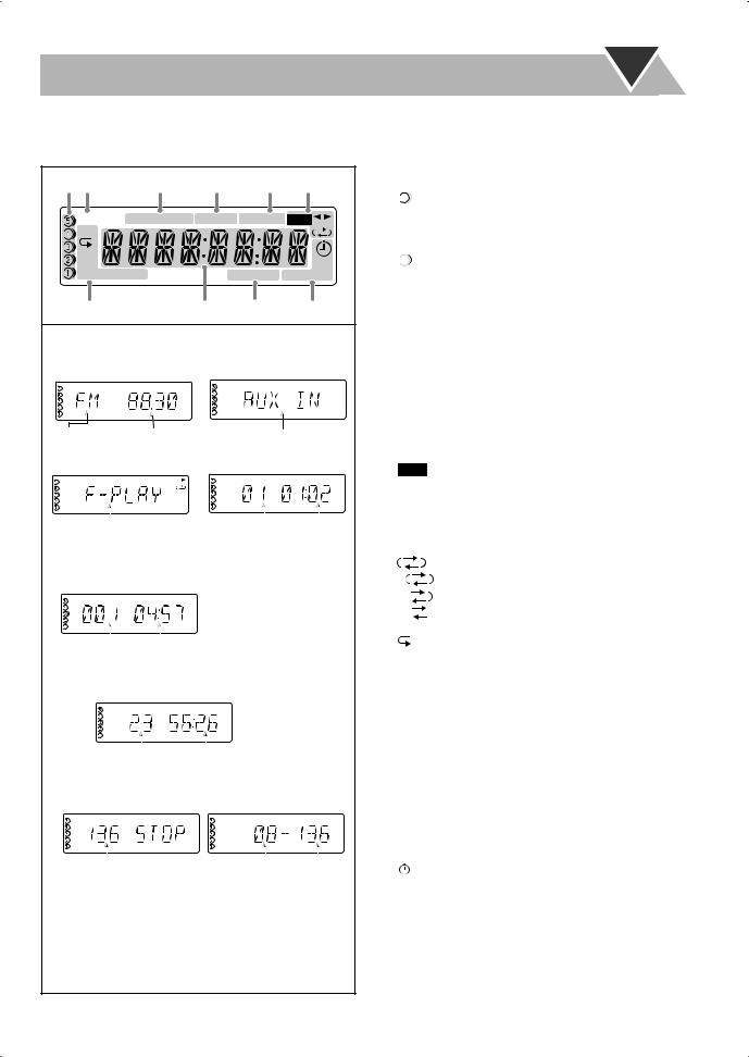
Before Operating the System
The indications on the display teach you a lot of things while you are operating the System.
Before operating the System, be familiar with when and how the indicator illuminates on the display.
|
|
|
|
|
1 Disc tray indicators |
||
1 2 |
3 |
4 |
5 |
6 |
• 1–5: Disc tray number |
||
|
|
|
|
|
• |
: Tray indicator |
|
MP3 |
SOUND TURBO AHB PRO MONO ST |
REC |
|
– Lights when the disc is detected. |
|||
|
– Blinking while playing back a disc. |
||||||
GR. |
|
|
|
|
|
||
1CD |
|
|
|
|
|
– Goes off when there is no disc in the tray. |
|
|
|
|
REC |
• |
: Shows the current disc. |
||
ALL |
|
|
|
||||
PRGM RANDOM |
|
A.STANDBY SLEEP 123 |
2 MP3 indicator |
||||
|
|
|
|
|
• Lights when an MP3 disc is detected. |
||
7 |
|
8 |
9 |
p |
3 SOUND TURBO indicator |
||
|
|
|
|
|
• Lights when the SOUND TURBO is activated (see |
||
Indications on the main display |
|
|
|
page 13). |
|||
• While listening to radio: |
• While selecting AUX: |
4 AHB PRO (Active Hyper Bass Pro) indicator |
|||||
• Lights when the AHB PRO is activated. |
|||||||
|
|
|
|
|
|||
|
ST REC |
|
|
REC |
5 FM reception indicators |
||
|
|
|
|
• MONO: Lights while the FM monaural mode is |
|||
|
|
|
|
|
|||
|
|
|
|
|
|
activated. |
|
Band |
Frequency |
|
Source name |
• ST (stereo): Lights while an FM stereo station with |
|||
|
|
sufficient signal strength is tuned in. |
|||||
|
|
|
|
|
|
||
• While playing a TAPE: |
• While playing a CD: |
6 Tape operation indicators |
|||||
• |
REC indicator |
||||||
|
|
|
|
|
|||
|
|
|
|
|
|
|
|
|
REC |
|
|
|
|
|
|
|
|
|
REC |
– Lights while recording. |
|||||||
|
|
|
|
|
|
|
|
|
|
|
|
|
|
|
|
|
|
|
|
|
|
||||||
|
|
|
|
|
|
|
|
|
|
|
|
|
|
|
|
|
|
|
|
|
|
• 2 3 (tape direction): |
|||||
|
|
|
|
|
direction *1 |
|
|
|
|
|
|
|
|
|
|
|
|
– Lights to indicate the current tape running direction. |
|||||||||
|
|
|
Tape |
|
|
|
Track |
Elapsed playing |
– Flashes slowly during playback and recording. |
||||||||||||||||||
|
|
|
|
|
|
|
|
|
|
|
|
|
number |
time |
|||||||||||||
|
|
|
|
|
|
|
|
|
|
|
|
|
– Flashes quickly while rewinding a tape. |
||||||||||||||
|
|
|
|
|
|
|
|
|
|
|
|
|
|
|
|
|
|
|
|
|
|
||||||
• While playing an MP3*2: |
|
|
|
|
|
• |
|
(Reverse mode): |
|||||||||||||||||||
|
|
|
|
|
– |
|
|
|
: Tape play continues endlessly. |
||||||||||||||||||
|
|
|
|
|
|
|
|
|
|
|
|
|
|
|
|
|
|
|
|
|
|
|
|
|
|||
|
MP3 |
REC |
|
|
|
|
|
|
|
|
|
|
|
– |
|
|
|
: Tape automatically reverses once. |
|||||||||
|
|
|
|
|
|
|
|
|
|
|
|
|
|
|
|||||||||||||
|
|
|
|
|
|
|
|
|
|
|
|
– |
|
|
|
: Tape play stops at the end of one side. |
|||||||||||
|
|
|
|
|
|
|
|
|
|
|
|
|
|
|
|
|
|
|
|
|
|
|
|
|
|||
|
|
|
|
|
|
|
|
|
|
|
|
|
|
|
|
|
|
|
|
|
|
7 Disc |
|
|
|||
|
|
|
|
|
|
|
|
|
|
|
|
|
|
|
|
|
|
|
|
|
|
operation mode indicators |
|||||
|
|
|
|
|
|
|
|
|
|
|
|
|
|
|
|
|
|
|
|
|
|
||||||
Current track number |
|
Elapsed playing time |
• |
|
: Lights when Repeat mode is activated. |
||||||||||||||||||||||
|
– GR.: Repeats all the tracks in the selected group. |
||||||||||||||||||||||||||
|
|
|
|
|
|
|
|
|
|
|
|
|
|
|
|
|
|
|
|
|
|
||||||
• While disc play is stopped: |
|
|
|
|
|
– 1: Repeats the track. |
|||||||||||||||||||||
CD: |
|
|
|
|
|
|
|
|
|
|
|
|
– CD: Repeats the disc. |
||||||||||||||
|
|
|
|
|
|
|
|
|
|
|
|
|
|
REC |
|
|
|
|
|
– ALL: Repeats all the discs. |
|||||||
|
|
|
|
|
|
|
|
|
|
|
|
|
|
|
|
|
|
|
|
|
|
• PRGM (program): Lights when Program Play mode is |
|||||
|
|
|
|
|
|
|
|
|
|
|
|
|
|
|
|
|
|
|
|
|
|
activated. |
|||||
|
|
|
|
|
|
|
|
|
|
|
|
|
|
|
|
|
|
|
|
|
|
||||||
|
|
|
|
|
|
|
|
|
|
|
|
|
|
|
|
|
|
|
|
|
|
• RANDOM: Lights when Random Play mode is |
|||||
|
|
|
Total track number |
|
|
Total playing time |
|||||||||||||||||||||
|
|
|
|
|
activated. |
||||||||||||||||||||||
|
|
|
|
|
|
|
|
|
|
|
|
|
|
|
|
|
|
|
|
|
|
||||||
MP3: |
|
|
|
|
|
|
|
|
|
|
|
|
8 Main display |
||||||||||||||
|
|
|
|
|
|
|
|
|
|
|
|
9 A(auto). STANDBY indicator |
|||||||||||||||
• While in “TRACK” mode: |
|
|
|
• While in “GROUP” mode: |
|||||||||||||||||||||||
|
|
|
• Lights when Auto Standby is activated. |
||||||||||||||||||||||||
|
|
|
|
|
|
|
|
|
|
|
|
|
|
|
|
|
|
|
|
|
|
||||||
|
MP3 |
REC |
|
|
|
MP3 |
|
|
REC |
• Flashes when disc playback stops with Auto Standby |
|||||||||||||||||
|
|
|
|
|
|
|
|
|
|
|
|
|
|
GR. |
|
|
|
|
|
||||||||
|
|
|
|
|
|
|
|
|
|
|
|
|
|
|
|
|
|
|
|
|
|
activated. |
|||||
|
|
|
|
|
|
|
|
|
|
|
|
|
|
|
|
|
|
|
|
|
|
p Timer indicators |
|||||
|
Total track number |
|
|
|
|
Total group Total track |
• |
|
: Lights when Daily Timer or Recording Timer stands |
||||||||||||||||||
|
|
|
|
|
|
|
|
|
|
|
|
|
|
number |
|
number |
|
||||||||||
|
|
|
|
|
|
|
|
|
|
|
|
|
|
|
by; flashes while working. |
||||||||||||
|
|
|
|
|
|
|
|
|
|
|
|
|
|
|
|
|
|
|
|
|
|
||||||
*1 |
While playing back a tape, “F-PLAY (Forward play)” |
• 1/2/3: Lights when a Daily Timer (1, 2, or 3) stands by; |
|||||||||||||||||||||||||
flashes while setting or working. |
|||||||||||||||||||||||||||
|
or “R-PLAY (Reverse play)” appears on the display. |
||||||||||||||||||||||||||
|
• REC: Lights when the Recording Timer stands by; |
||||||||||||||||||||||||||
*2 |
When you start playing an MP3 disc, the group |
||||||||||||||||||||||||||
flashes while setting or working. |
|||||||||||||||||||||||||||
|
number, track number, track name, (and ID3 Tag) will |
• SLEEP: Lights when the Sleep Timer is activated. |
|||||||||||||||||||||||||
|
be shown before the elapsed playing time appears. |
|
|
|
|
|
|||||||||||||||||||||
7
Loading...