


UX-GB9DAB
MICRO COMPONENT SYSTEM
UX-GB9DAB
—Consists of CA-UXGB9DAB and SP-UXGB9DAB
INSTRUCTIONS
GVT0172-001A
[B]
Warnings, Cautions and Others
IMPORTANT for the U.K.
DO NOT
plug fitted is not suitable for the power points in your home
or the cable is too short to reach a power point, then obtain
an appropriate safety approved extension lead or consult
your dealer.
BE SURE
approved type, as originally fitted.
If nonetheless the mains plug is cut off ensure to remove the
fuse and dispose of the plug immediately, to avoid a possible
shock hazard by inadvertent connection to the mains supply.
If this product is not supplied fitted with a mains plug then
follow the instructions given below:
IMPORTANT:
DO NOT
marked with the letter E or by the safety earth symbol or
coloured green or green-and-yellow.
The wires in the mains lead on this product are coloured in
accordance with the following code:
As these colours may not correspond with the coloured
markings identifying the terminals in your plug proceed as
follows:
The wire which is coloured blue must be connected to the
terminal which is marked with the letter N or coloured black.
The wire which is coloured brown must be connected to the
terminal which is marked with the letter L or coloured red.
IF IN DOUBT - CONSULT A COMPETENT ELECTRICIAN.
CAUTION— button!
Disconnect the mains plug to shut the power off completely (the
STANDBY lamp goes off). When installing the apparatus,
ensure that the plug is easily accessible. The button in any
position does not disconnect the mains line.
• When the unit is on standby, the STANDBY lamp lights red.
• When the unit is turned on, the STANDBY lamp goes off.
The power can be remote controlled.
CAUTION
To reduce the risk of electrical shocks, fire, etc.:
1. Do not remove screws, covers or cabinet.
2. Do not expose this appliance to rain or moisture.
cut off the mains plug from this equipment. If the
to replace the fuse only with an identical
make any connection to the terminal which is
Blue: Neutral
Brown: Live
IMPORTANT FOR LASER PRODUCTS
1. CLASS 1 LASER PRODUCT
2.
CAUTION:
serviceable parts inside the unit; leave all servicing to
qualified service personnel.
3.
CAUTION:
when open. Do not view directly with optical instruments.
4. REPRODUCTION OF LABEL: CAUTION LABEL, PLACED
INSIDE THE UNIT.
CAUTION
• Do not block the ventilation openings or holes.
(If the ventilation openings or holes are blocked by a
newspaper or cloth, etc., the heat may not be able to get
out.)
• Do not place any naked flame sources, such as lighted
candles, on the apparatus.
• When discarding batteries, environmental problems must
be considered and local rules or laws governing the
disposal of these batteries must be followed strictly.
• Do not expose this apparatus to rain, moisture, dripping or
splashing and that no objects filled with liquids, such as
vases, shall be placed on the apparatus.
Dear Customer,
This apparatus is in conformance with the valid European
directives and standards regarding electromagnetic
compatibility and electrical safety.
European representative of Victor Company of Japan
Limited is:
JVC Technology Centre Europe GmbH
P.O. Box 10 05 52
61145 Friedberg
Germany
Do not open the top cover. There are no user
Visible and/or invisible class 1M laser radiation
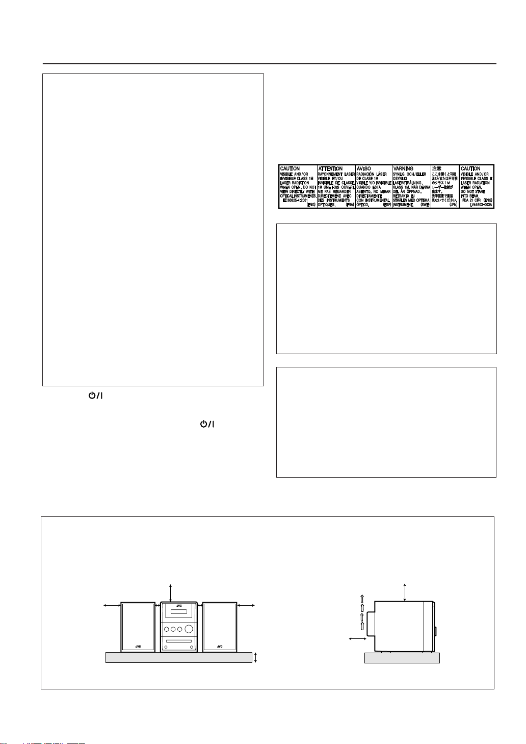
Caution: Proper Ventilation
To avoid risk of electric shock and fire, and to prevent damage, locate the apparatus as follows:
1. Front: No obstructions and open spacing.
2. Sides/Top/Back: No obstructions should be placed in the areas shown by the dimensions below.
3. Bottom: Place on the level surface. Maintain an adequate air path for ventilation by placing on a stand with a height of 10 cm
or more.
Front view Side view
15 cm
SP-UXGB9DAB
15 cm
1 cm
CA-UXGB9DAB
1 cm
SP-UXGB9DAB
15 cm
10 cm
15 cm
15 cm
CA-UXGB9DAB
G-1

Information for Users on Disposal of Old Equipment
[European Union]
This symbol indicates that the electrical and electronic equipment should not be disposed
as general household waste at its end-of-life. Instead, the product should be handed over
to the applicable collection point for the recycling of electrical and electronic equipment for
proper treatment, recovery and recycling in accordance with your national legislation.
By disposing of this product correctly, you will help to conserve natural resources and will
help prevent potential negative effects on the environment and human health which could
otherwise be caused by inappropriate waste handling of this product. For more information
about collection point and recycling of this product, please contact your local municipal
office, your household waste disposal service or the shop where you purchased the product.
Attention:
This symbol is only
valid in the
European Union.
Penalties may be applicable for incorrect disposal of this waste, in accordance with national
legislation.
(Business users)
If you wish to dispose of this product, please visit our web page www.jvc-europe.com
obtain information about the take-back of the product.
[Other Countries outside the European Union]
If you wish to dispose of this product, please do so in accordance with applicable national
legislation or other rules in your country for the treatment of old electrical and electronic
equipment.
to
G-2

Introduction
Remote
ONLY
Main Unit
ONLY
Precautions
Installation
• Install in a place which is level, dry and neither too hot nor
too cold—between 5°C and 35°C.
• Install the System in a location with adequate ventilation to
prevent internal heat buildup inside the System.
DO NOT install the System in a location near
heat sources, or in a place subject to direct
sunlight, excessive dust or vibration.
• Leave sufficient distance between the System and the TV.
• Keep the speakers away from the TV to avoid interference
with the TV.
Power sources
• When unplugging the System from the wall outlet, always
pull on the plug, not the AC power cord.
DO NOT handle the AC power cord with wet
hands.
Moisture condensation
Moisture may condense on the lenses inside the System in
the following cases:
• After starting to heat the room
• In a damp room
• If the System is brought directly from a cold to a warm
place
Should this occur, the System may malfunction. In this case,
leave the System turned on for a few hours until the moisture
evaporates, unplug the AC power cord, then plug it in again.
How to Read This Manual
• Button and control operations are explained in the table
below.
•
Some related tips and notes are explained later in the
sections “Learning More about This System” and
“Troubleshooting,” but not in the same section
explaining the operations
content has some information).
2 sec.
( indicates that the
Indicates that you press the button
.
briefly
Indicates that you press the button
briefly and repeatedly
option you want is selected.
Indicates that you press one of the
buttons.
Indicates that you
button for specified seconds.
• The number inside the arrow
indicates the period of press (in this
example, 2 seconds).
• If no number is inside the arrow,
press and hold until the entire
procedure is complete or until you
get a result you want.
Indicates that you turn the control
toward the specified direction(s).
until an
press and hold
the
Others
• Should any metallic object or liquid fall into the System,
unplug the AC power cord and consult your dealer before
operating any further.
DO NOT disassemble the System since there
are no user serviceable parts inside.
• If you are not going to operate the System for an extended
period of time, unplug the AC power cord from the wall
outlet.
If anything goes wrong, unplug the AC power cord and
consult your dealer.
1
Indicates that this operation is only
possible using the remote control.
Indicates that this operation is only
possible using the buttons and controls on
the main unit.

Contents
Introduction ............................................................... 1
Connections ................................................................ 3
Before Operating the System.................................... 6
Daily Operations—Playback .................................... 7
Listening to the Radio ..................................................................8
Playing Back a Disc .....................................................................8
Playing Back a Portable Audio Device........................................ 9
Daily Operations—Sound&Other Adjustments... 10
Adjusting the Volume ................................................................10
Adjusting the Sound................................................................... 10
Changing the Display Brightness............................................... 11
Adjusting the Audio Input Level ............................................... 11
Setting the Clock........................................................................ 11
Turning Off the Power Automatically .......................................11
Radio Data System Operations .............................. 12
Changing the Display Mode ...................................................... 12
Searching for a Program by PTY Codes.................................... 12
Switching Temporarily to a Program of Your Choice
Automatically ......................................................................... 13
Description of the PTY codes for Radio Data System............... 13
DAB Operations....................................................... 14
Listening to a Service................................................................. 14
Presetting Services .....................................................................15
Changing the Display Mode ...................................................... 16
Searching for a Service by PTY Codes...................................... 16
Switching Temporarily to a Service of Your Choice
Automatically ......................................................................... 17
Description of the PTY codes for DAB ..................................... 17
Advanced Disc Operations...................................... 18
Programming the Playing Order—Program Play ......................18
Playing at Random—Random Play ...........................................19
Playing Repeatedly—Repeat Play .............................................19
Prohibiting Disc Ejection—Child Lock..................................... 19
Timer Operations .................................................... 20
Setting the Timer........................................................................ 20
Timer Priority............................................................................. 21
Additional Information ........................................... 22
Learning More about This System............................................. 22
Troubleshooting .........................................................................23
Maintenance ............................................................................... 23
Specifications ............................................................................. 24
Parts Index.................................................................................. 24
2
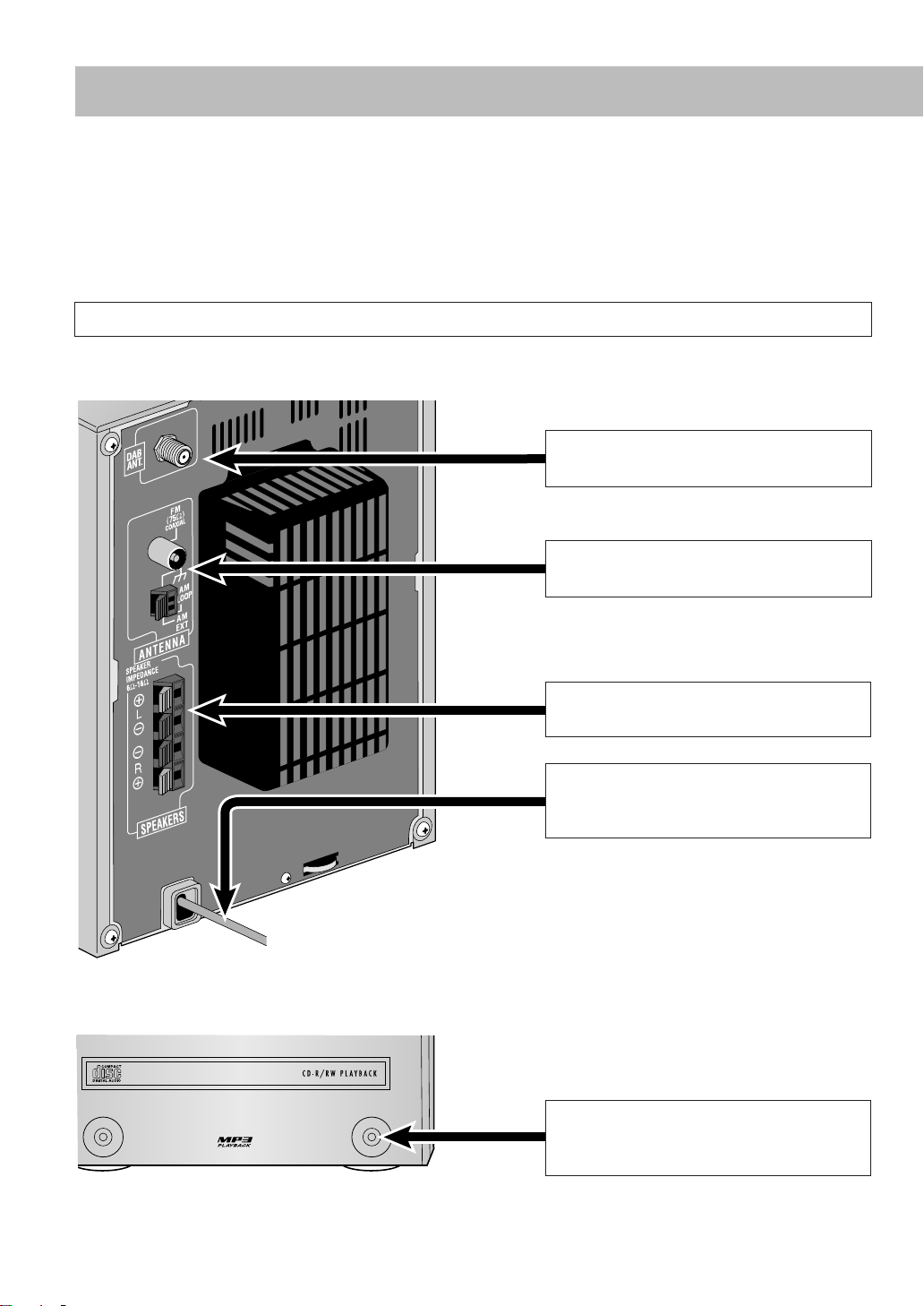
Connections
PHONES
AUX
Supplied accessories
After unpacking, check to be sure that you have all the following items:
• DAB antenna (1)
• FM antenna (1)
• AM loop antenna (1)
If any item is missing, consult your dealer immediately.
Do not connect the AC power cord until all other connections have been made.
Rear view
• Remote control (1)
• Batteries (2)
11
11
From DAB antenna
See page 4.
22
22
From AM/FM antenna
See page 4.
Front view
33
33
From the speakers
See page 5.
44
44
To a wall outlet
Plug in the AC power cord only after all
connections are complete.
From the analog audio output of portable
audio devices
See page 5.
3
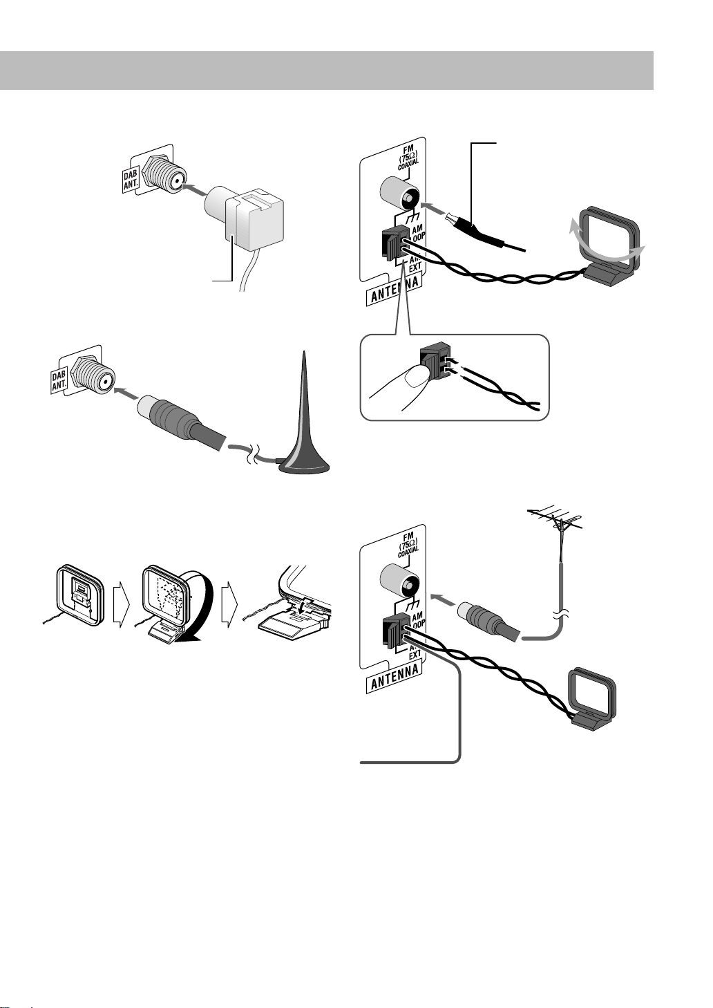
11
11
DAB antenna
DAB antenna (supplied)
Extend the wire so that you can
receive your desired ensembles.
For the better DAB reception
Active antenna
(not supplied)
• See also “To improve DAB reception” on page 15.
To connect the AM loop antenna
FM antenna (supplied)
Extend it so that you can
obtain the best reception.
AM loop antenna (supplied)
Turn it until the best reception is
obtained.
• If the AM loop antenna wire is covered with vinyl, remove
the vinyl to expose the tip of the antenna by twisting the
vinyl.
For the better AM/FM reception
22
AM/FM antenna
22
To assemble the AM loop antenna
Outdoor FM antenna
(not supplied)
AM loop antenna (supplied)
Keep it connected.
Vinyl-covered wire (not supplied)
Extend it horizontally.
• Disconnect the supplied FM antenna, and connect to an
outdoor FM antenna using a 75 Ω wire with coaxial type
connector (IEC or DIN45325).
• Make sure the antenna conductors do not touch any other
terminals, connecting cords, or the power cord. Also, keep
the antennas away from metallic parts of the System,
connecting cords, and the AC power cord. This could cause
poor reception.
4
33
DOWN
UP
PHONES
AUX
Speakers
33
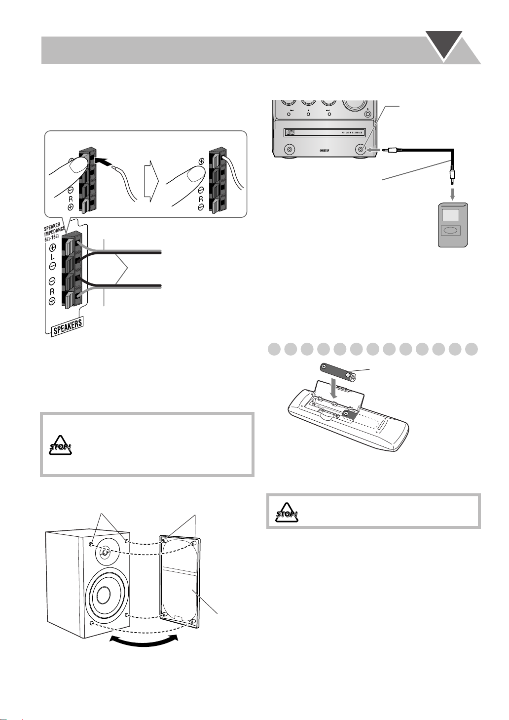
To connect the speaker cords
Make sure that both speakers are connected correctly and
firmly.
1 Hold 2 Insert 3 Release
To connect a portable audio device
AUX jack
Stereo mini plug cord
(not supplied)
Red
From left speaker
Black
From right speaker
Red
• When connecting the speaker cords, match the polarity of
the speaker terminals: red cord to (+) and black cord to (–).
• If the speaker cords are covered with vinyl, remove the
vinyl to expose the tip of the speaker cord by twisting the
vinyl.
• DO NOT connect more than one speaker to
each terminal.
• DO NOT allow the conductor of the speaker
cords to be in touch with the metallic parts of
the System.
To remove the speaker grilles:
Holes Projections
Portable audio device
• By using QP Link (Quick Portable Link), you can easily
start playing back a portable audio device on this unit. See
page 9 for details.
• If an external device is not equipped with a stereo mini plug
audio output, use a plug adapter to convert the stereo mini
plug to the corresponding plug of the audio output.
Preparing the remote control
R03(UM-4)/AAA(24F)
• Dispose of batteries in the proper manner, according to
federal, state, and local regulations.
DO NOT recharge, short, disassemble, heat
the battery or dispose of it in a fire.
When using the remote control
Point the top of the remote control toward the remote sensor
as directly as possible. If you operate it from a diagonal
position, the operating range (approx. 5 m) may be shorter.
Speaker
grille
5
Before Operating the System
The indications on the display tell you a lot of things while you are operating the System.
Before operating the System, be familiar with when and how the indicator illuminates on the display.
1
12 3 4 5
PRGM RND TA NEWS INFO FM AM ST MONO L-BAND
7
1
MP3
S.TURBO
AHB PRO
A.STBY
QP Link
9
p8
q
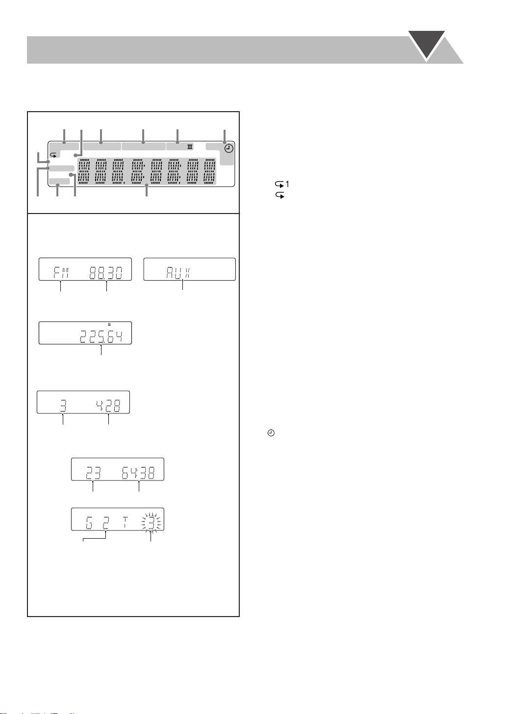
Indications on the main display
• While listening to radio:
S.TURBO
QP Link
Band
FM
Frequency
• While selecting AUX:
S.TURBO
QP Link
Source name
• While listening to DAB:
S.TURBO
QP Link
ST BAND
Frequency
• While playing a CD/MP3*:
S.TURBO
QP Link
Track number
Elapsed playing time
• While disc play is stopped:
CD:
Total track number
MP3:
Group number
S.TURBO
QP Link
S.TURBO
QP Link
Total playing time
MP
3
Track number
* When you start or stop playing an MP3 disc, the group
(folder) number, group (folder) name, track (file)
number, track (file) name (and ID3 Tag) will be shown
before the elapsed playing time appears.
SLEEP
6
123
Disc operation indicators
• PRGM (Program Play): lights when Program Play mode
is activated.
• RND (Random Play): lights when Random Play mode is
activated.
•
Repeat Play:
–: lights when One Track Repeat is activated.
–: lights when All Track Repeat or One Group
Repeat is activated.
2
MP3 indicator
• Lights when an MP3 track is detected.
3
TA/NEWS/INFO—Program type (PTY) indicators
• Lights to indicate the currently selected program type for
PTY Standby Reception.
• Flashes when a program is automatically tuned in with
PTY Standby Reception.
4
Radio reception indicators
• FM: lights while receiving an FM stereo station.
– ST (stereo): lights while an FM stereo station or a DAB
service with sufficient signal strength is tuned in.
– MONO: lights while receiving an FM stereo station in
monaural.
• AM: lights while receiving an AM station.
5
DAB reception indicators
• L-BAND: lights while receiving a DAB ensemble in
L-Band.
• BAND III: lights while receiving a DAB ensemble in
Band III.
6
Timer indicators
•: lights when Daily Timer is on standby; flashes while
working or being set.
• 1/2/3: lights when a Daily Timer (1, 2, or 3) is on standby;
flashes while working or being set.
• SLEEP: lights when Sleep Timer is activated.
7
S.TURBO (Sound Turbo) indicator
• Lights when Sound Turbo is activated.
8
AHB PRO (Active Hyper Bass Pro) indicator
• Lights when AHB Pro is activated.
9
QP Link (Quick Portable Link) indicator
• Lights when QP Link is activated.
p
A.STBY (Auto Standby) indicator
• Lights when Auto Standby is activated.
• Flashes for about 3 minutes before Auto Standby turns
the System off.
q
Main display
6
 Loading...