


AUDIO/VIDEO CONTROL RECEIVER
AUDIO/VIDEO-RECEIVER MIT STEUEREINHEIT AMPLI/TUNER DE COMMANDE AUDIO/VIDEO GEINTEGREERDE AUDIO/VIDEO-VERSTERKER RECEPTOR DE CONTROL DE AUDIO/VÍDEO RICEVITORE DI CONTROLLO AUDIO/VIDEO
RX-774RBK
RM-SR774RU REMOTE CONTROL
TV/CATV |
|
VCR |
SLEEP |
AUDIO |
||
/DBS |
|
|
|
|
||
DVD MULTI |
|
DVD |
VCR |
TV/DBS |
||
CD |
TAPE/MD PHONO |
FM/AM |
||||
SEA |
CNTR TONE |
|
CNTR |
MENU |
||
MODE |
|
1 |
2 |
|
3 |
|
|
|
|
|
|||
SURROUND |
TEST ENTER |
REAR (L) |
|
|||
MODE |
|
4 |
5 |
|
6 |
|
|
|
|
|
|||
SOUND |
EFFECT |
(REAR R) |
|
|||
CONTROL |
|
7/P |
8 |
|
9 |
|
|
|
|
|
|||
CD |
|
DELAY |
|
|
|
|
DISC |
|
10 |
0 |
|
+10 |
|
|
|
|
||||
|
|
RETURN FM MODE/MUTE |
100+ |
|||
AUDIO/TV |
|
|
|
|
|
|
/VCR |
|
|
|
|
|
|
|
|
VOLUME |
|
|
|
|
CATV |
|
|
|
|
|
|
/DBS |
|
|
|
|
|
|
|
|
CHANNEL |
|
|
||
MUTE |
|
|
|
|
|
|
|
|
|
|
PTY + |
|
|
|
|
PTYSEARCH |
FF / ¢ |
|
||
PTY– |
|
PLAY |
|
|
|
|
4/REW |
|
|
|
|
||
|
|
|
|
PAUSE |
|
|
|
|
STOP |
|
|
|
|
REC |
|
|
|
|
|
|
|
|
MODE |
|
|
|
|
|
|
DISPLAY |
TV VOLUME |
|
||
TV/VIDEO |
|
|
|
|
||
|
|
CONTROL |
|
|
|
|
|
|
VCR |
TAPE |
|
|
|
SET |
|
|
|
EXIT |
|
|
O |
|
|
|
|
L |
|
N |
S |
MENU |
|
|
|
|
|
|
RO |
|
|||
|
|
CREEN CONT |
|
|
||
MASTER VOLUME
RX-774R AUDIO/VIDEO CONTROL RECEIVER
|
|
|
|
|
|
|
|
|
– |
+ |
|
|
|
|
|
|
|
|
|
|
|
STANDBY |
|
|
|
|
|
|
|
|
|
|
|
|
|
DOLBY SURROUND |
|
|
|
DVD |
CD |
|
|
|
|
|
|
|
|
|
|
TV SOUND/DBS |
PHONO |
|
|
|
|
EON |
TA/NEWS/INFO |
|
|
|
VCR |
TAPE/MD |
|
STANDBY/ON |
|
|
PTY SEARCH |
DISPLAY MODE |
|
|
|
|
FM |
|
POWER |
|
|
|
|
|
|
|
|
AM |
|
_ ON —OFF |
|
|
|
|
|
|
MULTI JOG |
SOURCE SELECTOR |
|
|
|
|
|
DSP MODE |
SEA MODE |
DVD MULTI/2CH |
FM/AM TUNING |
TUNER PRESET |
|
|
|
|
|
|
|
|
|
TUNER/SEA MEMORY |
FM MODE |
|
|
|
|
|
SPEAKERS |
BALANCE/SURROUND |
|
|
|
|
|
|
|
PHONES |
1 |
2 |
ADJUST |
SEA ADJUST |
SETTING |
|
|
|
|
|
SOUND SELECT LOUDNESS ONETOUCHOPERATION
SOURCENAME
COMPULINK
Remote  ENHANCED COMPULINK CONTROL SYSTEM
INSTRUCTIONS
BEDIENUNGSANLEITUNG MANUEL D’INSTRUCTIONS
GEBRUIKSAANWIJZING MANUAL DE INSTRUCCIONES
ISTRUZIONI
For Customer Use:
Enter below the Model No. and Serial No. which are located either on the rear, bottom or side of the cabinet. Retain this information for future reference.
Model No.
Serial No.
LVT0013-001A
[E]

Warnings, Cautions and Others/Warnung, Achtung und sonstige Hinweise/ Mises en garde, précautions et indications diverses/Waarschuwingen, voorzorgen en andere mededelingen/Avisos, precauciones y otras notas/ Avvertenze e precauzioni da osservare
IMPORTANT for the U.K.
DO NOT cut off the mains plug from this equipment. If the plug fitted is not suitable for the power points in your home or the cable is too short to reach a power point, then obtain an appropriate safety approved extension lead or consult your dealer.
BE SURE to replace the fuse only with an identical approved type, as originally fitted.
If nonetheless the mains plug is cut off ensure to remove the fuse and dispose of the plug immediately, to avoid a possible shock hazard by inadvertent connection to the mains supply.
If this product is not supplied fitted with a mains plug then follow the instructions given below:
IMPORTANT.
DO NOT make any connection to the terminal which is marked with the letter E or by the safety earth symbol or coloured green or green-and-yellow.
The wires in the mains lead on this product are coloured in accordance with the following code:
Blue : Neutral
Brown : Live
As these colours may not correspond with the coloured markings identifying the terminals in your plug proceed as follows:
The wire which is coloured blue must be connected to the terminal which is marked with the letter N or coloured black.
The wire which is coloured brown must be connected to the terminal which is marked with the letter L or coloured red.
IF IN DOUBT - CONSULT A COMPETENT ELECTRICIAN.
Per I’ltalia:
“Si dichiara che il questo prodotto di marca JVC è conforme alle prescrizioni del Decreto Ministeriale n.548 del 28/08/95 pubblicato sulla Gazzetta Ufficiale della Repubblica Italiana n.301 del 28/12/95.”
G-1

CAUTION
To reduce the risk of electrical shocks, fire, etc.:
1.Do not remove screws, covers or cabinet.
2.Do not expose this appliance to rain or moisture.
ACHTUNG
Zur Verhinderung von elektrischen Schlägen, Brandgefahr, usw:
1.Keine Schrauben lösen oder Abdeckungen enternen und nicht das Gehäuse öffnen.
2.Dieses Gerät weder Regen noch Feuchtigkeit aussetzen.
ATTENTION
Afin d’éviter tout risque d’électrocution, d’incendie, etc.:
1.Ne pas enlever les vis ni les panneaux et ne pas ouvrir le coffret de l’appareil.
2.Ne pas exposer l’appareil à la pluie ni à l’humidité.
VOORZICHTIG
Ter vermindering van gevaar voor brand, elektrische schokken, enz.:
1.Verwijder geen schroeven, panelen of de behuizing.
2.Stel dit toestel niet bloot aan regen of vocht.
PRECAUCIÓN
Para reducir riesgos de choques eléctricos, incendio, etc.:
1.No extraiga los tornillos, los cubiertas ni la caja.
2.No exponga este aparato a la lluvia o a la humedad.
ATTENZIONE
Per ridurre il rischio di scosse elettriche, incendi, ecc...
1.Non togliere viti, coperchi o la scatola.
2.Non esporre l’apparecchio alla piogggia e all’umidità.
English
Deutsch
Français
Nederlands
Español
Italiano
G-2

Caution –– POWER switch and STANDBY/ON  button!
This apparatus is provided with a  POWER switch to be able to minimize power consumption for safe use. Therefore,
1.When doing initial setting, complete all the connections required, connect the mains plug into the wall outlet, and set the  POWER switch to ON. After these, it will be available to operate STANDBY/ ON
  button and so on.
2.When not in use, set the  POWER switch to OFF.
3.Disconnect the mains plug to shut the power off completely. The
 POWER switch and STANDBY/ON
  button in any position
do not disconnect the mains line.
4. The power can be remote controlled.
Achtung –– POWER-Schalter und STANDBY/ON  -Taste!
Dieses Gerät hat einen Netzschalter (  POWER), um den Stromverbrauch für sichere Verwendung auf ein Minimum bringen zu können. Verfahren Sie deshalb wie folgt:
1.Beim ursprünglichen Aufbau alle erforderlichen Anschlüsse
herstellen, den Netzstecker in eine Wandsteckdose stecken, und
den  POWER-Schalter einschalten. Anschließend ist Betrieb der STANDBY/ON
  -Taste usw. möglich.
2.Wenn das Gerät nicht verwendet wird, den  POWER-Schalter ausschalten.
3.Den Netzstecker aus der Steckdose ziehen, um die
Stromversorgung vollkommen zu unterbrechen. Der  POWERSchalter und die STANDBY/ON
  -Taste unterbrechen in keiner Stellung die Stromversorgung vollkommen.
4.Die Stromversorgung kann mit der Fernbedienung einund ausgeschaltet werden.
Attention — Commutateur  POWER et d’une touche STANDBY/ ON
  !
!
Cet appareil est équipé d’un commutateur  POWER qui lui permet de réduire sa consommation d’électricité pour une utilisation plus sûre. Par conséquent,
1.En procédant au réglage initial, compléter toutes les connexions
nécessaires, connecter la fiche secteur dans la prise murale et
mettre le commutateur  POWER sur la position ON. Ensuite, il sera possible de contrôler la touche STANDBY/ON
  , etc.
2.Mettre le commutateur  POWER sur la position OFF lorsque l’appareil n’est pas utilisé.
3.Déconnecter la fiche secteur pour couper complètement le courant.
Le commutateur  POWER et la touche STANDBY/ON
  ne coupent jamais complètement l’alimentation, quelle que soit leurs positions.
4.L’alimentation peut être télécommandée.
Voorzichtig –– POWER en STANDBY/ON |
schakelaars! |
Dit apparaat is voorzien van een  POWER hoofdschakelaar om het apparaat gebruiksklaar te zetten, maar te zorgen dat het stroomverbruik minimaal blijft. Neem in verband hiermee het volgende in acht:
1.Bij de eerste ingebruikneming zorgt u eerst dat alle aansluitingen
in orde zijn, dan steekt u de stekker in het stopkontakt en dan zet
u de  POWER schakelaar in de “ON” stand. Daarna kunt u het apparaat aanen uitschakelen met de STANDBY/ON
  schakelaar.
2.Wanneer u het apparaat geruime tijd niet gebruikt, kunt u beter de
 POWER schakelaar in de “OFF” stand zetten.
3.Om de stroomtoevoer geheel uit te schakelen, trekt u de stekker uit het stopkontakt. Anders zal er altijd een geringe hoeveelheid
stroom naar het apparaat lopen, ongeacht de stand van de STANDBY/ON  en de
en de  POWER.
4.U kunt het apparaat ook met de afstandsbediening aanen uitschakelen.
Precaución –– Interruptor POWER y botón STANDBY/ON  !
!
Esta unidad dispone de un interruptor  POWER que sirve para reducir al mínimo el consumo de alimentación para proporcionar mayor seguridad operacional. Por lo tanto,
1.Al ejecutar el ajuste inicial, después de completar todas las
conexiones requeridas, conectar el cable de alimentación a una toma de pared, y activar el interruptor  POWER. Entonces, será posible ejecutar operaciones tales como la conmutación del estado de alimentación.
2.Desactivar el interruptor  POWER al dejar la unidad fuera de uso.
3.Desconectar el cable de alimentación para desactivar la
alimentación totalmente. Cualquier que sea la posición de ajustes del interruptor  POWER y el botón STANDBY/ON
  , la alimentación no es cortada completamente.
4.La alimentación puede ser controlada remotamente.
Attenzione –– Interruttore POWER e tasto STANDBY/ON  !
!
Per ridurre al minimo l’assorbimento di corrente ai fini della sicurezza, questo apparecchio è stato dodato di un interruttore  POWER. Di conseguenza,
1.Al momento dell’impostazione iniziale, completare tutti i collegamenti richiesti, inserire la spina del cavo di alimentazione
nella presa a muro della rete elettrica e impostare l’interruttore
 POWER in posizione ON. Fatto ciò, sarà pronto all’uso STANDBY/ON
  .
.
2.Quando non in uso, impostare l’interruttore  POWER in posizione OFF.
3.Disinserire la spina del cavo di alimentazione dalla presa della rete
elettrica per staccare completamente l’alimentazione. L’ interruttore
 POWER e il tasto STANDBY/ON
  in nessuna posizione staccano la linea di alimentazione elettrica principale.
4.È possibile il controllo remoto dell’alimentazione.
G-3

Caution: Proper Ventilation
To avoide risk of electric shock and fire and to protect from damage.
Locate the apparatus as follows:
Front: |
No obstructions open spacing. |
Sides: |
No obstructions in 10 cm from the sides. |
Top: |
No obstructions in 10 cm from the top. |
Back: |
No obstructions in 15 cm from the back |
Bottom: |
No obstructions, place on the level surface. |
In addition, maintain the best possible air circulation as illustrated.
Achtung: Angemessene Ventilation
Stellen Sie das Gerät zur Verhütung von elektrischem Schlag und
Feuer und zum Schutz gegen Beschädigung wie folgt auf: Vorderseite: Offener Platz ohne Hindernisse.
Seiten: Keine Hindernisse innerhalb 10 cm von den Seiten.
Oberseite: Keine Hindernisse innerhalb 10 cm von der Oberseite. Rückseite: Keine Hindernisse innerhalb 15 cm von der Rückseite.
Unterseite: Keine Hindernisse. Auf eine ebene Oberfläche stellen.
Zusätzlich die bestmögliche Luftzirkulation wie gezeigt erhalten.
Attention: Ventilation Correcte
Pour éviter les chocs électriques, l’incendie et tout autre dégât. Disposer l’appareil en tenant compte des impératifs suivants
Avant: |
Rien ne doit gêner le dégagement |
Flancs: |
Laisser 10 cm de dégagement latéral |
Dessus: |
Laisser 10 cm de dégagement supérieur |
Arrière: |
Laisser 15 cm de dégagement arrière |
Dessous: |
Rien ne doit obstruer par dessous; poser l’appareil sur |
une surface plate.
Veiller également à ce que l’air circule le mieux possible comme illustré.
Voorzichtig: Zorg Voor Goede Ventilatie
Om gevaar voor brand of een elektrische schok te voorkomen, dient u bij opstelling van het apparaat op de volgende punten te letten:
Voorkant: |
Voldoende ruimte vrij houden. |
Zijkanten: |
Minstens 10 cm aan weerszijden vrij houden. |
Bovenkant: |
Niets bovenop plaatsen; 10 cm speling geven. |
Achterkant: Minstens 15 cm ruimte achteraan vrij houden. Onderkant: Opstellen op een egaal horizontaal oppervlak.
Bovendien moet er rondom voldoende luchtdoorstroming zijn, zoals in de afbeelding aangegeven.
Precaución: Ventilación Adecuada
Para evitar el riesgo de choque eléctrico e incendio y para proteger el aparato contra daños.
Ubique el aparato de la siguiente manera:
Frente: |
Espacio abierto sin obstrucciones |
Lados: |
10 cm sin obstrucciones a los lados |
Parte superior: |
10 cm sin obstrucciones en la parte superior |
Parte trasera: |
15 cm sin obstrucciones en la parte trasera |
Fondo: |
Sin obstrucciones, colóquelo sobre una superficie |
|
nivelada |
Además, mantenga la mejor circulación de aire posible como se ilustra.
Attenzione: Problemi di Ventilazione
Per evitare il rischio di folgorazioni ed incendi e proteggere l’unità da danni, installarla nel modo seguente.
Davanti: |
Nessun ostacolo, spazio libero |
Lati: |
Nessun ostacolo per almeno 10 cm |
Sopra: |
Nessun ostacolo per almeno 10 cm |
Retro: |
Nessun ostacolo per almeno 15 cm |
Fondo: |
Libero ed in piano |
Inoltre, mantenere il più possibile la circolazione dell’aria.
Spacing 15 cm or more Abstand von 15 cm oder mehr Dégagement de 15 cm ou plus Minstens 15 cm tussenruimte Espacio de 15 cm o más
15 cm di distanza o più
RX-774RBK
Wall or obstructions
Wand oder Hindernisse
Mur, ou obstruction
Wand of meubilair
Pared u obstrucciones
Parete o ostacol
Floor
Boden
Plancher
Vloer
Piso
Pavimento
Front
Vorderseite
Avant
Voorkant
Frente
Davanti
Stand height 15 cm or more Standhöhe 15 cm oder mehr Hauteur du socle: 15 cm ou plus
Standard op minstens 15 cm van de vloer Allura del soporte 15 cm o más
Altezza del tavolino 15 cm p plù
G-4

English

 Table of Contents
Parts Identification...................................................................................... |
3 |
Easy Set Up & Operations ............................................................................ |
5 |
Getting Started........................................................................................... |
9 |
Before Installation ................................................................................................................................................................... |
9 |
Checking the Supplied Accessories ........................................................................................................................................ |
9 |
Connecting the FM and AM (MW/LW) Antennas ............................................................................................................... |
10 |
Connecting the Speakers ....................................................................................................................................................... |
11 |
Connecting Audio/Video Components ................................................................................................................................. |
14 |
Connecting the Power Cord .................................................................................................................................................. |
19 |
Putting Batteries in the Remote Control ............................................................................................................................... |
19 |
Basic Operations ....................................................................................... |
20 |
Turning the Power On and Off (Standby) ............................................................................................................................. |
20 |
Selecting the Source to Play ................................................................................................................................................. |
20 |
Adjusting the Volume ............................................................................................................................................................ |
21 |
Selecting the Front Speakers ................................................................................................................................................. |
22 |
Muting the Sound .................................................................................................................................................................. |
22 |
Recording a Source ............................................................................................................................................................... |
22 |
Basic Settings........................................................................................... |
23 |
Changing the Source Name .................................................................................................................................................. |
23 |
Adjusting the Front Speaker Output Balance ....................................................................................................................... |
23 |
Listening at Low Volume (Loudness) ................................................................................................................................... |
23 |
Using the Sleep Timer ........................................................................................................................................................... |
24 |
Setting Center and Rear Speakers for DSP Modes ............................................................................................................... |
24 |
One Touch Operation .................................................................................. |
26 |
About the One Touch Operation ........................................................................................................................................... |
26 |
Using the One Touch Operation ............................................................................................................................................ |
26 |
Receiving Radio Broadcasts ........................................................................ |
27 |
Tuning in Stations Manually ................................................................................................................................................. |
27 |
Using Preset Tuning .............................................................................................................................................................. |
27 |
Selecting the FM Reception Mode ....................................................................................................................................... |
29 |
Assigning Names to Preset Stations ..................................................................................................................................... |
30 |
Using the RDS (Radio Data System) to Receive FM Stations ............................................................................................. |
31 |
What Information Can RDS Signals Provide? ...................................................................................................................... |
31 |
Searching for a Program by PTY Codes ............................................................................................................................... |
32 |
Switching to a Broadcast Program of Your Choice Temporarily .......................................................................................... |
34 |
1

English
Using the SEA Modes ................................................................................ |
36 |
Selecting Your Favorite SEA Mode ...................................................................................................................................... |
36 |
Creating Your Own SEA Mode ............................................................................................................................................. |
37 |
Using the DSP Modes ................................................................................ |
38 |
Using the 3D-PHONIC Modes ............................................................................................................................................. |
39 |
Using the DAP Modes .......................................................................................................................................................... |
41 |
Preparing for Surround Modes ............................................................................................................................................. |
44 |
Using Surround Modes ......................................................................................................................................................... |
48 |
Using the DVD MULTI Playback Mode .......................................................... |
49 |
Speaker Arrangements for DVD MULTI Playback .............................................................................................................. |
49 |
Activating the DVD MULTI Playback ................................................................................................................................. |
49 |
Using the On-Screen Menus........................................................................ |
52 |
Selecting the Source to Play ................................................................................................................................................. |
52 |
Selecting the Different Sources for Picture and Sound ........................................................................................................ |
52 |
Using the DSP Modes ........................................................................................................................................................... |
52 |
Adjusting the Front Speaker Output Balance ....................................................................................................................... |
53 |
Listening at Low Volume (Loudness) ................................................................................................................................... |
53 |
Adjusting the DSP Modes ..................................................................................................................................................... |
53 |
Selecting Your Favorite SEA Mode ...................................................................................................................................... |
54 |
Creating Your Own SEA Mode ............................................................................................................................................. |
55 |
Setting the Center Speaker Size ............................................................................................................................................ |
55 |
Setting the Rear Speaker ....................................................................................................................................................... |
56 |
Setting the Delay Time ......................................................................................................................................................... |
56 |
Operating the Tuner .............................................................................................................................................................. |
56 |
Storing the Preset Stations .................................................................................................................................................... |
57 |
Assigning Names to the Preset Stations ............................................................................................................................... |
57 |
Checking the RDS Information ............................................................................................................................................ |
58 |
COMPU LINK Remote Control System ......................................................... |
59 |
TEXT COMPU LINK Remote Control System................................................. |
60 |
Showing the Disc Information on the TV Screen ................................................................................................................. |
61 |
Searching a Disc (Only for the CD player) ........................................................................................................................... |
62 |
Using the User File (Only for the CD Player with the User File Function) ......................................................................... |
64 |
Entering the Disc Information .............................................................................................................................................. |
65 |
Operating JVC’s Audio/Video Components ................................................... |
67 |
Operating Other Manufactures’ Components ............................................... |
70 |
Troubleshooting......................................................................................... |
76 |
Specifications............................................................................................ |
77 |
2
English

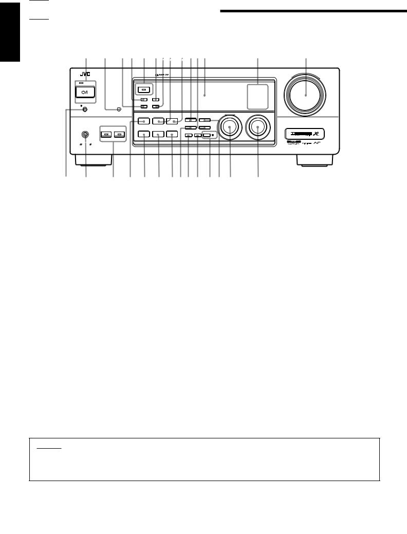
 Parts Identification
Become familiar with the buttons and controls on the receiver before use.
1 2 3 4 5 678 9 0-= |
~ |
|
! |
||||||||
|
|
|
|
|
|
|
|
|
|
|
MASTER VOLUME |
|
RX-774R AUDIO/VIDEO CONTROL RECEIVER |
|
|
|
|
|
|
|
|
||
|
|
|
|
|
|
|
|
|
|
– |
+ |
|
|
|
|
|
|
|
|
|
|
|
|
STANDBY |
|
|
|
|
|
|
|
|
|
|
|
|
|
|
DOLBY SURROUND |
|
|
|
|
DVD |
CD |
|
|
|
|
|
|
|
|
|
|
TV SOUND/DBS |
PHONO |
|
|
|
|
|
EON |
TA/NEWS/INFO |
|
|
|
VCR |
TAPE/MD |
|
|
|
|
|
|
|
|
|
|
|
|
||
STANDBY/ON |
|
|
|
|
|
|
|
|
FM |
|
|
|
|
|
|
|
|
|
|
|
|
|
|
|
|
|
PTY SEARCH DISPLAY MODE |
|
|
|
|
AM |
|
|
|
POWER |
|
|
|
|
|
|
|
|
|
|
|
|
|
|
|
|
|
|
|
|
|
|
|
_ON —OFF |
|
|
|
|
|
|
MULTI JOG |
SOURCE SELECTOR |
|
|
|
|
|
|
DSP MODE |
SEA MODE |
DVD MULTI/2CH |
FM/AM TUNING |
TUNER PRESET |
|
|
|
|
|
|
|
|
|
|
TUNER/SEA MEMORY |
FM MODE |
|
|
|
|
|
|
SPEAKERS |
BALANCE/SURROUND |
|
|
|
|
|
|
|
|
PHONES |
1 |
2 |
ADJUST |
SEA ADJUST |
SETTING |
|
|
|
|
|
|
|
|
|
|
|
|
SOUND SELECT LOUDNESS ONETOUCHOPERATION |
|
|
|
|
|
|
|
|
|
|
|
SOURCENAME |
|
|
|
|
|
COMPULINK |
|
|
|
|
|
|
|
|
|
|
|
Remote |
ENHANCED COMPULINK CONTROL SYSTEM |
|
|
|
|
|
|
|
|
|
|
@ # |
$ % ^ & * ( ) _ + ¡ ™ |
£ |
Refer to the pages in parentheses for details.
Front Panel
1 STANDBY/ON  button and STANDBY lamp (20) 2 Remote sensor (19)
3 PTY SEARCH button (32) *
4 EON button (34)
5 DOLBY SURROUND button and lamp (46)
6 TA/NEWS/INFO button (34)
7 DISPLAY MODE button (31)
8 SEA MODE button (36) *
9 DVD MULTI/2CH button (20)
0 FM/AM TUNING button (27) * - FM MODE button (29)
= Display (20)
~ Source lamps (20)
! MASTER VOLUME control (21)
@  POWER switch (19)
# PHONES jack (22)
$ SPEAKERS 1/2 buttons and lamps (22) % DSP MODE button (39) *
^ BALANCE/SURROUND ADJUST button (23, 39) * & SEA ADJUST button (37) *
* SETTING button (24) *
( TUNER/SEA MEMORY button (27, 37) ) SOUND SELECT button (21)
_ LOUDNESS/SOURCE NAME button (23)
+ ONE TOUCH OPERATION button and lamp (26) ¡ TUNER PRESET button (28) *
™ MULTI JOG control (23)
£ SOURCE SELECTOR control (20)
IMPORTANT:
To use the MULTI JOG control (™) on the front panel:
What this control actually does depends on which function you are trying to adjust. Before using this control, select the function by pressing one of the buttons marked with *.
3
|
RM-SR774RU REMOTE CONTROL |
||
|
TV/CATV |
VCR |
AUDIO |
¢ |
/DBS |
|
SLEEP |
|
|
|
|
|
DVD MULTI |
DVD |
VCR TV/DBS |
CD TAPE/MD PHONO FM/AM
SEA |
CNTR TONE |
CNTR |
MENU |
MODE |
|
|
§1 2 3
SURROUND TEST ENTER  REAR (L)
MODE
¶4 
 5
5  6
6
|
SOUND |
EFFECT |
|
(REAR R) |
|||
• |
CONTROL |
7/P |
8 |
|
9 |
||
CD |
|
||||||
|
DELAY |
|
|
|
|
||
ª |
DISC |
10 |
|
0 |
|
+10 |
|
|
|
|
|||||
|
|
RETURN FM MODE/MUTE |
100+ |
||||
|
AUDIO/TV |
|
|
|
|
|
|
º |
/VCR |
|
|
|
|
|
|
|
VOLUME |
|
|
|
|||
|
CATV |
|
|
|
|
|
|
|
/DBS |
|
|
|
|
|
|
|
|
CHANNEL |
|
||||
– |
MUTE |
|
|
|
|
|
+ |
|
|
|
|
|
PTY |
||
|
PTY |
SEARCH |
|
FF / ¢ |
|||
|
Y– |
PLAY |
|
|
|
|
|
|
PT |
|
|
|
|
|
|
|
/REW |
|
|
|
|
|
|
|
4 |
|
|
|
|
|
|
|
|
|
STOP |
|
PAUSE |
||
|
|
|
|
|
|
||
|
REC |
|
|
|
|
|
|
|
|
|
TV |
|
|
|
|
|
|
DISPLAY |
MODE |
|
|
||
|
|
|
VOLUME |
||||
|
TV/VIDEO |
|
|
|
|
|
|
|
|
CONTROL |
|
|
|
||
|
|
VCR |
|
TAPE |
|
||
|
SET |
|
|
|
|
|
EXIT |
O |
|
|
|
|
L |
N |
S |
|
|
|
O |
|
|
T |
|||
|
|
C |
N |
R |
|
|
|
R |
|
||
|
|
|
EEN CO |
|
|
English
Ÿ
⁄
¤
‹
›
fi
fl
‡
°
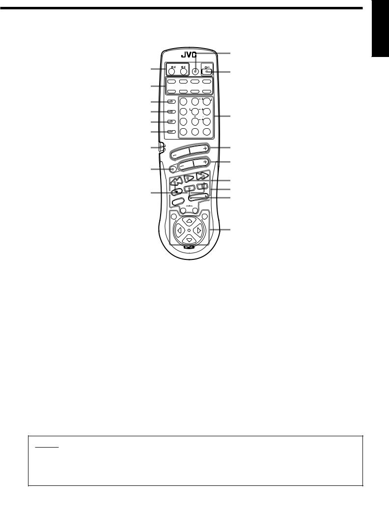
Refer to the pages in parentheses for details.
Remote Control
¢ TV/CATV/DBS  and VCR
  buttons (70, 72)
Source selecting buttons (21) § SEA MODE button (36)
¶ SURROUND MODE button (40)
• SOUND CONTROL button (40, 43, 44, 51) ª CD DISC button (68)
º Remote control mode selector (AUDIO/TV/VCR, CATV/ DBS) (20)
– MUTE button (22)
PTY buttons (+/–) (33)
Ÿ SLEEP button (24)
⁄ AUDIO  button (20)
¤10 keys for selecting preset channel (28)
10 keys for adjusting sound (40, 43, 44, 51)
10 keys for operating audio/video components (67, 70)
‹ VOLUME buttons (+/–) (21) › CHANNEL buttons (+/–) (69) fi PTY SEARCH button (33)
fl Operating buttons for audio/video components (67, 70)
‡ DISPLAY MODE button (31)
° MENU operation buttons (SET, EXIT, %, fi, @, #) (52)
IMPORTANT:
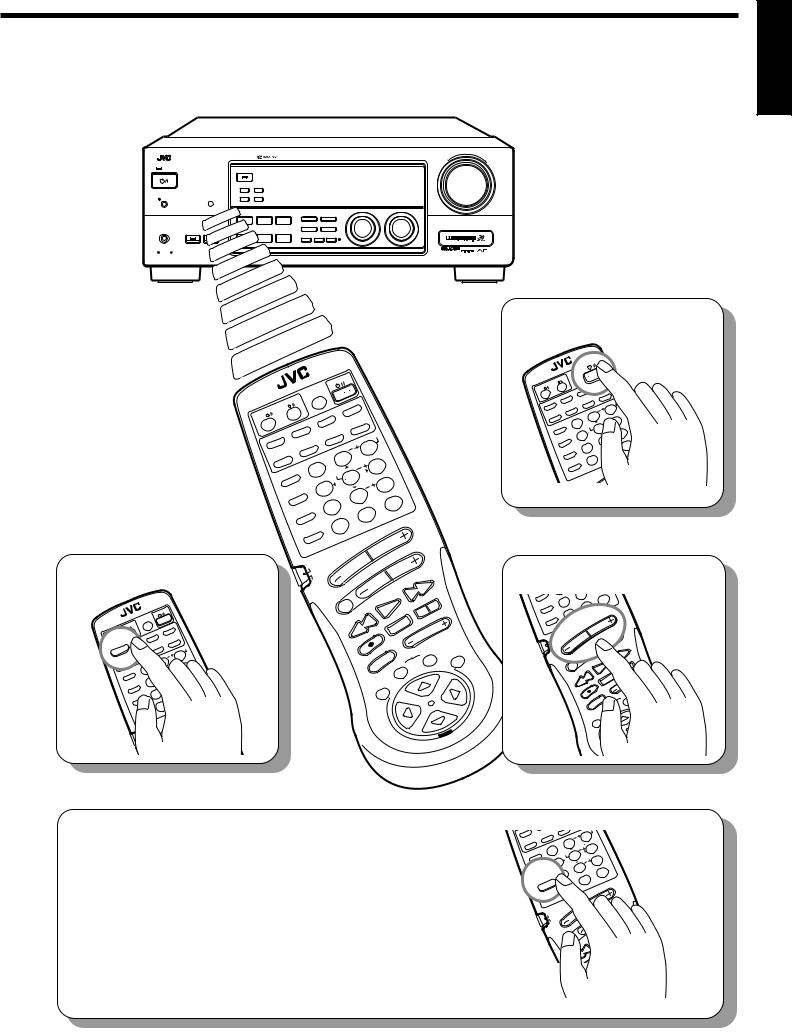
When using the remote control:
Check to see if its remote control mode selector (º) is set to the correct position.
To operate an audio system, TV, and VCR, set it to “AUDIO/TV/VCR.”
To operate a CATV converter and DBS (Direct Broadcasting Satellite) tuner, set it to “CATV/DBS.”
4
English

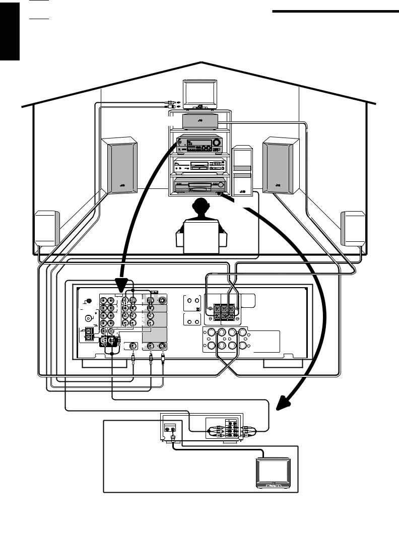
 Easy Set Up & Operations
If you are already familiar with audio components, following four pages just you opened give you enough information to operate your RX-774RBK for enjoyment of surround sound in your listening room.
|
TV |
To video input |
|
To S-video input |
|
Center Speaker |
|
Front Speaker |
Front Speaker |
Rear Speaker |
Subwoofer |
Rear Speaker |
|
Speaker Signal Cable |
Speaker Signal Cable |
|
|
|
|
|
|
|
|
|
|
|
RX-774RBK |
Speaker Signal |
|
|
|
|
|
|
|
|
|
|
|
|
Cable |
|
RIGHT |
LEFT |
AUDIO RIGHT |
LEFT |
VIDEO |
S-VIDEO |
TEXT |
|
|
|
|
|
|
COMPU LINK |
CENTER |
|
REAR |
|
|
||||||
|
|
|
PHONO |
|
|
|
|
|
|
|
||
GND |
|
|
|
DVD |
|
|
SPEAKER |
SPEAKERS |
|
|
||
|
|
|
|
|
|
|
|
|
||||
|
|
|
|
|
|
|
|
|
RIGHT |
LEFT |
|
|
|
|
|
CD |
|
TV SOUND |
|
1 (MASTER UNIT) |
|
|
|
|
|
ANTENNA |
|
|
/DBS |
|
2 (SLAVE UNIT) |
|
|
|
|
|
||
|
FM 75 |
|
OUT |
|
OUT |
|
COMPU LINK-3 |
|
|
|
|
|
|
COAXIAL |
|
|
|
(SYNCHRO) |
|
|
|
|
|
||
|
|
(REC) |
|
(REC) |
|
|
|
|
|
|
||
|
|
|
|
|
|
|
|
|
|
|
||
|
|
|
TAPE |
|
VCR |
|
|
|
|
|
|
|
|
|
|
/MD |
|
|
|
|
|
|
|
|
|
|
GND |
|
IN |
|
IN |
|
|
|
|
|
|
|
|
|
|
(PLAY) |
|
(PLAY) |
|
|
|
|
|
|
|
GND |
|
|
|
|
|
|
|
|
|
|
|
|
AM |
|
|
CENTER |
|
|
|
|
1 |
|
|
|
|
SUB |
|
|
|
|
|
|
|
|
1 |
|
||
LOOP |
|
DVD |
|
|
|
|
|
|
|
|
||
|
WOOFER |
|
|
|
|
|
|
+ |
– |
– |
+ |
|
|
AM |
|
|
|
|
|
|
|
||||
|
EXT |
|
|
|
|
|
|
|
|
|
|
|
|
|
|
SUBWOOFER |
|
MONITOR |
|
|
2 |
|
|
2 |
|
|
|
|
OUT |
|
OUT |
|
|
|
|
|
||
|
|
|
|
|
|
|
|
RIGHT |
|
|
LEFT |
|
|
|
|
|
|
|
|
|
|
|
|
FRONT SPEAKERS |
|
Speaker Signal |
Speaker Signal |
Cable |
Cable |
|
VCR |
|
To audio/video input |
|
|
|
IN OUT |
|
|
S-VIDEO |
|
ANTENNA |
|
|
IN OUT |
VIDEO |
To audio/video |
|
AUDIO |
|
|
L |
|
|
AUDIO |
output |
|
R |
|
|
|
|
To RF output |
To TV antenna |
TV |
|
||
|
|
|
|
input |
|
If your TV does not have a video input |
|
|
5

English
MASTER VOLUME
RX-774R AUDIO/VIDEO CONTROL RECEIVER
|
|
|
|
|
|
|
|
|
– |
+ |
STANDBY |
|
|
|
|
|
|
|
|
|
|
|
|
|
DOLBY SURROUND |
|
|
|
DVD |
CD |
|
|
|
|
|
|
|
|
|
|
TV SOUND/DBS |
PHONO |
|
|
|
|
EON |
TA/NEWS/INFO |
|
|
|
VCR |
TAPE/MD |
|
STANDBY/ON |
|
|
|
|
|
|
|
|
FM |
|
|
|
|
PTY SEARCH |
DISPLAY MODE |
|
|
|
|
|
|
POWER |
|
|
|
|
|
|
|
|
AM |
|
_ ON —OFF |
|
|
|
|
|
|
MULTI JOG |
SOURCE SELECTOR |
|
|
|
|
|
DSP MODE |
SEA MODE |
DVD MULTI/2CH |
FM/AM TUNING |
TUNER PRESET |
|
|
|
|
|
|
|
|
|
TUNER/SEA MEMORY |
FM MODE |
|
|
|
|
|
SPEAKERS |
BALANCE/SURROUND |
|
|
|
|
|
|
|
PHONES |
1 |
2 |
|
|
|
|
|
|
||
ADJUST |
SEA ADJUST |
SETTING |
|
|
|
|
|
|||
SOUND SELECT LOUDNESS ONETOUCHOPERATION
SOURCENAME
COMPULINK
Remote  ENHANCED COMPULINK CONTROL SYSTEM
2. Select the source.
|
|
|
|
CONTROL |
||
|
|
|
REMOTE |
|
|
AUDIO |
-SR774RU |
SLEEP |
|
|
|||
RM |
|
VCR |
|
|
|
|
TV/CATV |
|
|
VCR |
|||
/DBS |
|
|
|
|
|
|
|
|
|
DVD |
PHONO |
||
|
DVD |
|
|
|||
|
|
|
TAPE/MD |
|
|
|
|
CD |
|
TONE |
|
||
|
|
|
|
|
||
|
|
|
CNTR |
|
|
|
|
|
SEA |
1 |
|
ENTER |
|
|
|
MODE |
|
|
||
|
|
TEST |
|
|||
|
|
SURROUNDMODE |
4 |
|
||
|
|
|
SOUND |
EFFECT |
||
|
|
|
|
7 |
||
|
|
|
CONTROL |
|
/P |
|
|
|
|
|
DELAY |
||
|
|
|
CD |
|
10 |
|
|
|
|
DISC |
|
|
|
|
|
|
AUDIO/TV |
|||
|
|
|
|
/VCR |
|
|
|
|
|
|
CATV |
|
|
|
|
|
|
/DBS |
|
|
|
|
|
CONTROL |
|
|
|
|
|
|
|
|
|
|
|
|
|
||
|
|
REMOTE |
|
|
AUDIO |
|
|
|
|
|
|
|
|
|
|
|
|
|
|
|
|
|
|
|
|
|
|
|
|
|
|
|
|
|
|
|
|
-SR774RU |
SLEEP |
|
|
|
|
|
|
|
|
|
|
|
|
|
|
|||
RM |
VCR |
|
|
TV/DBS |
|
|
|
|
|
|
|
|
|
|
||||
TV/CATV |
|
|
|
|
|
|
|
|
|
|
|
|
|
|||||
|
|
VCR |
|
|
|
|
|
|
|
|
|
|
|
|
|
|||
/DBS |
|
|
|
|
|
|
|
|
|
|
|
|
|
|
|
|
||
|
|
|
|
|
|
FM/AM |
|
|
|
|
|
|
|
|
|
|||
|
|
DVD |
|
|
|
|
|
|
|
|
|
|
|
|
|
|||
DVD |
MULTI |
|
|
PHONO |
|
|
|
|
MENU |
|
|
|
|
|
|
|
||
|
TAPE/MD |
|
CNTR |
3 |
|
|
|
|
|
|
|
|
||||||
|
|
|
|
|
|
|
|
|
|
|
||||||||
|
CD |
|
|
|
2 |
|
|
|
|
|
|
|
|
|
|
|||
|
|
TONE |
|
|
(L) |
|
|
|
|
|
|
|
|
|||||
|
|
|
|
|
|
|
|
|
|
|
|
|
||||||
|
|
CNTR |
|
REAR |
6 |
|
|
|
|
|
|
|
||||||
|
|
|
|
|
|
|
|
|
|
|
|
|||||||
|
SEA |
1 |
ENTER |
5 |
|
|
|
|
|
|
|
|
|
|||||
|
|
|
|
|
|
|
|
|
|
|
|
|||||||
|
MODE |
|
|
|
|
|
R) |
|
|
|
|
|
|
|
||||
|
TEST |
|
|
|
|
|
|
|
|
|
|
|
||||||
|
|
|
|
|
|
(REAR |
9 |
|
|
|
|
|
|
|||||
|
SURROUND |
|
4 |
|
|
|
|
|
|
|
|
|
||||||
|
|
|
|
|
|
|
|
|
|
|
|
|
|
|||||
|
|
MODE |
|
|
|
8 |
|
|
|
|
|
|
|
|
|
|||
|
|
|
EFFECT |
|
|
|
|
|
|
|
|
|
|
|||||
|
|
|
|
|
|
+10 |
|
|
|
|
|
|
||||||
|
|
SOUND |
|
7 |
|
|
|
|
|
|
|
|
|
|
|
|||
|
|
CONTROL |
|
/P |
|
|
|
0 |
|
|
|
|
|
|
|
|
||
|
|
|
DELAY |
|
|
|
|
100+ |
|
|
|
|
|
|
||||
|
|
|
|
|
|
|
|
MODE/MUTE |
|
|
|
|
|
|
|
|||
|
|
CD |
|
10 |
|
|
|
|
|
|
|
|
|
|||||
|
|
|
|
FM |
|
|
|
|
|
|
|
|
|
|||||
|
|
DISC |
RETURN |
|
|
|
|
|
|
|
|
|
|
|
||||
|
|
|
|
|
|
|
|
|
|
|
|
|
|
|
|
|||
|
|
AUDIO/TV |
VOLUME |
|
|
|
|
|
|
|
|
|
||||||
|
|
|
|
|
CHANNEL |
+ |
|
|
|
|
|
|||||||
|
|
|
/VCR |
|
|
|
|
|
|
|
|
|
||||||
|
|
|
|
|
|
|
|
|
|
|
|
|
PTY |
|
|
|
|
|
|
|
|
CATV |
|
|
|
|
|
|
|
|
/¢ |
|
|
|
|
||
|
|
|
|
|
|
|
|
|
|
|
FF |
|
|
|
|
|
||
|
|
|
|
/DBS |
MUTE |
|
|
|
|
SEARCH |
|
|
|
|
|
|
||
|
|
|
|
|
|
|
|
|
|
|
|
|
|
|
||||
|
|
|
|
|
|
|
|
|
|
PTY PLAY |
|
|
PAUSE |
|
|
|
|
|
|
|
|
|
|
|
|
– |
|
|
|
|
|
|
|
|
|
|
|
|
|
|
|
|
|
|
PTY/REW |
|
|
STOP |
|
|
|
|
|
|
||
|
|
|
|
|
|
|
4 |
|
|
|
|
|
VOLUME |
|
|
|
|
|
|
|
|
|
|
|
|
|
|
|
|
|
MODETV |
|
|
|
|
||
|
|
|
|
|
|
|
|
|
|
|
|
|
|
|
|
|
||
|
|
|
|
|
|
|
|
|
|
|
|
|
|
|
|
|
|
|
|
|
|
|
|
|
|
|
|
REC |
TV/VIDEO |
DISPLAY |
|
|
|
|
|
||
|
|
|
|
|
|
|
|
|
|
CONTROL |
|
|
EXIT |
|
||||
|
|
|
|
|
|
|
|
|
|
|
|
|
|
TAPE |
|
|
|
|
|
|
|
|
|
|
|
|
|
|
|
|
VCR |
|
|
|
|
|
|
|
|
|
|
|
|
|
|
|
|
|
SET |
|
|
|
|
|
|
|
|
|
|
|
|
|
|
|
|
|
|
|
|
|
|
|
|
R |
O |
|
|
|
|
|
|
|
|
|
|
|
|
|
|
|
|
|
|
|
|
|
|
|
|
|
|
|
|
|
|
|
|
|
|
|
|
T |
|
|
|
|
|
|
|
|
|
|
|
|
|
|
|
|
|
|
N |
|
|
|
|
|
|
|
|
|
|
|
|
|
|
|
|
|
MENU O |
|
|
|
|
|
|
|
|
|
|
|
|
|
|
|
|
|
|
|
C |
|
|
|
|
|
|
|
|
|
|
|
|
|
|
|
|
|
|
N |
|
|
|
|
|
|
|
|
|
|
|
|
|
|
|
|
|
E |
|
|
|
|
|
|
|
|
|
|
|
|
|
|
|
|
|
E |
|
|
|
|
|
|
|
|
|
|
|
|
|
|
|
|
ON SCR |
|
|
|
||
L
1. Turn on the power.
|
REMOTE |
CONTROLAUDIO |
|
|
|
|
|||||
|
|
|
|
|
|
|
|
|
|
||
-SR774RU |
SLEEP |
|
|
|
|
|
|
|
|
||
RM |
VCR |
|
|
|
TV/DBS |
|
|
|
|||
TV/CATV |
|
|
|
|
|
|
|||||
|
VCR |
|
|
|
|
|
|
||||
/DBS |
|
|
|
FM/AM |
|
|
|||||
|
DVD |
|
|
|
|
|
|
||||
DVD |
MULTI |
|
PHONO |
|
|
|
|
MENU |
|||
TAPE/MD |
|
|
CNTR |
3 |
|
||||||
|
|
|
|
||||||||
|
CD |
|
TONE |
2 |
|
|
(L) |
|
|||
|
|
CNTR |
|
REAR |
6 |
||||||
|
|
|
|
|
|||||||
|
SEA |
|
1 |
|
ENTER |
5 |
|
|
|||
|
MODE |
|
|
|
|
|
|
R) |
|||
|
|
TEST |
|
(REAR |
|||||||
|
SURROUNDMODE |
4 |
|
|
|
9 |
|||||
|
|
|
|
|
8 |
|
|
||||
|
|
|
EFFECT |
|
|
+10 |
|||||
|
SOUND |
|
|
/P |
|
|
|
|
|
||
|
|
7 |
|
|
|
0 |
|
||||
|
CONTROL |
|
DELAY |
|
|
|
100+ |
||||
|
|
CD |
|
10 |
|
|
MODE/MUTE |
||||
|
|
DISC |
|
|
FM |
|
|
||||
|
|
|
|
|
RETURN |
|
|
|
|
||
|
|
AUDIO/TV |
VOLUME |
|
NNEL |
||||||
|
|
|
/VCR |
|
|
|
|
|
|
|
|
|
|
|
|
|
|
|
|
|
|
HA |
|
3. Adjust the volume.
S MO |
|
|
CT |
8 |
|
|
|
EFFE |
|
+10 |
|
SOUND |
|
|
/P |
|
|
|
7 |
0 |
|
||
CONTROL |
|
DELAY |
100+ |
||
CD |
|
10 |
MODE/MUTE |
|
|
DISC |
FM |
|
|||
|
|
|
RETURN |
|
|
AUDIO/TV |
VOLUME |
|
|||
|
/VCR |
|
|
|
|
|
CATV |
|
|
|
|
|
|
/DBS |
MUTE |
|
|
|
|
|
PTY |
|
|
|
|
|
|
– |
|
|
|
|
|
PTY/REW |
|
|
|
|
|
4 |
|
|
|
|
|
REC |
|
|
|
|
|
TV/VIDEO |
|
4. Select an appropriate DSP mode.
|
NTR |
|
|
AR |
( |
|
|
|
|
6 |
|||
|
C |
|
RE |
|
|
|
SEA |
1 |
ENTER |
5 |
|
|
|
MODE |
|
|
|
R) |
||
TEST |
|
(REAR |
||||
SURROUND |
|
|
9 |
|||
|
|
|
|
|||
|
|
|
|
|
||
MODE |
|
|
|
|
|
|
SOUND |
|
|
|
|
|
|
CONTROL |
|
|
|
|
|
|
|
CD |
|
|
|
|
|
|
DISC |
|
|
|
|
|
5. DSP mode settings are preset at the factory.
However, if you need to make further adjustments, see pages 39 to 47.
|
|
CONTROL |
|
|
|
|
|
||
|
REMOTE |
|
AUDIO |
|
|
|
|
||
-SR774RU |
SLEEP |
|
|
|
|
|
|
||
RM |
VCR |
|
|
TV/DBS |
|
|
|||
TV/CATV |
|
|
|
|
|||||
|
VCR |
|
|
|
|
|
|||
/DBS |
|
|
|
|
|
FM/AM |
|
||
|
DVD |
|
|
|
|
||||
DVD |
MULTI |
|
PHONO |
|
|
|
MENU |
||
TAPE/MD |
|
CNTR |
3 |
||||||
|
|
||||||||
|
CD |
|
TONE |
2 |
|
|
(L) |
|
|
|
|
CNTR |
|
|
6 |
||||
|
|
|
REAR |
||||||
|
SEA |
1 |
ENTER |
5 |
|
|
|||
|
MODE |
|
|
|
|
R) |
|||
|
|
TEST |
|
(REAR |
|||||
|
SURROUNDMODE |
4 |
|
|
|
9 |
|||
|
|
|
8 |
|
|
||||
|
SOUND |
EFFECT |
|
|
|
||||
|
|
|
|
|
|
|
|
||
|
CONTROL |
|
|
|
|
|
|
||
|
|
CD |
|
|
|
|
|
|
|
|
|
DISC |
|
|
|
|
|
|
|
6
English
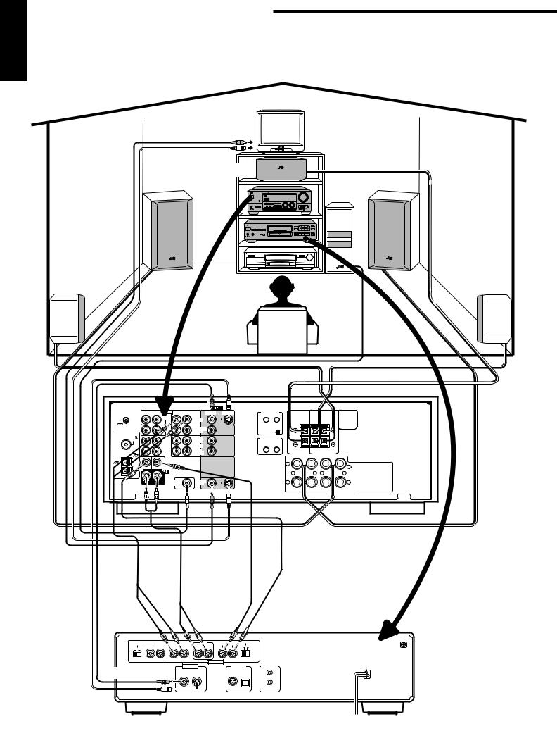
Easy Set Up & Operations
For Reproducing DVD MULTI playback with your DVD player
TV
To video input
To S-video input
Center Speaker
Front Speaker |
Front Speaker |
Rear Speaker |
Subwoofer |
Rear Speaker |
|
Speaker Signal Cable |
Speaker Signal Cable |
|
|
|
|
|
|
|
|
|
|
|
RX-774RBK |
Speaker Signal |
|
|
|
|
|
|
|
|
|
|
|
|
Cable |
|
RIGHT |
LEFT |
AUDIO RIGHT |
LEFT |
VIDEO |
S-VIDEO |
TEXT |
|
|
|
|
|
|
COMPU LINK |
CENTER |
|
REAR |
|
|
||||||
GND |
|
|
PHONO |
|
DVD |
|
|
SPEAKER |
SPEAKERS |
|
|
|
|
|
|
|
|
|
|
|
RIGHT |
LEFT |
|
|
|
|
|
|
|
|
|
|
|
|
|
|
||
|
|
|
CD |
|
TV SOUND |
|
1 (MASTER UNIT) |
|
|
|
|
|
ANTENNA |
|
|
/DBS |
|
2 (SLAVE UNIT) |
|
|
|
|
|
||
|
FM 75 |
|
OUT |
|
OUT |
|
COMPU LINK-3 |
|
|
|
|
|
|
COAXIAL |
|
|
|
(SYNCHRO) |
|
|
|
|
|
||
|
|
(REC) |
|
(REC) |
|
|
|
|
|
|
||
|
|
|
TAPE |
|
VCR |
|
|
|
|
|
|
|
|
|
|
/MD |
|
|
|
|
|
|
|
|
|
|
GND |
|
IN |
|
IN |
|
|
|
|
|
|
|
|
|
|
(PLAY) |
|
(PLAY) |
|
|
|
|
|
|
|
GND |
|
|
|
|
|
|
|
|
|
|
|
|
AM |
|
|
CENTER |
|
|
|
|
1 |
|
|
|
|
SUB |
|
|
|
|
|
|
|
|
1 |
|
||
LOOP |
|
DVD |
|
|
|
|
|
|
|
|
||
|
WOOFER |
|
|
|
|
|
|
+ |
– |
– |
+ |
|
|
AM |
|
|
|
|
|
|
|
||||
|
EXT |
|
|
|
|
|
|
|
|
|
|
|
|
|
|
SUBWOOFER |
|
MONITOR |
|
|
2 |
|
|
2 |
|
|
|
|
OUT |
|
OUT |
|
|
|
|
|
||
|
|
|
|
|
|
|
|
RIGHT |
|
|
LEFT |
|
|
|
|
|
|
|
|
|
|
|
|
FRONT SPEAKERS |
|
|
|
|
|
|
Speaker Signal |
Speaker Signal |
|
To rear |
|
|
Cable |
Cable |
|
|
|
|
|
|
||
|
left/right |
|
|
|
|
|
|
channel |
|
|
|
|
|
To front |
audio |
|
|
To center |
To subwoofer |
|
left/right |
output |
|
|
|||
|
channel |
audio output |
|
|||
channel |
|
|
|
|
||
|
|
|
audio |
|
|
|
audio |
|
|
|
|
|
|
|
|
|
output |
|
|
|
output |
|
|
|
DVD player |
|
|
|
|
|
|
|
|
|
ATTENUATOR |
2CH |
FRONT |
REAR |
CENTER SUBWOOFER |
|
1 |
|
RIGHT LEFT |
RIGHT LEFT |
RIGHT LEFT |
NORMAL |
GAIN PLUS |
|
OFF ON |
|
|||||
|
|
|
|
|
|
|
|
|
|
|
AUDIO OUT |
|
|
To video output |
VIDEO OUT |
DIGITAL OUT |
AV COMPU LINK |
|
||
|
|
PCM/DOLBY DIGITAL |
|
|
||
VIDEO |
S-VIDEO |
COAXIAL OPTICAL |
|
|
||
To S-video output
7
English
MASTER VOLUME
RX-774R AUDIO/VIDEO CONTROL RECEIVER
|
|
|
|
|
|
|
|
|
– |
+ |
STANDBY |
|
|
|
|
|
|
|
|
|
|
|
|
|
DOLBY SURROUND |
|
|
|
DVD |
CD |
|
|
|
|
|
|
|
|
|
|
TV SOUND/DBS |
PHONO |
|
|
|
|
EON |
TA/NEWS/INFO |
|
|
|
VCR |
TAPE/MD |
|
STANDBY/ON |
|
|
|
|
|
|
|
|
FM |
|
|
|
|
PTY SEARCH |
DISPLAY MODE |
|
|
|
|
|
|
POWER |
|
|
|
|
|
|
|
|
AM |
|
_ ON —OFF |
|
|
|
|
|
|
MULTI JOG |
SOURCE SELECTOR |
|
|
|
|
|
DSP MODE |
SEA MODE |
DVD MULTI/2CH |
FM/AM TUNING |
TUNER PRESET |
|
|
|
|
|
|
|
|
|
TUNER/SEA MEMORY |
FM MODE |
|
|
|
|
|
SPEAKERS |
BALANCE/SURROUND |
|
|
|
|
|
|
|
PHONES |
1 |
2 |
|
|
|
|
|
|
||
ADJUST |
SEA ADJUST |
SETTING |
|
|
|
|
|
|||
SOUND SELECT LOUDNESS ONETOUCHOPERATION
SOURCENAME
COMPULINK
Remote  ENHANCED COMPULINK CONTROL SYSTEM
2. Select the source.
|
|
|
|
CONTROL |
|
|
REMOTE |
AUDIO |
|
-SR774RU |
|
|||
|
SLEEP |
|||
RM |
VCR |
|
TV/DBS |
|
TV/CATV |
|
|
|
|
|
|
|
|
|
/DBS |
|
|
|
|
DVD |
MULTI |
|
|
|
CD |
|
SEA |
|
MODE |
|
|
|
CONTROL |
|
|
|
|
|
|
|
|
|
|
|
|
|
||
|
|
REMOTE |
|
|
AUDIO |
|
|
|
|
|
|
|
|
|
|
|
|
|
|
|
|
|
|
|
|
|
|
|
|
|
|
|
|
|
|
|
|
-SR774RU |
SLEEP |
|
|
|
|
|
|
|
|
|
|
|
|
|
|
|||
RM |
VCR |
|
|
TV/DBS |
|
|
|
|
|
|
|
|
|
|
||||
TV/CATV |
|
|
|
|
|
|
|
|
|
|
|
|
|
|||||
|
|
VCR |
|
|
|
|
|
|
|
|
|
|
|
|
|
|||
/DBS |
|
|
|
|
|
|
|
|
|
|
|
|
|
|
|
|
||
|
|
|
|
|
|
FM/AM |
|
|
|
|
|
|
|
|
|
|||
|
|
DVD |
|
|
|
|
|
|
|
|
|
|
|
|
|
|||
DVD |
MULTI |
|
|
PHONO |
|
|
|
|
MENU |
|
|
|
|
|
|
|
||
|
TAPE/MD |
|
CNTR |
3 |
|
|
|
|
|
|
|
|
||||||
|
|
|
|
|
|
|
|
|
|
|
||||||||
|
CD |
|
|
|
2 |
|
|
|
|
|
|
|
|
|
|
|||
|
|
TONE |
|
|
(L) |
|
|
|
|
|
|
|
|
|||||
|
|
|
|
|
|
|
|
|
|
|
|
|
||||||
|
|
CNTR |
|
REAR |
6 |
|
|
|
|
|
|
|
||||||
|
|
|
|
|
|
|
|
|
|
|
|
|||||||
|
SEA |
1 |
ENTER |
5 |
|
|
|
|
|
|
|
|
|
|||||
|
|
|
|
|
|
|
|
|
|
|
|
|||||||
|
MODE |
|
|
|
|
|
R) |
|
|
|
|
|
|
|
||||
|
TEST |
|
|
|
|
|
|
|
|
|
|
|
||||||
|
|
|
|
|
|
(REAR |
9 |
|
|
|
|
|
|
|||||
|
SURROUND |
|
4 |
|
|
|
|
|
|
|
|
|
||||||
|
|
|
|
|
|
|
|
|
|
|
|
|
|
|||||
|
|
MODE |
|
|
|
8 |
|
|
|
|
|
|
|
|
|
|||
|
|
|
EFFECT |
|
|
|
|
|
|
|
|
|
|
|||||
|
|
|
|
|
|
+10 |
|
|
|
|
|
|
||||||
|
|
SOUND |
|
7 |
|
|
|
|
|
|
|
|
|
|
|
|||
|
|
CONTROL |
|
/P |
|
|
|
0 |
|
|
|
|
|
|
|
|
||
|
|
|
DELAY |
|
|
|
|
100+ |
|
|
|
|
|
|
||||
|
|
|
|
|
|
|
|
MODE/MUTE |
|
|
|
|
|
|
|
|||
|
|
CD |
|
10 |
|
|
|
|
|
|
|
|
|
|||||
|
|
|
|
FM |
|
|
|
|
|
|
|
|
|
|||||
|
|
DISC |
RETURN |
|
|
|
|
|
|
|
|
|
|
|
||||
|
|
|
|
|
|
|
|
|
|
|
|
|
|
|
|
|||
|
|
AUDIO/TV |
VOLUME |
|
|
|
|
|
|
|
|
|
||||||
|
|
|
|
|
CHANNEL |
+ |
|
|
|
|
|
|||||||
|
|
|
/VCR |
|
|
|
|
|
|
|
|
|
||||||
|
|
|
|
|
|
|
|
|
|
|
|
|
PTY |
|
|
|
|
|
|
|
|
CATV |
|
|
|
|
|
|
|
|
/¢ |
|
|
|
|
||
|
|
|
|
|
|
|
|
|
|
|
FF |
|
|
|
|
|
||
|
|
|
|
/DBS |
MUTE |
|
|
|
|
SEARCH |
|
|
|
|
|
|
||
|
|
|
|
|
|
|
|
|
|
|
|
|
|
|
||||
|
|
|
|
|
|
|
|
|
|
PTY PLAY |
|
|
PAUSE |
|
|
|
|
|
|
|
|
|
|
|
|
– |
|
|
|
|
|
|
|
|
|
|
|
|
|
|
|
|
|
|
PTY/REW |
|
|
STOP |
|
|
|
|
|
|
||
|
|
|
|
|
|
|
4 |
|
|
|
|
|
VOLUME |
|
|
|
|
|
|
|
|
|
|
|
|
|
|
|
|
|
MODETV |
|
|
|
|
||
|
|
|
|
|
|
|
|
|
|
|
|
|
|
|
|
|
||
|
|
|
|
|
|
|
|
|
|
|
|
|
|
|
|
|
|
|
|
|
|
|
|
|
|
|
|
REC |
TV/VIDEO |
DISPLAY |
|
|
|
|
|
||
|
|
|
|
|
|
|
|
|
|
CONTROL |
|
|
EXIT |
|
||||
|
|
|
|
|
|
|
|
|
|
|
|
|
|
TAPE |
|
|
|
|
|
|
|
|
|
|
|
|
|
|
|
|
VCR |
|
|
|
|
|
|
|
|
|
|
|
|
|
|
|
|
|
SET |
|
|
|
|
|
|
|
|
|
|
|
|
|
|
|
|
|
|
|
|
|
|
|
|
R |
O |
|
|
|
|
|
|
|
|
|
|
|
|
|
|
|
|
|
|
|
|
|
|
|
|
|
|
|
|
|
|
|
|
|
|
|
|
T |
|
|
|
|
|
|
|
|
|
|
|
|
|
|
|
|
|
|
N |
|
|
|
|
|
|
|
|
|
|
|
|
|
|
|
|
|
MENU O |
|
|
|
|
|
|
|
|
|
|
|
|
|
|
|
|
|
|
|
C |
|
|
|
|
|
|
|
|
|
|
|
|
|
|
|
|
|
|
N |
|
|
|
|
|
|
|
|
|
|
|
|
|
|
|
|
|
E |
|
|
|
|
|
|
|
|
|
|
|
|
|
|
|
|
|
E |
|
|
|
|
|
|
|
|
|
|
|
|
|
|
|
|
ON SCR |
|
|
|
||
L
1. Turn on the power.
|
REMOTE |
CONTROLAUDIO |
|
|
|
|
|||||
|
|
|
|
|
|
|
|
|
|
||
-SR774RU |
SLEEP |
|
|
|
|
|
|
|
|
||
RM |
VCR |
|
|
|
TV/DBS |
|
|
|
|||
TV/CATV |
|
|
|
|
|
|
|||||
|
VCR |
|
|
|
|
|
|
||||
/DBS |
|
|
|
FM/AM |
|
|
|||||
|
DVD |
|
|
|
|
|
|
||||
DVD |
MULTI |
|
PHONO |
|
|
|
|
MENU |
|||
TAPE/MD |
|
|
CNTR |
3 |
|
||||||
|
|
|
|
||||||||
|
CD |
|
TONE |
2 |
|
|
(L) |
|
|||
|
|
|
|
|
|
||||||
|
|
CNTR |
|
REAR |
6 |
||||||
|
SEA |
|
1 |
|
ENTER |
5 |
|
|
|||
|
|
|
|
|
|
|
|||||
|
MODE |
|
|
|
|
|
|
R) |
|||
|
|
TEST |
|
(REAR |
|||||||
|
SURROUNDMODE |
4 |
|
|
|
9 |
|||||
|
|
|
8 |
|
|
||||||
|
|
|
EFFECT |
|
|
+10 |
|||||
|
SOUND |
|
|
/P |
|
|
|
|
|
||
|
|
7 |
|
|
|
0 |
|
||||
|
CONTROL |
|
DELAY |
|
|
|
100+ |
||||
|
|
CD |
|
10 |
|
|
MODE/MUTE |
||||
|
|
DISC |
|
|
FM |
|
|
||||
|
|
|
|
|
RETURN |
|
|
|
|
||
|
|
AUDIO/TV |
VOLUME |
|
NNEL |
||||||
|
|
|
/VCR |
|
|
|
|
|
|
|
|
|
|
|
|
|
|
|
|
|
|
HA |
|
3. Adjust the volume.
S MO |
|
|
CT |
8 |
|
|
|
EFFE |
|
+10 |
|
SOUND |
|
|
/P |
|
|
|
7 |
0 |
|
||
CONTROL |
|
DELAY |
100+ |
||
|
|
|
MODE/MUTE |
|
|
CD |
|
10 |
|
||
DISC |
FM |
|
|||
|
|
|
RETURN |
|
|
AUDIO/TV |
VOLUME |
|
|||
|
/VCR |
|
|
|
|
|
CATV |
|
|
|
|
|
|
/DBS |
MUTE |
|
|
|
|
|
PTY |
|
|
|
|
|
|
– |
|
|
|
|
|
PTY/REW |
|
|
|
|
|
4 |
|
|
|
|
|
REC |
|
|
|
|
|
TV/VIDEO |
|
4. DVD MULTI playback settings are preset at the factory.
However, if you need to make further adjustments, see pages 49 to 51.
M |
|
D |
P |
|
|
|
|
M |
|
|
DVD |
|
|
|
|
CNTR |
|
|
|||
|
TAPE/M |
|
|
3 |
||||||
|
|
|
|
|
|
|||||
|
CD |
|
TONE |
2 |
|
|
(L) |
|
||
|
|
CNTR |
|
|
6 |
|||||
|
|
|
|
REAR |
||||||
|
SEA |
1 |
|
ENTER |
5 |
|
|
|||
|
|
|
|
|
||||||
|
MODE |
|
|
|
|
|
R) |
|||
|
|
TEST |
|
(REAR |
||||||
|
SURROUNDMODE |
4 |
|
|
|
9 |
||||
|
|
|
8 |
|
|
|||||
|
SOUND |
EFFECT |
|
|
|
|||||
|
|
|
|
|
|
|
|
|
||
|
CONTROL |
|
|
|
|
|
|
|
||
|
|
CD |
|
|
|
|
|
|
|
|
|
|
DISC |
|
|
|
|
|
|
|
|
8

English

 Getting Started
This section explains how to connect audio/video components and speakers to the receiver, and how to connect the power supply.
Before Installation
General
•Be sure your hands are dry.
•Turn the power off to all components.
•Read the manuals supplied with the components you are going to connect.
Locations
•Install the receiver in a location that is level and protected from moisture.
•The temperature around the receiver must be between –5˚ and 35˚ C (23˚ and 95˚ F).
•Make sure there is good ventilation around the receiver. Poor ventilation could cause overheating and damage the receiver.
Handling the receiver
•Do not insert any metal object into the receiver.
•Do not disassemble the receiver or remove screws, covers, or cabinet.
•Do not expose the receiver to rain or moisture.
Checking the Supplied Accessories
Check to be sure you have all of the following items, which are supplied with the receiver.
The number in the parentheses indicates quantity of the pieces supplied.
•Remote Control (1)
•Batteries (2)
•AM (MW/LW) Loop Antenna (1)
•FM Antenna (1)
If anything is missing, contact your dealer immediately.
9
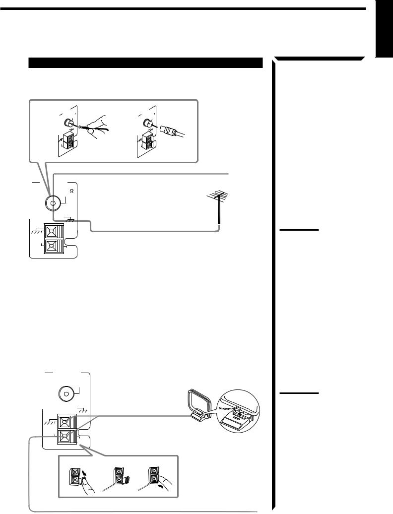
Connecting the FM and AM (MW/LW) Antennas
FM Antenna Connections
A |
ANTENNA 75 |
B |
ANTENNA |
75 |
|
FM |
|
|
FM |
|
COAXIAL |
|
|
COAXIAL |
|
GND |
|
|
GND |
GND |
|
|
GND |
|
AM |
|
|
AM |
|
LOOP |
AM |
|
LOOP |
AM |
|
EXT |
|
|
EXT |
|
|
FM Antenna |
|
|
ANTENNA |
Extend the supplied FM antenna horizontally. |
|||
|
|
|
||
FM 75 |
|
|
|
|
COAXIAL |
|
|
|
|
|
GND |
|
|
|
GND |
|
Outside FM Antenna Cable |
||
AM |
|
|
|
|
LOOP |
|
|
|
|
|
AM |
|
|
|
|
EXT |
|
|
|
A.Using the Supplied FM Antenna
The FM antenna provided can be connected to the FM 75Ω COAXIAL terminal as temporary measure.
B.Using the Standard Type Connector (Not Supplied)
A standard type connector (IEC or DIN45325) should be connected to the FM 75Ω
COAXIAL terminal.
AM (MW/LW) Antenna Connections
ANTENNA
FM 75
COAXIAL
GND
AM (MW/LW) Loop Antenna
GND
AM
LOOP
AM
EXT
1 2 3
Turn the loop until you have the best reception.
Snap the tabs on the loop into the slots of the base to assemble the AM (MW/ LW) loop.
Outdoor single vinylcovered wire
English
Note:
If reception is poor, connect the outside antenna.
Before attaching a 75Ω coaxial cable (the kind with a round wire going to an outside antenna), disconnect the supplied FM antenna.
Notes:
•Make sure the antenna conductors do not touch any other terminals, connecting cords and power cord. This could cause poor reception.
•If reception is poor, connect an outdoor single vinylcovered wire to the AM EXT terminal. (Keep the AM (MW/ LW) loop antenna connected.)
10
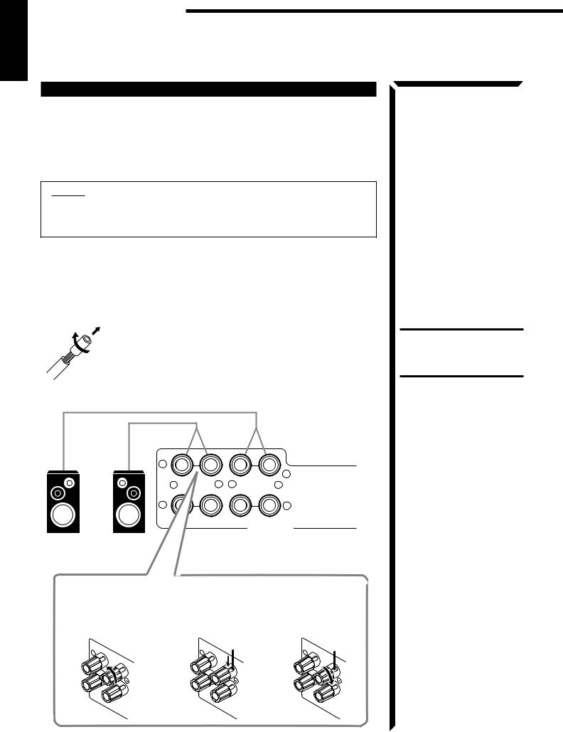
Getting Started
English
Connecting the Speakers
You can connect the following speakers:
•Two pairs of front speakers to produce normal stereo sound.
•One pair of rear speakers to enjoy the surround effect.
•One center speaker to produce more effective surround effect (to emphasize human voices).
•One subwoofer to enhance the bass.
IMPORTANT:
After connecting the speakers listed above, set the speaker setting information properly to obtain the best possible surround effect. For details, see page 24.
For each speaker (except for subwoofer), connect the (–) and (+) terminals on the rear panel to the (–) and (+) terminals marked on the speakers. For connecting a subwoofer, see page 12.
Connecting the front speakers
Cut, twist and remove the insulation at the end of each speaker signal cable first, and then, connect the front speakers to the FRONT SPEAKERS terminals by using the cables.
You can connect two pairs of front speakers (one pair to the FRONT SPEAKERS 1 terminals, and another pair to the FRONT SPEAKERS 2 terminals).
1 |
|
|
|
|
|
|
1 |
+ |
– |
– |
+ |
2 |
|
|
2 |
|
RIGHT |
|
LEFT |
FRONT SPEAKERS
Left Speaker Right Speaker
1 Turn the knob |
2 Insert the speaker |
3 Turn the knob |
counterclockwise. |
signal cable. |
clockwise. |
1 |
1 |
1 |
RIGHT |
RIGHT |
RIGHT |
CAUTION:
Use speakers with the SPEAKER IMPEDANCE indicated by the speaker terminals.
11
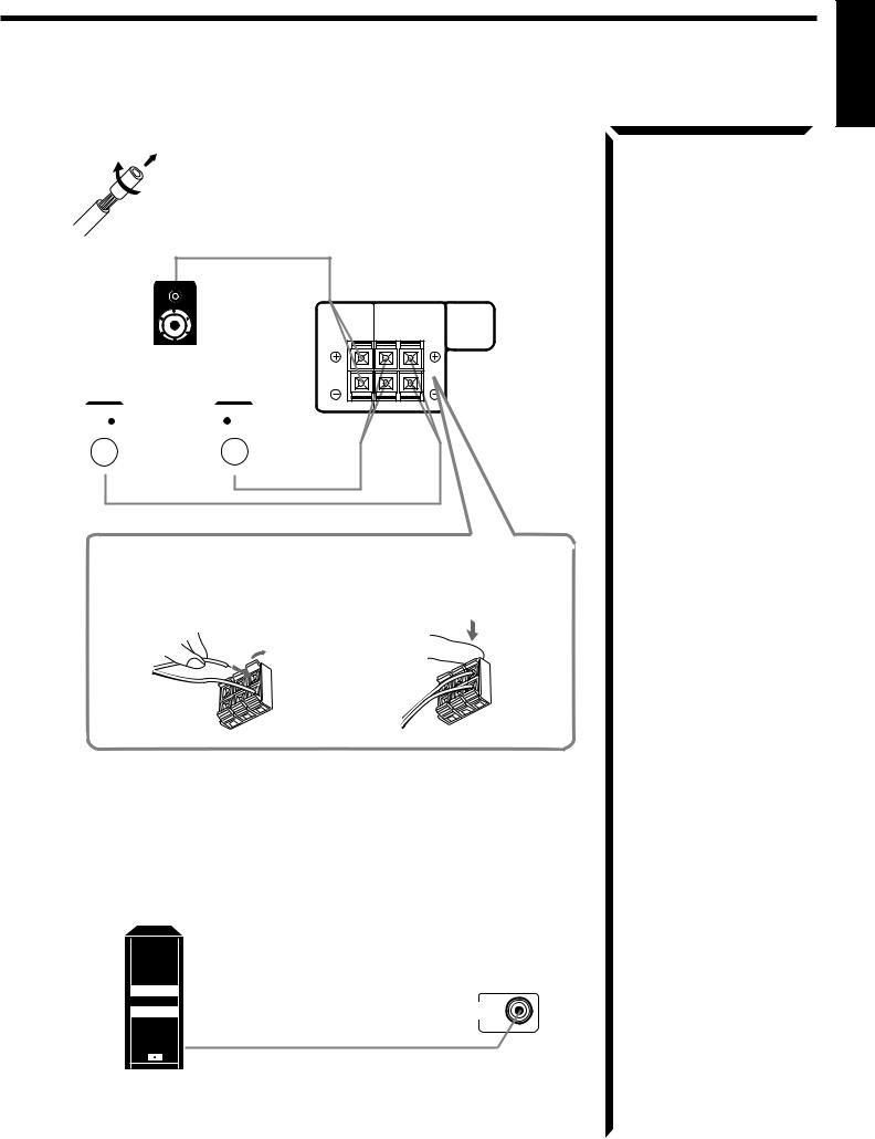
English
Connecting the rear and center speakers
Cut, twist and remove the insulation at the end of each speaker signal cable first, and then, connect rear speakers to the REAR SPEAKERS terminals and a center speaker to the CENTER SPEAKER terminals by using the cables.
Center speaker
Left rear speaker Right rear speaker
CENTER |
|
REAR |
SPEAKER |
SPEAKERS |
|
|
RIGHT |
LEFT |
|
|
|
|
|
1 Open the terminal and then |
2 Close the terminal. |
|||
insert the speaker signal |
|
|||
cable. |
|
|||
Connecting the subwoofer speaker
You can enhance the bass by connecting a subwoofer.
Connect the input jack of a powered subwoofer to the SUBWOOFER OUT jack on the rear panel, using a cable with RCA pin plugs.
SUBWOOFER
OUT
Powered subwoofer
12
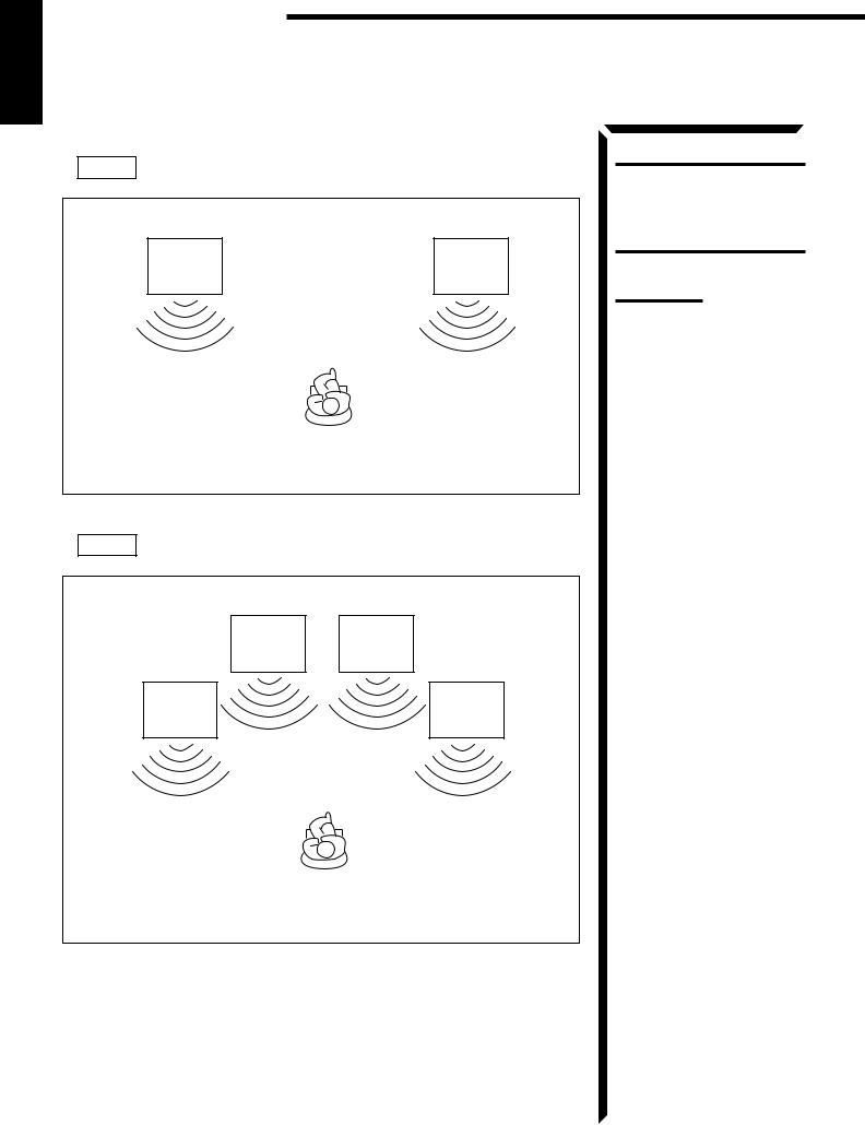
Getting Started
English
About the speaker impedance
CASE 1 When you connect only one set of front speakers
Front |
Front |
speaker |
speaker |
1 |
1 |
Use front speakers with 4 — 16 ohm impedance.
CASE 2 When you connect two sets of front speakers
Front |
Front |
speaker |
speaker |
2 |
2 |
Front |
Front |
speaker |
speaker |
1 |
1 |
Use front speakers with 8 — 16 ohm impedance.
CAUTION:
When connecting speakers, use speakers with the same SPEAKER IMPEDANCE indicated by the speaker terminals.
Note:
The required speaker impedance of the front speakers does differ depending on whether both the FRONT SPEAKERS 1 and FRONT SPEAKERS 2 terminals are used or only one of them is used.
13

Connecting Audio/Video Components
You can connect the following audio/video components to this receiver using cables with RCA pin plugs (not supplied). Refer also to the manuals supplied with your components. If you want to connect a component not listed in the table below, refer to the manual supplied with it.
Audio Components |
|
Video Components |
|
• Turntable |
• |
DVD (Digital Video Disc) player |
|
• CD player |
• TV |
||
|
|
|
|
• Cassette deck |
• |
DBS (Direct Broadcasting Satellite) tuner |
|
|
|
|
|
(or MD recorder) |
• VCR |
||
|
|
|
|
Audio component connections
Use the cables with RCA pin plugs (not supplied).
Connect the white plug to the audio left jack, and the red plug to the audio right jack.
Turntable
To audio output
English
CAUTION:
If you connect a soundenhancing device such as a graphic equalizer between the source components and this receiver, the sound output through this receiver may be distorted.
If an earth cable is provided for your turntable, connect the cable to the screw marked GND on the rear panel.
CD player |
RIGHT |
LEFT AUDIO RIGHT LEF |
|
GND |
PHONO |
||
|
To audio output |
|
|
|
|
CD |
|
|
|
OUT |
|
|
To audio input |
(REC) |
|
|
TAPE |
||
|
|
||
|
|
/MD |
|
|
To audio output |
IN |
|
|
(PLAY) |
||
Cassette deck |
|
CENTER |
|
SUB |
|
||
or |
DVD |
||
WOOFER |
|||
|
|
||
MD recorder |
To audio output |
|
|
|
|
||
|
|
SUBWOOFER |
|
|
To audio input |
OUT |
|
|
|
If your audio components have a COMPU LINK-3 or TEXT COMPU LINK terminal
•See also page 59 for detailed information about the connection and the COMPU LINK-3 remote control system.
•See also page 60 for detailed information about the connection and the TEXT COMPU LINK remote control system.
Notes:
•Any turntables incorporating a small-output cartridge such as an MC (moving-coil type) must be connected to this receiver through a commercial head amplifier or step-up transformer. Direct connection may result in insufficient volume.
•You can connect either a cassette deck or an MD recorder to the TAPE/MD jacks. When connecting an MD recorder to the TAPE/MD jacks, change the source name, which will be shown on the display when selected as the source, to “MD.” See page 23 for details.
14
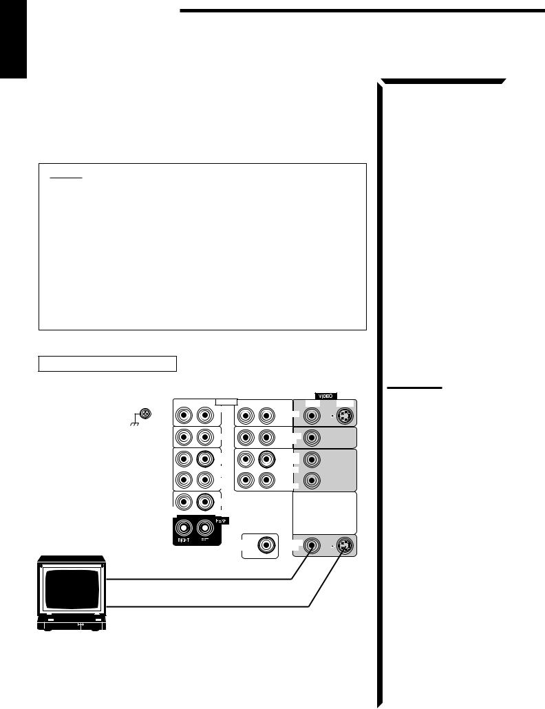
Getting Started
English
Video component connections
Use the cables with RCA pin plugs (not supplied).
Connect the white plug to the audio left jack, the red plug to the audio right jack, and the yellow plug to the video jack.
If DVD player and TV have S-video (Y/C-separation) terminals, connect them using S- video cables (not supplied). Connecting these video components through the S-video input/output terminals will give you better picture playback quality.
IMPORTANT:
This receiver is equipped with both the composite video and S-video input terminals for the DVD player connection.
You do not have to connect both the composite video and S-video terminals. However, remember that the video signals from the composite video input terminal are output only through the composite video output terminals, while the ones from the S-video input terminal are output only through the S-video output terminal.
Therefore, if your DVD player is connected to the receiver only through the S- video input terminal, you cannot record the picture from the DVD player on the VCR.
In addition, if the TV and the DVD player are connected to the receiver through the different video terminals, you cannot view the playback picture from the DVD player on the TV.
TV connection (as the monitor)
RIGHT |
LEFT |
AUDIO RIGHT |
LEFT |
VIDEO |
S-VIDEO |
GND |
|
PHONO |
|
DVD |
|
|
|
|
|
|
|
|
|
CD |
|
TV SOUND |
|
|
|
|
|
/DBS |
|
|
|
OUT |
|
OUT |
|
|
|
(REC) |
|
(REC) |
|
|
|
TAPE |
|
VCR |
|
|
|
/MD |
|
|
|
|
|
IN |
|
IN |
|
|
|
(PLAY) |
|
(PLAY) |
|
|
|
CENTER |
|
|
|
SUB |
|
DVD |
|
|
|
WOOFER |
|
|
|
|
|
TV (or Monitor) |
|
SUBWOOFER |
|
MONITOR |
|
|
OUT |
|
OUT |
|
To composite video input
To S-video input
(When the DVD player is connected using the S-video terminal)
Note:
Use the video components of the PAL color system.
15
English
DVD player connection
•When you connect the DVD player with stereo output jacks:
To S-video output (for better playback picture quality)
DVD player |
|
|
|
|
|
|
To front left/right channel audio output |
|
|
||||
(or to audio mixed output if necessary) |
|
|
||||
DVD |
|
|
|
|
|
|
RIGHT |
LEFT |
AUDIO |
RIGHT |
LEFT |
VIDEO |
S-VIDEO |
GND |
|
PHONO |
|
DVD |
|
|
|
|
|
|
|
|
|
To composite video output
|
CD |
TV SOUND |
|
|
/DBS |
|
OUT |
OUT |
|
(REC) |
(REC) |
|
TAPE |
VCR |
|
/MD |
|
|
IN |
IN |
|
(PLAY) |
(PLAY) |
|
CENTER |
|
SUB |
DVD |
|
WOOFER |
|
SUBWOOFER |
MONITOR |
OUT |
OUT |
• When you connect the DVD player with its analog discrete output (5.1 CH reproduction) jacks:
To S-video output (for better playback picture quality)
DVD player
DVD |
To front left/right channel audio output
RIGHT |
LEFT |
AUDIO RIGHT |
LEFT |
VIDEO |
S-VIDEO |
GND |
|
PHONO |
|
DVD |
|
|
|
|
|
|
To composite video output
To center channel audio output
To subwoofer audio output
To rear left/right channel audio output
|
CD |
TV SOUND |
|
|
/DBS |
|
OUT |
OUT |
|
(REC) |
(REC) |
|
TAPE |
VCR |
|
/MD |
|
|
IN |
IN |
|
(PLAY) |
(PLAY) |
|
CENTER |
|
SUB |
DVD |
|
WOOFER |
|
|
|
SUBWOOFER |
MONITOR |
|
OUT |
OUT |
16
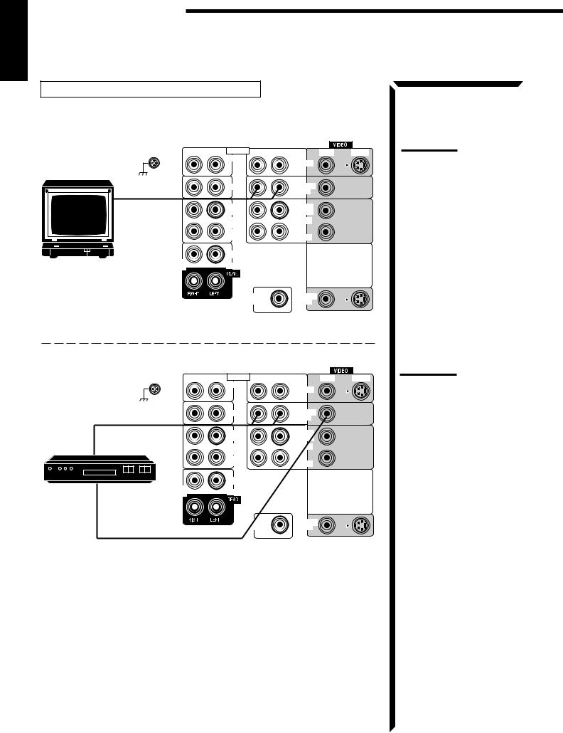
Getting Started
English
TV (as the sound source) or DBS tuner connection
You can connect either the TV or DBS tuner to the TV SOUND/DBS jacks.
TV
RIGHT |
LEFT AUDIO RIGHT LEFT |
|
Note: |
VIDEO |
S-VIDEO |
||
GND |
PHONO |
DVD |
When connecting the TV to the |
|
|
TV SOUND/DBS jacks, DO NOT |
|
|
|
|
|
|
|
|
connect the TV’s video output to |
|
CD |
TV SOUND |
the video input terminal of the |
|
|
/DBS |
|
To audio output |
|
|
TV SOUND/DBS jacks. |
OUT |
OUT |
|
|
|
(REC) |
(REC) |
|
|
TAPE |
VCR |
|
|
/MD |
|
|
|
IN |
IN |
|
|
(PLAY) |
(PLAY) |
|
|
CENTER |
|
|
SUB |
DVD |
|
|
WOOFER |
|
|
SUBWOOFER |
MONITOR |
OUT |
OUT |
RIGHT |
LEFT AUDIO RIGHT LEFT |
VIDEO |
S-VIDEO |
GND |
PHONO |
DVD |
|
|
|
|
|
To audio output |
CD |
TV SOUND |
|
|
/DBS |
|
|
|
OUT |
OUT |
|
|
(REC) |
(REC) |
|
DBS tuner |
TAPE |
VCR |
|
|
/MD |
|
|
|
IN |
IN |
|
|
(PLAY) |
(PLAY) |
|
DBS |
|
|
|
|
CENTER |
|
|
SUB |
DVD |
|
|
WOOFER |
|
|
|
|
SUBWOOFER |
MONITOR |
|
|
OUT |
OUT |
|
To video output
Note:
When connecting the DBS tuner to the TV SOUND/DBS jacks, change the source name, which will be shown on the display when selected as the source, to “DBS.” See page 23 for details.
17
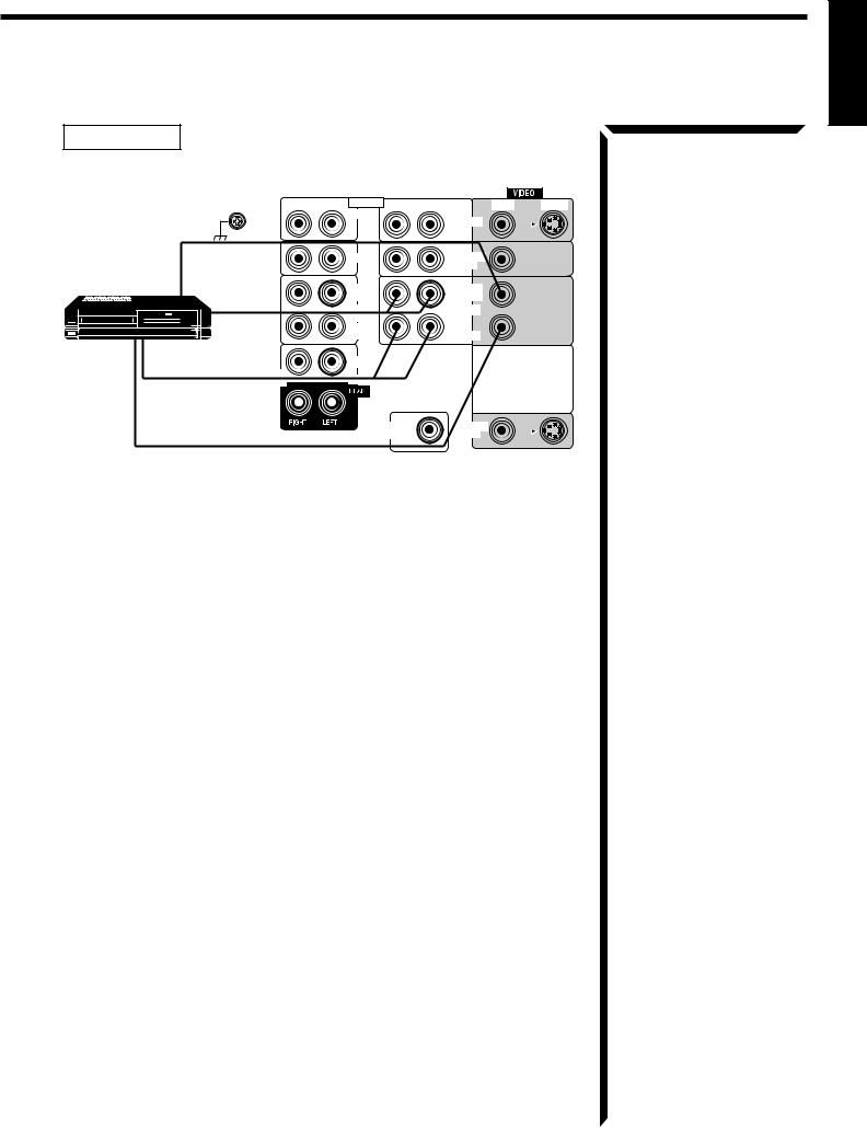
English
VCR connection
RIGHT |
LEFT |
AUDIO RIGHT |
LEFT |
VIDEO |
S-VIDEO |
GND |
|
PHONO |
|
DVD |
|
|
|
|
|
|
To video input |
CD |
TV SOUND |
|
|
/DBS |
VCR
VHS |
To audio |
|
|
|
input |
SUB
WOOFER
To audio output
OUT |
OUT |
(REC) |
(REC) |
TAPE |
VCR |
/MD |
|
IN |
IN |
(PLAY) |
(PLAY) |
CENTER |
|
DVD |
|
SUBWOOFER |
MONITOR |
OUT |
OUT |
To video output
18

Getting Started
English
Connecting the Power Cord
Before plugging the receiver into an AC outlet, make sure that all connections have been made.
1.Plug the power cord into an AC outlet.
2.Press  POWER to set it in the _ON position.
The STANDBY lamp lights up. A small amount of power is always consumed.
To shut off the power completely
Press  POWER to set it in the —OFF position.
 POWER
POWER
_ON
Keep the power cord away from the connecting cables and the antenna. The power cord may cause noise or screen interference. We recommend that you use a coaxial cable to connect the antenna, since it is well-shielded against interference.
The difference between the  POWER switch and the STANDBY/ON
  button
•The  POWER switch is the mains supply switch, allowing the receiver to connect to the mains supply. To shut off the power completely, press the
  POWER switch to set it in the —OFF position.
•The STANDBY/ON button is a functional on/off (standby) switch, and does not disconnect the receiver from the mains supply. A small amount of power is consumed even in standby mode for the receiver to accept signals from the remote control.
Note:
The preset settings such as preset channel and sound adjustment may be erased in the following cases:
–When you press  POWER to set it in the —OFF position.
–When you unplug the power cord.
–When a power failure occurs.
CAUTIONS:
•Do not touch the power cord with wet hands.
•Do not pull on the power cord to unplug the cord. When unplugging the cord, always grasp the plug so as not to damage the cord.
Putting Batteries in the Remote Control
Before using the remote control, put two supplied batteries first. When using the remote control, aim the remote control directly at the remote sensor on the receiver.
1.On the back of the remote control, remove the battery cover as illustrated.
2.Insert batteries. Make sure to observe the proper polarity: (+) to (+) and (–) to
(–).
3.Replace the cover.
R03 (UM-4)/AAA (24F)
- |
+ |
|
+ |
||
|
||
- |
|
If the range or effectiveness of the remote control decreases, replace the batteries. Use two R03 (UM-4)/AAA (24F) type dry-cell batteries.
CAUTION:
Follow these precautions to avoid leaking or cracking cells:
•Place batteries in the remote control so they match the polarity indicated: (+) to (+) and (–) to (–).
•Use the correct type of batteries. Batteries that look similar may differ in voltage.
•Always replace both batteries at the same time.
•Do not expose batteries to heat or flame.
19
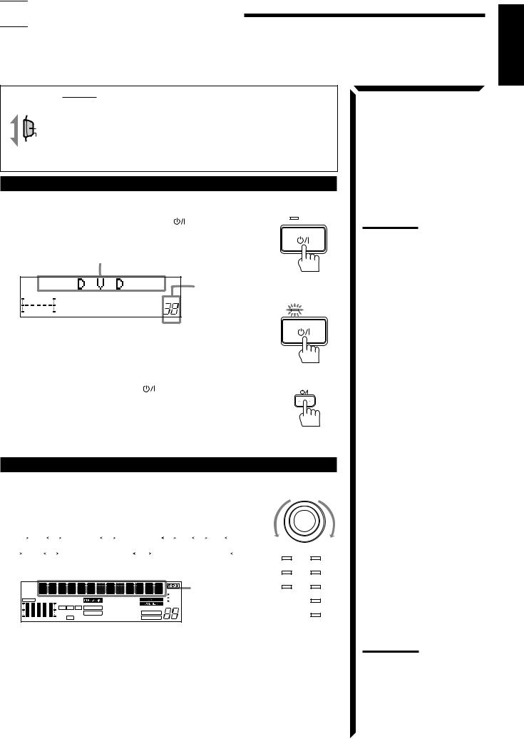

 Basic Operations
The following operations are commonly used when you play any sound source.
IMPORTANT:
When using the Remote Control, check to see if its remote control
AUDIO/TV mode selector is set to the correct position:
/VCR
|
To operate an audio system, TV, and VCR, set it to “AUDIO/TV/ |
|
|
/DBS |
VCR.” |
CATV |
|
To operate a CATV converter and DBS tuner, set it to “CATV/
DBS.”
Turning the Power On and Off (Standby)
On the front panel:
To turn on the power, press STANDBY/ON . |
STANDBY |
|
|
The STANDBY lamp goes off. The name of the current |
|
source (or station frequency) appears on the display. |
|
Current source name appears |
|
|
|
|
Current volume level is shown |
|
|
VOLUME |
here |
|
|
|
STANDBY |
100 |
1k |
10k |
|
To turn off the power (into standby mode), press
STANDBY/ON  again.
The STANDBY lamp lights up.
From the remote control:
To turn on the power, press AUDIO . |
AUDIO |
|
|
The STANDBY lamp goes off. The name of the current |
|
source (or station frequency) appears on the display. |
|
To turn off the power (into standby mode), press AUDIO  again. The STANDBY lamp lights up.
Selecting the Source to Play
On the front panel:
Turn SOURCE SELECTOR until the source name you |
SOURCE SELECTOR |
|||||||||||||||||||
|
|
|||||||||||||||||||
want appears on the display. |
|
|
|
|
|
|
|
|
|
|||||||||||
As you turn the selector, the source changes as follows: |
|
|
||||||||||||||||||
|
|
|
CD |
|
|
PHONO |
|
TAPE/MD |
|
FM |
|
AM |
|
|
|
|||||
|
|
|
|
|
|
|
|
|
|
|||||||||||
|
|
VCR |
|
|
|
TV SOUND/DBS |
|
|
DVD/DVD MULTI |
|
DVD |
CD |
||||||||
The selected source lamp also lights up. |
|
|
|
|
|
|
|
TV SOUND/DBS |
PHONO |
|||||||||||
|
|
|
|
|
|
|
|
|
VCR |
TAPE/MD |
CH– |
|
|
|
|
|
|
EON |
Selected source |
|
|
|
|
|
|
|
|
TA |
name appears |
FM |
||
|
|
|
|
|
|
|
|
|||
S E A |
FR CNTR |
|
|
|
THEATER |
DRAMA |
NEWS |
|
||
|
|
|
INFO |
|
||||||
|
|
L |
C |
R |
D S P |
LIVE CLUB |
ACTION |
VOLUME |
|
|
|
|
DANCE CLUB |
MUTE AUTO |
|
AM |
|||||
|
|
|
|
|
3D-PHONC |
HALL HEADPHONE |
LOUDNESS |
|
||
|
|
|
|
|
|
|
||||
100 |
1k |
10k |
S |
|
|
PAVILION |
|
SLEEP |
|
|
|
|
|
|
|
|
|
|
|||
For selecting DVD MULTI playback mode as the source:
Press DVD MULTI/2CH so that “DVD MULTI” appears on the display.
Each time you press the button, the DVD MULTI playback mode turns on and off, and the “DVD” and “DVD MULTI” alternately appears on the display.
•Select “DVD” when you play back a disc in stereo or the audio output setting of the DVD player is mixed to two front channels.
•Select “DVD MULTI” when you play back a disc on the DVD player with its analog discrete output mode (5.1 CH reproduction) selected. To enjoy the DVD MULTI playback mode, see page 49.
Note:
Pressing the STANDBY/ON  button again turns off the power (into standby mode) and lights the STANDBY lamp. A small amount of power is consumed in standby mode. To turn the power off completely, press the
  POWER switch to set it in the
—OFF position on the front panel.
Note:
When connecting an MD recorder (to the TAPE/MD jacks), and a DBS tuner (to the TV SOUND/DBS jacks), change the source name appears on the display. See page 23 for details.
English
20
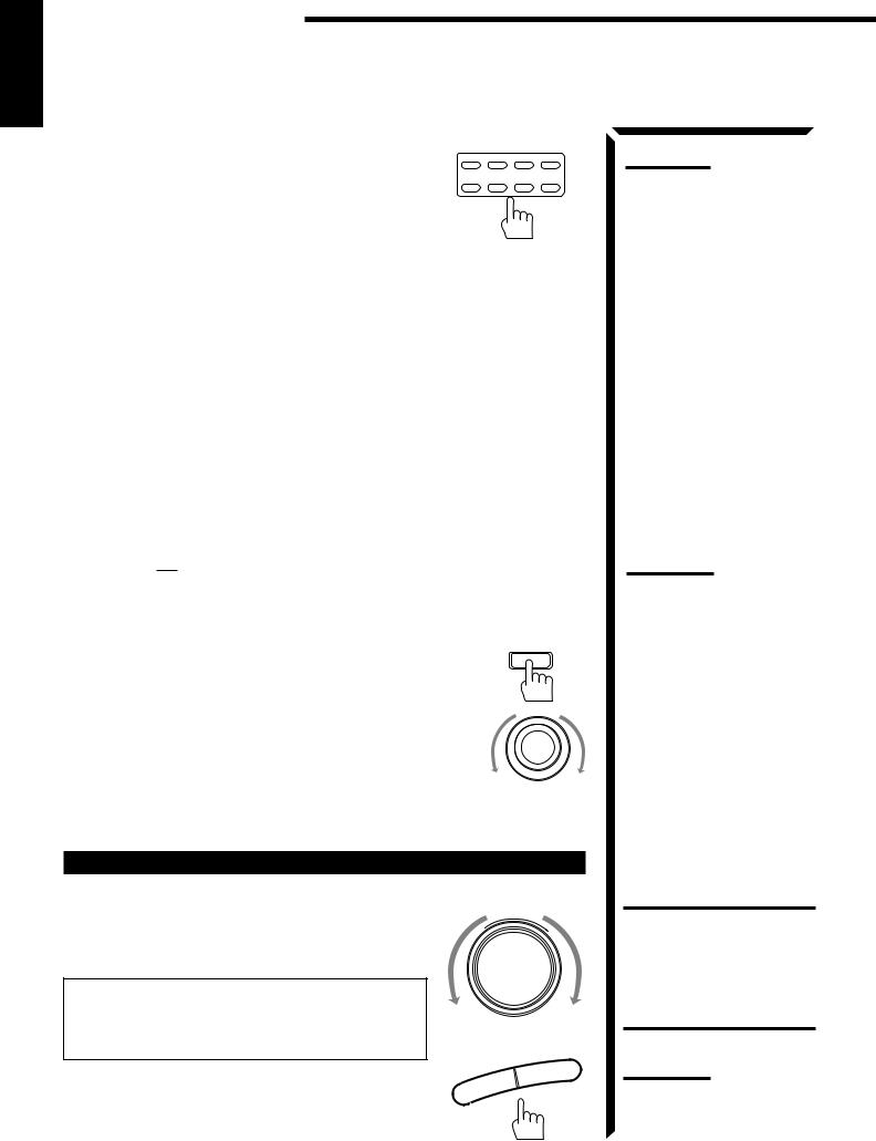
Basic Operations
English
From the remote control:
Press one of the source selecting buttons directly. |
DVD MULTI |
DVD VCR TV/DBS |
||
|
|
|
CD |
TAPE/MD PHONO FM/AM |
DVD MULTI |
Select the DVD player for viewing the |
|
|
|
|
digital video disc using the analog |
|
|
|
|
discrete output mode (5.1CH |
|
|
|
|
reproduction) on the DVD player. |
|
|
|
|
Each time you press the button, the source alternates between “DVD” |
|||
|
and “DVD MULTI.” |
|
|
|
DVD |
Select the DVD player for viewing the stereo digital video disc player. |
|||
|
(“DVD MULTI” will be selected when the last mode for the DVD |
|||
|
playback has been the DVD MULTI playback mode.) |
|
||
VCR |
Select the video component connected to the VCR jacks. |
|||
TV/DBS |
• |
Select the TV sound, when the remote control selector is set to |
||
|
|
“AUDIO/TV/VCR.” |
|
|
|
• |
Select the DBS tuner, when the remote control selector is set to |
||
|
|
“CATV/DBS.” |
|
|
CD* |
Select the CD player. |
|
|
|
TAPE/MD* |
Select the cassette deck (or the MD recorder). |
|
|
|
PHONO* |
Select the turntable. |
|
|
|
FM/AM* |
Select an FM or AM (MW/LW) broadcast. |
|
|
|
|
Each time you press the button, the band alternates between FM and |
|||
|
AM (MW/LW). |
|
|
|
Selecting different sources for picture and sound
You can watch picture from a video component while listening to sound from another component.
On the front panel: |
SOUND SELECT |
1.Press SOUND SELECT briefly while viewing the picture from a video component such as the VCR or DVD player, etc. “SOUND SELECT” appears on the display.
SOURCE SELECTOR
2.Turn SOURCE SELECTOR to select the sounds (except the TV sound), while the indication of the above step is still on the display.
From the remote control:
Press one of the audio source selecting buttons (CD, TAPE/MD, PHONO, FM/AM), while viewing the picture from a video component such as the VCR or DVD player, etc.
Adjusting the Volume
On the front panel:
To increase the volume, turn MASTER VOLUME clockwise.
To decrease the volume, turn it counterclockwise.
When you turn MASTER VOLUME rapidly, the volume level also changes rapidly.
When you turn MASTER VOLUME slowly, the volume level also changes slowly.
From the remote control:
MASTER VOLUME
–
+
VOLUME |
+ |
|
To increase the volume, press VOLUME +. |
– |
|
|
To decrease the volume, press VOLUME –. |
|
Note:
When you press one of the source selecting buttons marked above with an asterisk (*), the receiver automatically turns on.
Notes:
•Once you have selected a video source, pictures of the selected source are sent to the TV until you select another video source.
•When you select TV sound as the source, this function does not work.
CAUTION:
Always set the volume to the minimum before starting any source. If the volume is set at its high level, the sudden blast of sound energy can permanently damage your hearing and/or ruin your speakers.
Note:
The volume level can be adjusted within the range of “0” (minimum) to “90” (maximum).
21
 Loading...