


AUDIO / VIDEO CONTROL RECEIVER
RX-D702B
INSTRUCTIONS
LVT1437-009A
[UJ]
Warnings, Cautions, and Others
Caution–– STANDBY/ON button!
Disconnect the mains plug to shut the power off completely.
The  STANDBY/ON button in any position does not disconnect the mains line. The power can be remote controlled.
CAUTION
To reduce the risk of electrical shocks, fire, etc.:
1.Do not remove screws, covers or cabinet.
2.Do not expose this appliance to rain or moisture.
CAUTION
•Do not block the ventilation openings or holes.
(If the ventilation openings or holes are blocked by a newspaper or cloth, etc., the heat may not be able to get out.)
•Do not place any naked flame sources, such as lighted candles, on the apparatus.
•When discarding batteries, environmental problems must be considered and local rules or laws governing the disposal of these batteries must be followed strictly.
•Do not expose this apparatus to rain, moisture, dripping or splashing and that no objects filled with liquids such as vases, shall be placed on the apparatus.
CAUTION
Changes or modifications not approved by JVC could void the user’s authority to operate the equipment.
For U.S.A
This equipment has been tested and found to comply with the limits for a Class B digital device, pursuant to part 15 of the FCC Rules. These limits are designed to provide reasonable protection against harmful interference in a residential installation.
This equipment generates, uses and can radiate radio frequency energy and, if not installed and used in accordance with the instructions, may cause harmful interference to radio communications. However, there is no guarantee that interference will not occur in a particular installation. If this equipment does cause harmful interference to radio or television reception, which can be determined by turning the equipment off and on, the user is encouraged to try to correct the interference by one or more of the following measures:
-Reorient or relocate the receiving antenna.
-Increase the separation between the equipment and receiver.
-Connect the equipment into an outlet on a circuit different from that to which the receiver is connected.
-Consult the dealer or an experienced radio/TV technician for help.
For U.S.A
Declaration of Conformity:
Trade Name: |
JVC |
Model Number: |
RX-D702B |
This device complies with Part 15 of the FCC Rules. Operation is subject to the following two conditions:
(1)This device may not cause harmful interference.
(2)This device must accept any interference received,
including interference that may cause undesired operation. Responsible Party: JVC Americas Corp.
Address: 1700 Valley Road, Wayne New Jersey 07470
Telephone Number: 973-317-5000
For USB wireless transmitter
This device complies with Part 15 of the FCC Rules. Operation is subject to the following two conditions:
(1)This device may not cause harmful interference.
(2)This device must accept any interference received, including interference that may Cause undesired operation.
IMPORTANT NOTE:
FCC Radiation Exposure Statement:
This equipment complies with FCC RF radiation exposure limits set forth for an uncontrolled environment. To maintain compliance with FCC RF exposure compliance requirements, please avoid direct contact to the transmitting antenna during transmitting.
This transmitter must not be co-located or operating in conjunction with any other antenna or transmitter.
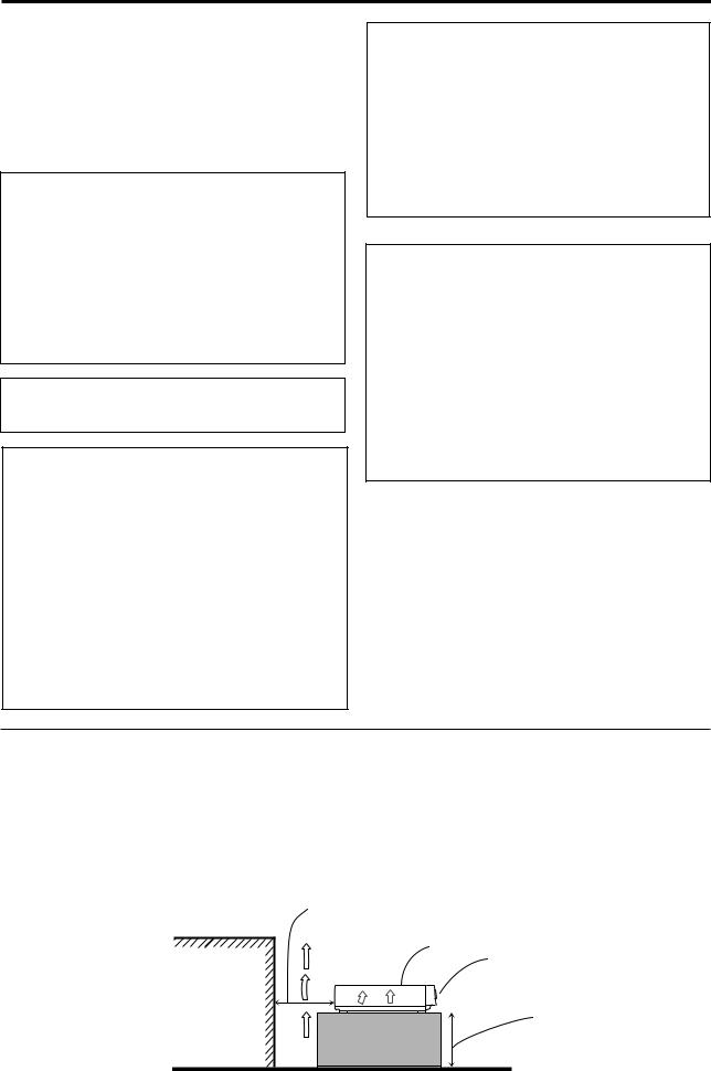
Caution: Proper Ventilation
To avoid risk of electric shock and fire and to protect from damage.
Locate the apparatus as follows:
Front: |
No obstructions open spacing. |
Sides: |
No obstructions in 15 cm from the sides. |
Top: |
No obstructions in 15 cm from the top. |
Back: |
No obstructions in 15 cm from the back. |
Bottom: |
No obstructions, place on the level surface. |
In addition, maintain the best possible air circulation as illustrated.
Spacing 15 cm or more
RX-D702B
Wall or obstructions
Front
Stand height 15 cm or more
Floor

Introduction
We would like to thank you for purchasing one of our JVC products.
Before operating this unit, read this manual carefully and thoroughly to obtain the best possible performance from your unit, and retain this manual for future reference.
Features
Hybrid Feedback Digital Amplifier
RX-D702B features the JVC-exclusive Hybrid Feedback Digital
Amplifier. Premium-grade parts and devices, and special internal construction assure you will enjoy superior sound.
USB WIRELESS
By using the USB wireless transmitter supplied with RX-D702B, sound reproduced from your PC can be transmitted to this receiver. You can choose PC as another playback source for
RX-D702B.
Compatible with HDMI*
The HDMI (High Definition Multimedia Interface) is the standard interface for the next-generation TV. By connecting the source components, this receiver, and TV with the HDMI cables, digital video signals and audio signals (including Dolby Digital, DTS) are transmitted through the cables. You can enjoy digital video and sound without AD/DA conversion with easy connection.
As RX-D702B supports up to HDMI version 1.1, this receiver can digitally transmit 5.1-channel PCM with sampling rates of 96 kHz and 2-channel PCM with sampling rates of 192 kHz.
(These PCM signals are referred to as “multi channel PCM” in this instruction.) You can enjoy digital sound without deterioration. In addition, this receiver is compatible with HDCP** (High-Bandwidth Digital Content Protection), and HDCP contents can be viewed if you connect a HDCPcompatible TV to this receiver.
*HDMI, the HDMI logo and High-Definition Multimedia
Interface are trademarks or registered trademarks of HDMI
Licensing LLC.
**HDCP is the abbreviation of “High-Bandwidth Digital Content
Protection,” and is the high-reliable copy control technology licenced by Digital Content Protection, LLC.
7.1 channel DAP (Digital Acoustic Processor)
Sound field simulation technology allows precise ambience recreation of existing theaters and halls. Thanks to the highperformance DSP (Digital Signal Processor) and high-capacity memory, you can enjoy 7.1-channel surround by playing 2- channel or multi-channel software.
K2 Technology
Precautions
Power sources
•When unplugging the receiver from the wall outlet, always pull the plug, not the AC power cord.
•Do not handle the AC power cord with wet hands.
•If you are not going to operate the receiver for an extended period of time, unplug the AC power cord from the wall outlet.
Ventilation
The seven high power amplifiers built in this receiver will generate heat inside the cabinet.
For safety, observe the following carefully:
•Make sure there is good ventilation around the receiver. Poor ventilation could overheat and damage the receiver.
•Do not block the ventilation openings or holes. (If the ventilation openings or holes are blocked by a newspaper or cloth, etc., the heat may not be able to get out.)
Others
•Should any metallic object or liquid fall onto the unit, unplug the unit and consult your dealer before operating any further.
•Do not use this receiver in a bathroom or places with water.
•Do not place any containers filled with water or liquids (such as cosmetics or medicines, flower vases, potted plants, cups, etc.) on top of this receiver.
•Do not disassemble the unit since there are no user serviceable parts inside.
If anything goes wrong, unplug the AC power cord and consult your JVC dealer.
K2 technology has been designed to enable natural audio reproduction, achieving a drastic reduction in digital distortion and creating original sound ambience with high precision.
CC(Compression Compensative) Converter
CCConverter eliminates jitter and ripples, achieving a drastic reduction in digital distortion by processing the digital music data in 24 bit–quantization and by expanding the sampling frequency to 128 kHz (for fs 32 kHz signals)/176.4 kHz (for fs 44.1 kHz signals)/192 kHz (for fs 48 kHz signals). By using the
CC Converter, you can obtain a natural sound field from any source.
DCDi technology
DCDi (Directional Correlational Deinterlacing) technology, developed by Faroudja, eliminates jagged edges generated in progressive scan conversion. With DCDi, you can enjoy clear and smooth video images on your display. For RX-D702B, this function is applied only when the NTSC analog video signals are transmitted to the receiver.
1

Table of Contents
Parts identification ................................................ |
3 |
Getting started ...................................................... |
6 |
Before Installation .................................................................. |
6 |
Checking the supplied accessories ....................................... |
6 |
Putting batteries in the remote control ................................... |
6 |
Setting the voltage selector ................................................... |
6 |
Connecting the FM and AM antennas ................................... |
7 |
Connecting the speakers ....................................................... |
8 |
Connecting video components .............................................. |
9 |
Connecting the power cord .................................................. |
16 |
USB connection ................................................................... |
17 |
Basic operations ................................................. |
19 |
1 Turn on the power ............................................................ |
19 |
2 Select the source to play .................................................. |
19 |
3 Adjust the volume ............................................................ |
20 |
Selecting the digital decode mode ....................................... |
21 |
Turning off the sounds temporarily ...................................... |
21 |
Changing the display brightness .......................................... |
21 |
Turning off the power with the Sleep Timer ......................... |
22 |
Making sounds natural ......................................................... |
22 |
Basic settings ...................................................... |
23 |
Setting the speaker information automatically |
|
—Smart Surround Setup ............................................... |
23 |
Basic setting items ............................................................... |
25 |
Operation through on-screen display menus ....................... |
25 |
Menu operation buttons ................................................... |
25 |
Setup menu configuration ............................................... |
26 |
Menu operating procedure ................................................... |
27 |
Setting the items .................................................................. |
28 |
Setting the speakers ....................................................... |
28 |
Activating the EX/ES/PLIIx setting—EX/ES/PLIIx ........... |
30 |
Selecting the main or sub channel—DUAL MONO ......... |
30 |
Setting bass sound .......................................................... |
30 |
Using the Midnight mode—MIDNIGHT ........................... |
31 |
Setting the digital input (DIGITAL IN) terminals |
|
—DIGITAL IN 1/2/3 ................................................... |
31 |
Setting the Audio delay level—AUDIO DELAY ................ |
31 |
Memorizing the volume level for each source |
|
—ONE TOUCH OP ................................................... |
32 |
Selecting the source for HDMI terminal and COMPONENT |
|
VIDEO jacks—HDMI SELECT/CMPNT SELECT ..... |
32 |
Selecting the output video signals—VIDEO OUTPUT .... |
32 |
Superimposing the menus—SUPERIMPOSE ................ |
32 |
Sound adjustments ............................................. |
33 |
Basic adjustment items ........................................................ |
33 |
Operation through on-screen display menus ....................... |
33 |
Menu operation buttons ................................................... |
33 |
Setup menu configuration ............................................... |
34 |
Menu operating procedure ................................................... |
35 |
Adjusting the items .............................................................. |
36 |
Adjusting the speaker output levels ................................. |
36 |
Adjusting the equalization patterns |
|
—DIGITAL EQ 63Hz/250Hz/1kHz/4kHz/16kHz ........ |
37 |
Adjusting the bass sounds .............................................. |
37 |
Adjusting the sound parameters for the |
|
Surround/DSP modes ............................................... |
37 |
Tuner operations ................................................. |
39 |
Setting the AM tuner interval spacing .................................. |
39 |
Tuning in to stations manually .............................................. |
39 |
Using preset tuning .............................................................. |
39 |
Selecting the FM reception mode ........................................ |
40 |
Creating realistic sound fields ........................... |
41 |
Reproducing theater ambience ........................................... |
41 |
Introducing the Surround modes ......................................... |
41 |
Introducing the DSP modes ................................................. |
43 |
Using the Surround/DSP modes ......................................... |
44 |
Activating the Surround/DSP modes ................................... |
45 |
AV COMPU LINK remote control system .......... |
46 |
Operating other JVC products ........................... |
48 |
Operating other manufacturers’ products ........ |
50 |
Troubleshooting .................................................. |
53 |
Specifications ...................................................... |
55 |
2
Parts identification
|
A/V CONTROL RECEIVER |
|
|||
|
REMOTE CONTROL RM-SRXD701U |
|
|||
|
TV/VIDEO |
|
|
AUDIO |
|
1 |
|
|
|
|
|
|
TV |
DBS/CATV |
VCR |
DVR/DVD |
|
2 |
|
|
|
|
|
|
TV |
DBS |
VCR |
DVR/DVD |
|
3 |
FM |
AM |
USB |
AUX |
|
4 |
TV VOL |
CHANNEL VOLUME |
i |
||
|
|
|
DVR |
|
|
|
|
|
|
|
o |
5 |
|
|
|
DVD |
|
|
|
|
MUTING |
|
|
|
|
|
|
; |
|
6 |
|
|
|
|
|
TUNING/REW |
|
FF/TUNING |
|
||
|
|
|
|||
7 |
SETTING |
|
|
DVD MENU |
|
|
|
|
|
a |
|
8 |
|
SET |
|
|
|
|
ADJUST |
|
|
EXIT |
|
9 |
|
|
|
|
s |
p |
VIDEO INPUT |
|
|
|
|
|
1 |
2 |
3 |
|
|
|
AUDIO INPUT |
|
|
|
|
q |
|
4 |
5 |
6 |
d |
w |
DECODE MODE |
|
|
||
|
7 |
8 |
9 |
|
|
e |
SURROUND |
RETURN |
FM MODE |
100 |
|
|
10 |
0 |
10 |
f |
|
r |
D.EQ FREQ CC CONVERTER MEMORY |
DIMMER |
|||
|
|
|
|
g |
|
|
|
C.TONE |
MIDNIGHT |
SLEEP |
|
|
|
h |
|||
|
|
|
|
|
|
|
D.EQ LEVEL |
EFFECT |
TEST SMART S.SETUP |
j |
|
t |
|
|
|
|
k |
|
|
|
|
l |
|
y |
|
|
|
|
|
L – FRONT – R |
CENTER |
SUBWFR |
|
||
|
|
||||
u |
|
|
|
|
|
|
L – SURR – R |
L – S. BACK – R |
|
||
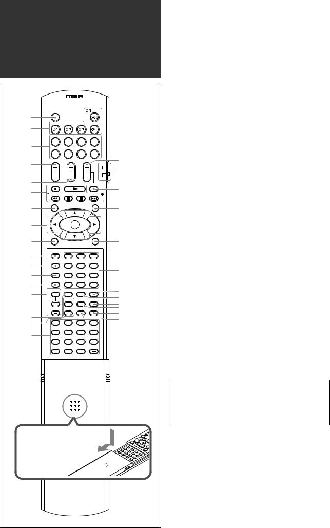
To open the cover of the remote control, push here then slide downward.
Remote control
See pages in parentheses for details.
1 TV/VIDEO button (48, 50)
2 Standby/on buttons (19, 48 – 52)
 AUDIO, TV
  , DBS/CATV
  , VCR
, VCR  , DVR/DVD
3 Source selecting buttons (19, 39, 48 – 52)
TV, DBS, VCR, DVR/DVD, FM, AM, USB, AUX 4 TV VOL (volume) +/– button (48, 50)
5 CHANNEL +/– button* (48 – 52)
6• Operating buttons for video components* (48, 49, 51, 52)
 , 3, REW, 4, 7, 8, FF, ¢
•Operating buttons for tuner (39)
( TUNING, TUNING 9 7 SETTING button (25, 27)
8 • Cursor buttons (3, 2, 5, ∞) (25, 27, 28, 33, 35, 49, 52)
• SET button (25, 28, 33, 35) 9 ADJUST button (33, 35)
p VIDEO INPUT button (20) q AUDIO INPUT button (20) w DECODE MODE button (21) e SURROUND button (45)
r Adjusting buttons for Digital Equalizer (37) D.EQ FREQ, D.EQ LEVEL +/–
t CC CONVERTER button (22)
y Adjusting buttons for Surround/DSP modes’ parameters C (center).TONE, EFFECT (37, 38)
uAdjusting buttons for speaker and subwoofer output levels (36)
FRONT L +/–, FRONT R +/–, CENTER +/–, SUBWFR +/–,
SURR L +/–, SURR R +/–, S.BACK L +/–, S.BACK R +/– i VOLUME +/– button (20)
o DVR/DVD mode selector* (49, 52) ; MUTING button (21)
a DVD MENU button* (49, 52) s EXIT button (25, 28, 33, 35)
d• Numeric buttons* (40, 48 – 52)
1– 10, 0, +10, 100+
•RETURN button (48)
•FM MODE button (40)
f DIMMER button (21)
g MEMORY button (39, 40) h SLEEP button (22)
j MIDNIGHT button (31)
k SMART S (surround). SETUP button (23, 24) l TEST button (36)
*These buttons can be used for operating a JVC DVD recorder or DVD player with the mode selector set to “DVR” or “DVD” (see page 49).
If these buttons do not function normally, use the remote control supplied with your DVD recorder or DVD player. Refer also to the manuals supplied with the DVD recorder or DVD player for details.
•When operating a DVD recorder (for JVC products ONLY), set the mode selector (o) to “DVR.”
•When operating a DVD player, set the mode selector (o) to “DVD.”
3

See pages in parentheses for details.
Front panel
1 |
2 3 4 5 |
6 7 |
8 |
9 |
p |
|
AUDIO/VIDE O |
CONTRO L |
STANDBY/ON |
CC CONVERTER |
SETTING |
RECEIVER
ADJUST |
SURROUND |
HDMI |
DVR / DVD |
VCR |
DBS |
TV |
USB |
FM/AM |
AUX |
SET / TUNER PRESET
SOURCE |
MASTER |
SELECTOR |
VOLUME |
/ MULTI JOG |
|
PUSH-OPEN
r |
t |
How to open the front door
PHONES |
USB |
DIGITAL |
S-VIDEO |
|
VIDEO |
L – AUDIO – R |
|||
|
|
|
AUX |
|
q |
w |
|
e |
|
Inside the front door
Press down on PUSH-OPEN.
1  STANDBY/ON button and standby lamp (19)
2 CC CONVERTER button (22)
3 SETTING button (25, 27)
4 ADJUST button (33, 35)
5 SURROUND button (45)
6 HDMI lamp (9, 20)
7Source lamps (19)
DVR/DVD, VCR, DBS, TV, USB, FM/AM, AUX
8• SET button (25, 28, 33, 35)
• TUNER PRESET button (40)
9• SOURCE SELECTOR (19, 40)
•MULTI JOG (25, 27, 28, 33, 35, 45) p MASTER VOLUME control (20)
q PHONES jack (20) w USB terminal (17) e AUX input jacks (15)
Digital optical terminal, S-video jack, VIDEO jack, AUDIO jacks
r Display window (5) t Remote sensor (6)
4
Display window |
|
|
|
|
|
|
|
|
|
|
|
||
1 2 3 4 5 6 |
7 |
|
8 9 0 - |
|
= ~ |
||||||||
ANALOG |
DUAL MONO |
AUTO SURR |
RDS |
NEWS INFO TUNED |
STEREO |
AUTO MUTING |
ONE TOUCH OPERATION |
SLEEP |
|||||
DIGITAL AUTO |
L |
C |
R |
HEADPHONE |
CC CONVERTER 1 2 |
AUTO MODE DIGITAL EQ C.TONE |
BOOST |
MIDNIGHT |
INPUT ATT |
||||
LINEAR PCM |
S.WFR |
LFE |
PL |
|
|
|
|
|
|
|
|
|
|
DIGITAL |
NEO : 6 DSP |
|
|
|
|
|
|
|
|
|
|||
LS |
S |
RS |
|
|
|
|
|
|
|
|
|
||
96 / 24 |
3D-PHONIC |
|
|
|
|
|
|
|
|
MHz |
|||
SB |
SB |
SB |
|
|
|
|
|
|
|
|
|||
|
VIRTUAL SB |
|
|
|
|
|
|
|
|
kHz |
|||
! @ # $ % ^ & |
* |
( ) |
_ |
1 ANALOG indicator (20)
2 DIGITAL and DIGITAL AUTO indicator (20, 21)
3 DUAL MONO indicator (30)
4 AUTO SURR (surround) indicator (45)
5 HEADPHONE indicator (20, 43)
6 CC CONVERTER 1 and CC CONVERTER 2 indicator (22)
7Tuner operation indicators (39) TUNED, STEREO
8 DIGITAL EQ indicator (37)
9 AUTO MUTING indicator (40)
0 C (center).TONE indicator (38)
- ONE TOUCH OPERATION indicator (32) = INPUT ATT (attenuate) indicator (37)
~ SLEEP indicator (22)
! Digital signal format indicators (20, 21, 41, 42) LINEAR PCM, 


 ,
,  , 96/24
@ Signal and speaker indicators (22)
# NEO:6 indicator (42)
$ VIRTUAL SB (surround back) indicator (44) % 3D-PHONIC indicator (42, 43)
^ DSP indicator (43)
& 

 and
and 

 indicator (41 – 43) * Main display
( B (bass).BOOST indicator (37) ) MIDNIGHT indicator (31)
_Frequency unit indicators
MHz (for FM stations), kHz (for AM stations)
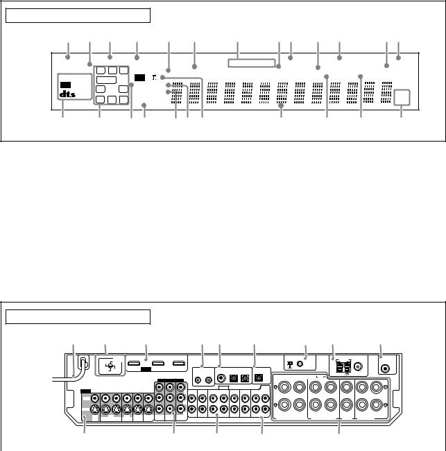
Rear panel
1 |
2 |
3 |
4 5 |
6 |
7 |
8 |
9 |
VIDEO
VIDEO
S-VIDEO
|
VOLTAGE |
VCR(DBS) IN |
DVR/DVD IN |
MONITOR OUT |
220V |
SELECTOR |
|||
110V |
|
|
|
|
230 - |
127V |
|
HDMI |
|
240V |
|
|
|
|
COMPONENT VIDEO
Y |
TV |
L IN |
PB
DBS |
VCR |
DVR |
DVR/DVD |
MONITOR |
|
|
PR R |
VCR(DBS) |
DVR/DVD |
MONITOR |
|||||
IN |
OUT(REC) IN(PLAY) |
OUT(REC) |
IN(PLAY) |
OUT |
IN |
IN |
OUT |
|
|
|
|
|
|
|
USB WIRELESS |
|
|
AM LOOP |
ANTENNA |
SUBWOOFER |
|
|
|
|
|
|
|
|
|
ANTENNA |
|
|
|
OUT |
|
AV |
|
DIGITAL IN |
|
DIGITAL OUT |
ON |
ID LEARNING |
|
|
|
|
|
||
|
|
|
|
|
|
|
FM 75 |
|
|||||
|
1(DVR/DVD) |
2(DBS) |
3(VCR) |
PCM/STREAM |
|
|
|
|
|
|
|||
COMPU LINK-III |
|
|
|
|
AM EXT |
|
|||||||
|
|
|
|
|
CAUTION:SPEAKER IMPEDANCE 6 |
-16 |
COAXIAL |
|
|||||
|
|
|
|
|
|
|
|
|
|
||||
|
|
AUDIO |
|
|
|
DVD |
|
|
|
|
|
|
|
DBS |
|
VCR |
DVR |
DVR/DVD |
|
MULTI IN |
|
|
|
|
|
|
|
|
|
SURR-L |
|
|
|
|
|
|
|
||||
IN |
OUT(REC) IN(PLAY) |
OUT(REC) |
IN(PLAY) |
CENTER |
|
|
|
|
|
|
|
||
|
|
|
|
FRONT |
SUBWOOFER |
|
RIGHT |
LEFT |
RIGHT |
LEFT |
|
RIGHT |
LEFT |
|
|
|
|
SURR-R |
|
|
|
|
CENTER |
|
|
||
|
|
|
|
|
|
|
SURROUND BACK SPEAKERS |
SURROUND SPEAKERS |
SPEAKER |
FRONT SPEAKERS |
|
||
|
p |
q |
w |
e |
r |
|
|
|
|
|
|
1 |
Power cord (16) |
|
|
p VIDEO jacks (10 – 14) |
|
2 |
VOLTAGE SELECTOR (6) |
|
|
VIDEO (composite video) jacks, S-VIDEO jacks |
|
3 |
HDMI terminals (10, 11, 13, 14) |
|
|
• Input: DBS IN, VCR IN (PLAY), DVR/DVD IN (PLAY) |
|
|
VCR(DBS) IN, DVR/DVD IN, MONITOR OUT |
|
|
• Output: VCR OUT (REC), DVR OUT (REC), MONITOR OUT |
|
4 |
AV COMPU LINK-III terminals (46) |
|
|
q COMPONENT VIDEO (Y, PB, PR) jacks (10 – 14) |
|
5 |
DIGITAL IN terminals (16) |
|
|
VCR(DBS) IN, DVR/DVD IN, MONITOR OUT |
|
|
• Coaxial: 1(DVR/DVD) |
|
|
w AUDIO jacks (10 – 14) |
|
|
• Optical: 2(DBS) |
|
|
• Input: TV IN, DBS IN, VCR IN (PLAY), DVR/DVD IN (PLAY) |
|
|
• Optical: 3(VCR) |
|
|
• Output: VCR OUT (REC), DVR OUT (REC) |
|
6 |
DIGITAL OUT terminal (16) |
|
|
e DVD MULTI IN jacks (12) |
|
7 |
• USB WIRELESS ANTENNA terminal (17) |
|
|
CENTER, SUBWOOFER, SURR – L, SURR – R |
|
|
• USB WIRELESS switch (17) |
|
|
r Speakers terminals (8) |
|
|
• USB WIRELESS lamp (17) |
|
|
SURROUND BACK SPEAKERS, SURROUND SPEAKERS, |
|
8 |
ANTENNA terminals (7) |
|
|
CENTER SPEAKER, FRONT SPEAKERS |
|
9 |
SUBWOOFER OUT jack (8) |
|
|
|
|
5
Getting started
Before Installation
General precautions
•Be sure your hands are dry.
•Turn the power off to all components.
•Read the manuals supplied with the components you are going to connect.
Locations
•Install the receiver in a location that is level and protected from moisture and dust.
•The temperature around the receiver must be between –5˚C and 35˚C.
•Make sure there is good ventilation around the receiver. Poor ventilation could cause overheating and damage the receiver.
•Leave sufficient distance between the receiver and the TV.
Handling the receiver
•Do not insert any metal object into the receiver.
•Do not disassemble the receiver or remove screws, covers, or cabinet.
•Do not expose the receiver to rain or moisture.
•Do not pull on the power cord to unplug the cord. When unplugging the cord, always grasp the plug so as not to damage the cord.
•When you are away on travel or otherwise for an extended period or time, remove the plug from the wall outlet. A small amount of power is always consumed while the power cord is connected to the wall outlet.
The receiver has a built-in cooling fan which operates while the receiver is turned on. Be sure to leave enough ventilation to obtain sufficient cooling effect.
CAUTION:
Do not connect the AC power plug to the wall outlet until all connections are completed.
Checking the supplied accessories
Check to be sure you have all of the following supplied accessories. If anything is missing, contact your dealer immediately.
•Remote control (× 1)
•Batteries (× 2)
•AM loop antenna (× 1)
•FM antenna (× 1)
•USB wireless antenna (× 1)
•USB wireless transmitter (Model number: QAL0708-001) (× 1)
•USB extension cable (60 cm) (× 1)
•AC plug adaptor (× 1)
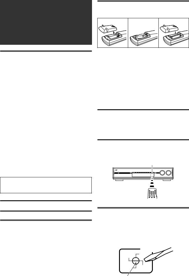
Putting batteries in the remote control
Before using the remote control, put two supplied batteries first.
1 |
2 |
3 |
1Press and slide the battery cover on the back of the remote control.
2Insert batteries.
Make sure to match the polarity: (+) to (+) and (–) to (–).
3 Replace the cover.
If the range or effectiveness of the remote control decreases, replace the batteries. Use two R6(SUM-3)/AA(15F) type dry-cell batteries.
•Supplied butteries are for initial setup. Replace for continued use.
CAUTION:
Follow these precautions to avoid leaking or cracking cells:
•Place batteries in the remote control so they match the polarity:
(+) to (+) and (–) to (–).
•Use the correct type of batteries. Batteries that look similar may differ in voltage.
•Always replace both batteries at the same time.
•Do not expose batteries to heat or flame.
When using the remote control, aim the remote control directly at the remote sensor on the front panel.
Remote sensor
Setting the voltage selector
Before connections, always do the following first if necessary.
Select the correct voltage in VOLTAGE SELECTOR on the rear of the receiver by using a screw driver.
•Check to be sure if the voltage mark is set to the voltage for your area where this unit plugs in.
VOLTAGE
SELECTOR
220V 110V
230 - |
127V |
|
240V |
||
|
Voltage mark
6
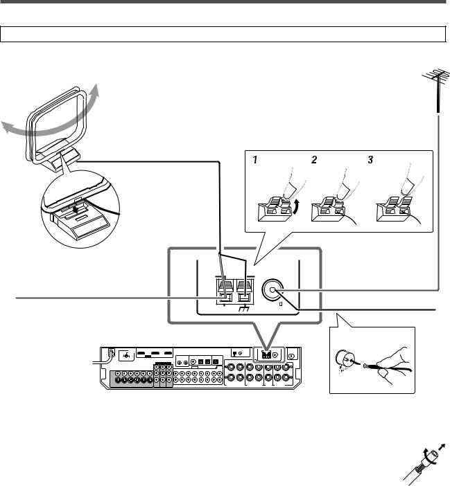
Connecting the FM and AM antennas
Do not connect the AC power plug to the wall outlet until all connections are completed.
AM loop antenna (supplied)
If FM reception is poor, connect an outdoor FM antenna (not supplied).
Snap the tabs on the loop into the slots of the base to assemble the AM loop antenna.
If AM reception is poor, connect an outdoor single vinyl-covered wire (not supplied).
220V 110V
230 -  127V
127V
240V
 AM LOOP
  ANTENNA
FM 75
AM EXT |
COAXIAL |
FM antenna (supplied)
ANTENNA
AM antenna connection |
|
|
|
|
|
|
|
|
|
|
|
|
|
|
|
|
|
|
|
|
|
|
|
|
|
|
|
|
|
|
|
|
|
|
|
|
NOTES |
Connect the AM loop antenna supplied to the AM LOOP terminals.
Connect the white cord to the AM EXT terminal, and connect the black cord to the H terminal.
Turn the loop until you have the best reception.
•If the reception is poor, connect an outdoor single vinyl-covered wire (not supplied) to the AM EXT terminal. Keep the AM loop antenna connected.
•If the AM loop antenna wire is covered with vinyl, remove the vinyl while twisting it as shown on the right.
•Make sure the antenna conductors do not touch any other terminals, connecting cords and power cord. This could cause poor reception.
FM antenna connection
Connect the FM antenna supplied to the FM 75 Ω COAXIAL terminal as a temporary measure.
Extend the supplied FM antenna horizontally.
•If the reception is poor, connect an outdoor FM antenna (not supplied). Before attaching a 75 Ω coaxial cable with a
connector, disconnect the supplied FM antenna.
7
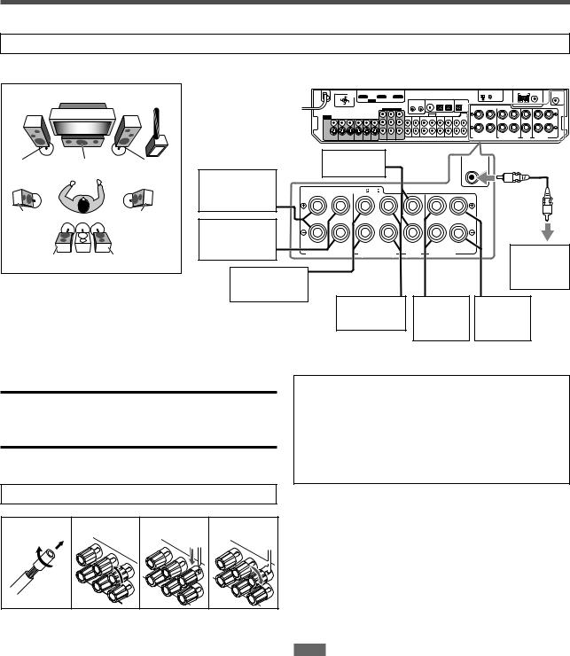
Connecting the speakers
Do not connect the AC power plug to the wall outlet until all connections are completed.
Speaker Layout Diagram
FL C
SL
SBL (*SB)
SW |
220V |
110V |
230 - |
127V |
|
240V |
|
|
|
|
|
FR |
|
Center |
|
|
||
|
|
speaker (C) |
|
SUBWOOFER |
|||
|
Right surround |
|
|
|
|||
|
|
|
|
|
|
|
|
|
back speaker |
CAUTION:SPEAKER IMPEDANCE 6 |
-16 |
|
|
||
|
(SBR) |
|
|
|
|
|
|
SR |
*Left surround |
|
|
|
|
|
|
|
|
|
|
|
|
|
|
|
back speaker |
RIGHT |
LEFT |
RIGHT |
LEFT |
RIGHT LEFT |
|
|
(SBL) |
|
|||||
SBR |
SURROUND BACK SPEAKERS |
|
|
CENTER |
Powered |
||
SURROUND SPEAKERS |
SPEAKER FRONT SPEAKERS |
||||||
|
Right surround |
|
|
|
|
subwoofer |
|
|
|
|
|
|
(SW) |
||
|
speaker (SR) |
|
|
|
|
|
|
|
|
|
|
|
|
|
|
|
|
|
Left surround |
Right front |
Left front |
||
|
|
|
speaker (SL) |
speaker |
speaker |
||
|
|
|
|
|
|
(FR) |
(FL) |
CAUTIONS:
•Use speakers with the SPEAKER IMPEDANCE indicated by the speaker terminals (6 Ω – 16 Ω).
•DO NOT connect more than one speaker to one speaker terminal.
Connecting the speakers
Turn off all components before making connections.
*When using a single speaker for the surround back speaker
You can enjoy the surround sound by one surround back speaker. When using one surround back speaker,
–set “S BACK OUT” to “S BACK OUT: 1SPK” (see page 29) and
–connect the surround back speaker to the left surround back speaker terminal. (No sound comes from the speaker if you connect it to the right surround back speaker terminal.)
Connecting the powered subwoofer
1 |
2 |
3 |
4 |
1Twist and remove the insulation at the end of each speaker cord.
By connecting a subwoofer, you can enhance the bass or reproduce the original LFE signals recorded in digital software.
Connect the input jack of a powered subwoofer to the SUBWOOFER OUT jack on the rear panel, using a cord with RCA pin plugs (not supplied).
• Refer also to the manual supplied with your subwoofer.
After connecting all the speakers and/or a subwoofer, set the speaker setting information properly to obtain the best possible surround effect. For details, see pages 23, 24, 28, and 29.
NOTE
2Turn the knob counterclockwise.
3Insert the speaker cord.
•For each speaker, connect the (+) and (–) terminals on the rear panel to the (+) and (–) terminals marked on the speakers.
4Turn the knob clockwise.
You can place a subwoofer wherever you like since bass sound is non-directional. Normally place it in front of you.
8
Connecting video components
Do not connect the AC power plug to the wall outlet until all connections are completed.
Video conversion function
This receiver can convert the video signals output from video components. The chart below shows which video signals can be converted into which signals by video conversion.
Video Input |
Converted |
Video Output |
|||
|
|
|
|
|
|
HDMI |
|
|
|
|
HDMI |
|
|
|
|
||
|
|
|
|
|
|
|
|
|
|
|
|
CMPNT (component) |
|
|
|
|
CMPNT (component) |
|
|
|
|
|
|
|
|
|
|
|
|
S (S-video) |
|
|
|
|
S (S-video) |
|
|
|
|
||
|
|
|
|
||
|
|
|
|
|
|
|
|
|
|
|
|
C (composite) |
|
|
|
|
C (composite) |
|
|
|
|
||
|
|
|
|
|
|
To use the video conversion function, you need to make the two settings below when you finish connecting your TV and video components.
VIDEO OUTPUT: Select the settings according to the connection method for your TV. See page 32 for details.
VIDEO INPUT: Select the settings according to the connection method for your video components. This setting is memorized for each source. See pages 11 to 15 and
20 for details.
Converted video signals available vary depending on each source component. See also pages 10 to 15 for details.
NOTES
•HDMI signals cannot be converted into other video signals.
•With input video signals converted into HDMI signals, the playback picture may be distorted when you change the playback mode (fast-forward, rewind, or pause, for example).
Before connecting video components
Before connecting video components, note the folllowing below.
IMPORTANT:
The HDMI video signals from the HDMI terminal are transmitted only through the HDMI MONITOR OUT terminal.
Therefore, if the TV is connected to the receiver through the VIDEO jack (MONITOR OUT), S-VIDEO jack (MONITOR OUT), or COMPONENT VIDEO jacks (MONITOR OUT) and a playing video component is connected to the receiver through the HDMI terminal
(VCR (DBS) IN or DVR/DVD IN), you cannot view the playback picture on the TV.
NOTES
•When playing back audio and video with the HDMI connection, the HDMI lamp on the front panel lights up.
•Set the audio input setting to “HDMI” when you enjoy sound with the HDMI connection. See “Selecting the audio input setting” on page
20.
•When connecting a VCR or DBS to HDMI VCR (DBS) IN terminal, select “HDMI SELECT” (see page 32) correctly according to the component you connect. If you do not, you cannot view the playback picture on the TV.
•By using a HDMI-DVI conversion cable, you can connect the source components or the TV with DVI output. When connecting those components or TV, change the audio input setting to the setting other than “HDMI.” (See page 20.)
•This receiver is compatible with standard video formats. If non-standard video formats are coming in, the picture may not appear properly on TV.
•The picture on the TV may not be the same aspect ratio as the ratio set on the source components.
•When connecting a TV to this receiver with an HDMI cable, the sound coming into this receiver is not transmitted to the speakers of the
TV. You can enjoy sound only from the speakers connected to this receiver.
•When connecting a TV to this receiver with an HDMI cable, turning a source component on or off, or changing the audio or video input setting of this receiver frequently may cause a noise or interrupt the sound and picture. In this case, turn the receiver off and turn it on again.
•When enjoying multi channel PCM sound with the audio input setting set to “HDMI” (see page 20), some functions are not available. See page 12 for details.
•When you enjoy HDCP contents, sound and picture may not be transmitted to the speakers and TV for a few seconds in the beginning for confirmation.
CAUTION:
If you connect a sound-enhancing device such as a graphic equalizer between the source components and this receiver, the sound output through this receiver may be distorted.
9
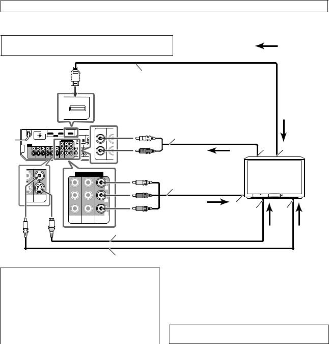
Do not connect the AC power plug to the wall outlet until all connections are completed.
7 Connecting a TV:
Connect the TV to the appropriate MONITOR OUT jacks to view the playback picture from any other connected video components.
Turn off all components before making connections.
: signal current
• When you connect other components, refer also to their manuals.
|
|
|
|
|
|
|
HDMI cable (not supplied) |
|
|
|
|
MONITOR OUT |
|
|
|
|
|
|
|
|
220V |
110V |
|
L |
TV |
DB |
White |
Stereo audio cable |
|
|
|
IN |
IN |
(not supplied) |
|
||||
|
|
|
|
|
|
|
|||
|
240V |
|
|
|
|
|
|
|
|
|
230 - |
127V |
|
|
|
|
|
|
|
|
|
|
|
|
|
|
Red |
Å |
ı TV |
|
|
|
|
|
|
|
|
||
|
|
|
|
R |
|
|
|
|
|
|
|
COMPONENT VIDEO |
|
Green |
Component video cable |
|
|||
|
|
|
|
|
|
||||
|
|
|
|
|
|
|
Blue |
(not supplied) |
|
|
|
|
|
|
Y |
|
|
|
|
|
|
|
|
|
|
|
|
|
|
/DVD |
MONITOR |
|
|
|
|
|
|
|
|
LAY) |
OUT |
|
|
PB |
|
Red |
|
|
|
|
|
|
|
|
|
Ç |
|
||
|
|
|
|
|
|
|
|
||
|
|
|
|
|
|
|
|
|
|
|
|
|
|
|
PR |
|
|
Î |
‰ |
|
|
VCR(DBS) DVR/DVD |
MONITOR |
|
|
|
|
||
|
|
IN |
IN |
|
OUT |
|
|
|
|
|
|
|
|
|
|
|
S-video cable (not supplied) |
|
|
Composite video cable (not supplied)
Select the appropriate VIDEO OUTPUT (see page 32) according to the terminal used for TV connection referring to the table below.
|
|
Connection method |
VIDEO OUTPUT |
|
|
|
|
HDMI |
HDMI |
|
|
|
|
Component video |
CMPNT |
|
|
|
|
S-video |
S |
|
|
|
|
Composite video |
C |
|
|
|
|
|
|
|
|
|
|
|
|
|
|
|
|
|
|
||
|
NOTES |
|
|
|
|
|
|
|
|
|
|
Å To left/right audio channel output ı To HDMI input
ÇTo component video input
•Connect Y, PB, and PR correctly. Î To S-video input
‰ To composite video input
DO NOT use a TV through a VCR or a TV with a built-in VCR; otherwise, the picture may be distorted.
•If connecting a TV only with the HDMI cable and setting the video input setting (see page 20) to “HDMI,” the on-screen display does not appear on the TV screen. When using on-screen display, set the video input setting to the setting other than HDMI.
•Select the audio and video input setting according to the connection method. See page 20 for details.
•In addition to using the HDMI cable, you can enjoy digital sound as well using a digital audio cable (coaxial or optical). For details of digital audio connection, see page 16.
•When you enjoy contents protected by HDCP (High-Bandwidth Digital Content Protection, see page 1), connect a HDCP-compatible TV to this receiver, otherwise, the picture may not appear properly.
10
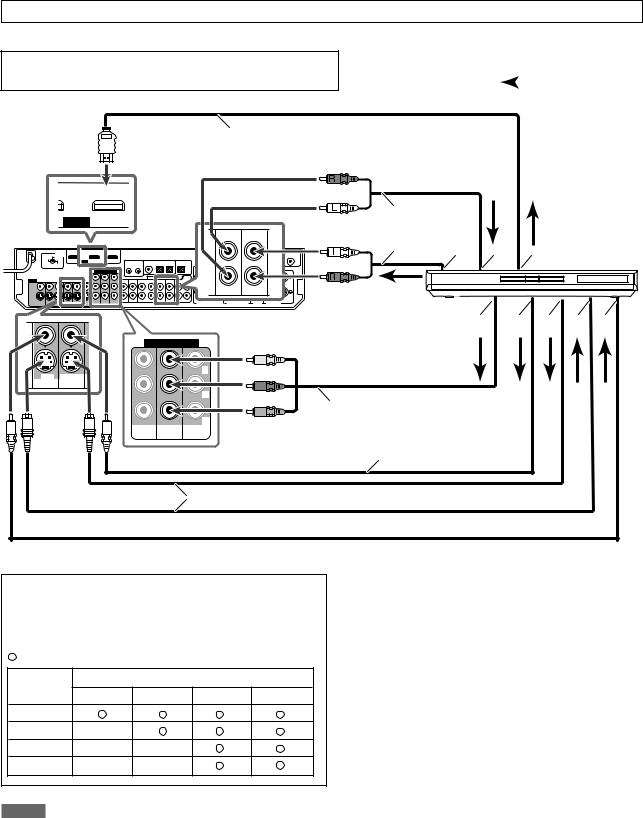
Do not connect the AC power plug to the wall outlet until all connections are completed.
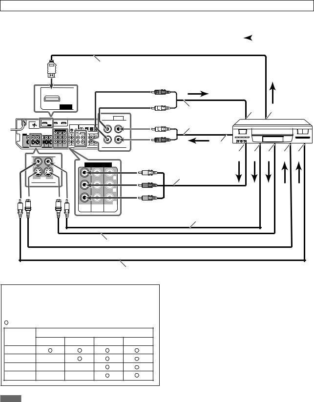
7 Connecting a DVD recorder or DVD player
Turn off all components before making connections.
• When you connect other components, refer also to their manuals. |
|
: signal current |
|
HDMI cable (not supplied)
Red
) IN |
DVR/DVD IN |
White
HDMI
220V 110V
230 -  127V
127V
240V
DVR DVR/DVD
OUT(REC) IN(PLAY)
|
Stereo audio cable |
|
White |
(not supplied) |
DVD recorder or |
|
||
|
Å ı |
|
Red |
Ç DVD player |
|
|
|
 FRONT
FRONT
|
COMPONENT VIDEO |
||
|
|
|
Y |
DVR |
DVR/DVD |
|
|
OUT(REC) |
IN(PLAY) |
|
|
|
|
|
PB |
|
|
|
PR |
|
VCR(DBS) |
DVR/DVD |
MONITOR |
|
IN |
IN |
OUT |
Î ‰ Ï Ì Ó
Green |
|
Blue |
|
Red |
Component video cable |
|
(not supplied) |
Composite video cable (not supplied)
S-video cable (not supplied)
 Composite video cable (not supplied)
Select the appropriate VIDEO INPUT (see page 20) according to the connection you have made. If you do not, you cannot view the playback picture on the TV.
Available video input setting for each video output setting:
: Available |
–: Not available |
|
|
|
VIDEO |
|
VIDEO INPUT |
|
|
OUTPUT |
HDMI |
CMPNT |
S |
C |
|
||||
HDMI |
|
|
|
|
CMPNT |
– |
|
|
|
S |
– |
– |
|
|
C |
– |
– |
|
|
Å To left/right audio channel output
ıOnly for DVD recorder: To left/right front channel audio input
Ç To HDMI output
ÎTo component video output
•Connect Y, PB, and PR correctly. ‰ To composite video output
Ï To S-video output
Ì Only for DVD recorder: To S-video input
Ó Only for DVD recorder: To composite video input
NOTES
•Select the audio and video input setting according to the connection method. See page 20 for details.
•In addition to using the HDMI cable, you can enjoy digital sound as well using a digital audio cable (coaxial or optical). When shipped from the factory, the digital coaxial terminal (DIGITAL IN 1 (DVR/DVD)) on the rear of the receiver is set for a DVD recorder and DVD player. For details of digital audio connection, see page 16.
•If your DVD recorder or DVD player is equipped with the analog multi channel output terminals, you can enjoy the sound recorded in DVD-Audio by connecting your DVD recorder or DVD player to DVD MULTI IN jacks. See page 12 for details.
When you enjoy the sound recorded in DVD-Audio with HDMI connection, see “When you enjoy sound recorded in DVD-Audio...” on page 12.
11

Do not connect the AC power plug to the wall outlet until all connections are completed.
When you connect a DVD recorder or DVD player with its analog discrete output jacks (DVD MULTI IN):
If your DVD recorder or DVD player has analog 5.1 channel output jacks, use the connection below. When a DVD Audio disc is played back, the original high-quality sounds can be reproduced by using this connection.
|
Turn off all components before making connections. |
|
|
• |
When you connect other components, refer also to their manuals. |
COMPONENT VIDEO |
Green |
: signal current |
|
||
|
|
|
Y |
Blue |
|
|
|
Component video cable (not supplied) |
|||
|
|
|
|
|
|
|
|
|
|
|
|
|
|
|
PB |
Red |
|
|
|
Monaural audio cable |
|
|
|
|
|
|
|
|
|
|
(not supplied) |
|
|
|
|
|
|
|
|
|
|
|
|
|
|
|
|
|
|
|
PR |
|
|
|
|
|
|
|
|
VCR(DBS) |
DVR/DVD |
MONITOR |
|
|
|
|
|
|
|
Ç |
|
IN |
IN |
OUT |
|
|
DVD |
|
Stereo audio cable |
|
|||
|
|
|
|
|
|
MULTI IN |
White |
|
|||
|
|
|
|
|
|
|
|
|
|||
|
|
|
|
|
CENTER |
SURR-L |
(not supplied) |
|
DVD recorder or |
||
|
|
|
|
|
|
|
|
ı |
|||
230 - |
127V |
|
|
|
|
|
Red |
|
Å |
DVD player |
|
220V |
110V |
|
|
|
|
|
|
|
|
|
|
240V |
|
|
|
|
|
|
|
|
|
|
|
|
|
|
|
|
SUBWOOFER |
SURR-R |
|
|
|
|
|
|
|
|
|
|
|
Monaural audio cable |
|
|
|
||
|
|
|
|
|
|
(not supplied) |
‰ Ï |
Ì Ó È Ô |
|||
|
|
|
|
|
|
|
|
|
|||
|
|
|
|
DVR |
DVR/DVD |
White |
|
Î |
|
|
|
|
|
|
|
OUT(REC) |
IN(PLAY) |
|
|
|
|
||
|
|
|
|
|
|
|
|
|
|
||
|
|
|
|
|
|
Red |
|
|
|
|
|
|
|
DVR |
DVR/DVD |
|
|
|
|
|
|
|
|
|
OUT(REC) |
IN(PLAY) |
|
|
|
|
Stereo audio cable |
|
|
||
|
|
|
|
|
FRONT |
Red |
|
|
|
||
|
|
|
|
|
|
|
(not supplied) |
|
|
|
|
|
|
|
|
|
|
White |
|
Composite video cable |
|
|
|
|
|
|
|
|
|
|
|
|
|
||
|
|
|
|
|
|
|
|
(not supplied) |
|
|
|
 S-video cable (not supplied)
Composite video cable (not supplied)
Å To left/right surround channel audio output |
Ï Only for DVD recorder: To left/right front channel |
ı To center channel audio output |
audio input |
Ç To component video output |
Ì To composite video output |
• Connect Y, PB, and PR correctly. |
Ó To S-video output |
Î To subwoofer output |
È Only for DVD recorder: To S-video input |
‰ To left/right front channel audio output |
Ô Only for DVD recorder: To composite video input |
When you enjoy sound recorded in DVD-Audio...
You can enjoy sound recorded in DVD-Audio both with analog or digital methods.
–With analog method:
•connect your DVD recorder or DVD player to this receiver according to the diagram above.
•select “A MULTI” in the audio input setting. (See page 20.)
–With digital method:
•connect your DVD recorder or DVD player and TV to this receiver with the HDMI cables. (See page 11.)
•select “HDMI” in the audio input setting. (See page 20.)
NOTES
•When selecting “A MULTI” in the audio input setting or when multi channel PCM signals (see page 42) are coming in with selecting “HDMI” in the audio input setting, you can listen to the front channel sounds (left and right) only by using the headphones. 3D HEADPHONE mode (see page 43) is not available.
•When selecting “A MULTI” in the audio input setting or when multi channel PCM signals (see page 42) are coming in with selecting “HDMI” in the audio input setting, the following items are not available:
–DECODE MODE (see page 21)
–CC Converter (see page 22)
–EX/ES/PLllx (see page 30)
–DUAL MONO (see page 30)
–SUBWFR OUT (see page 30)
–CROSSOVER (see page 31)
–LFE ATT (see page 31)
–MIDNIGHT (see page 31)
–AUDIO DELAY (see page 31)
–DIGITAL EQ 63Hz/250Hz/1kHz/4kHz/16kHz (see page 37)
–BASS BOOST (see page 37)
–INPUT ATT (see page 37)
–Sound parameters for Surround/DSP modes (see pages 37 and 38)
–Surround/DSP modes (see pages 41 to 45)
•When you enjoy sound recorded in DVD-Audio through the HDMI connection, use a DVD recorder or DVD player compatible with HDMI version 1.1.
12
Do not connect the AC power plug to the wall outlet until all connections are completed.
7 |
Connecting a VCR: |
|
|
|
Turn off all components before making connections. |
|
|
|
|
• |
When you connect other components, refer also to their manuals. |
|
|
: signal current |
|
||||
|
|
|
|
|
HDMI cable (not supplied)
|
|
VCR(DBS) IN |
|
|
|
HDMI |
|
|
|
|
AUDIO |
220V |
110V |
OUT(REC) |
VCR |
|
IN(PLAY) |
||
230 - |
127V |
|
|
240V |
|
|
|
COMPONENT VIDEO
VCR |
|
Y |
OUT(REC) IN(PLAY) |
|
|
|
|
PB |
|
|
PR |
VCR(DBS) |
DVR/DVD |
MONITOR |
IN |
IN |
OUT |
Red |
|
|
|
White |
|
|
|
|
Stereo audio cable |
Å |
ı VCR |
White |
(not supplied) |
|
|
|
|
|
|
Red |
|
|
|
|
Ç |
|
|
Î ‰ Ï Ì Ó
Green |
Component video cable |
Blue |
(not supplied) |
|
|
Red |
|
Composite video cable (not supplied)
 S-video cable (not supplied)
Composite video cable (not supplied)
Select the appropriate VIDEO INPUT (see page 20) according to the connection you have made. If you do not, you cannot view the playback picture on the TV.
Available video input setting for each video output setting:
: Available |
–: Not available |
|
|
|
VIDEO |
|
VIDEO INPUT |
|
|
OUTPUT |
HDMI |
CMPNT |
S |
C |
|
||||
HDMI |
|
|
|
|
CMPNT |
– |
|
|
|
S |
– |
– |
|
|
C |
– |
– |
|
|
Å To left/right audio channel input ı To HDMI output
Ç To left/right audio channel output
ÎTo component video output
•Connect Y, PB, and PR correctly. ‰ To composite video output
Ï To S-video output Ì To S-video input
Ó To composite video input
NOTES
•Select the audio and video input setting according to the connection method. See page 20 for details.
•In addition to using the HDMI cable, you can enjoy digital sound as well using a digital audio cable (coaxial or optical). When shipped from the factory, the digital optical terminal (DIGITAL IN 3 (VCR)) on the rear of the receiver is set for a VCR. For details of digital audio connection, see page 16.
•When connecting a VCR with a HDMI cable or component video cable, set “HDMI SELECT” or “CMPNT SELECT” to “VCR.” (see page 32)
13
Do not connect the AC power plug to the wall outlet until all connections are completed.
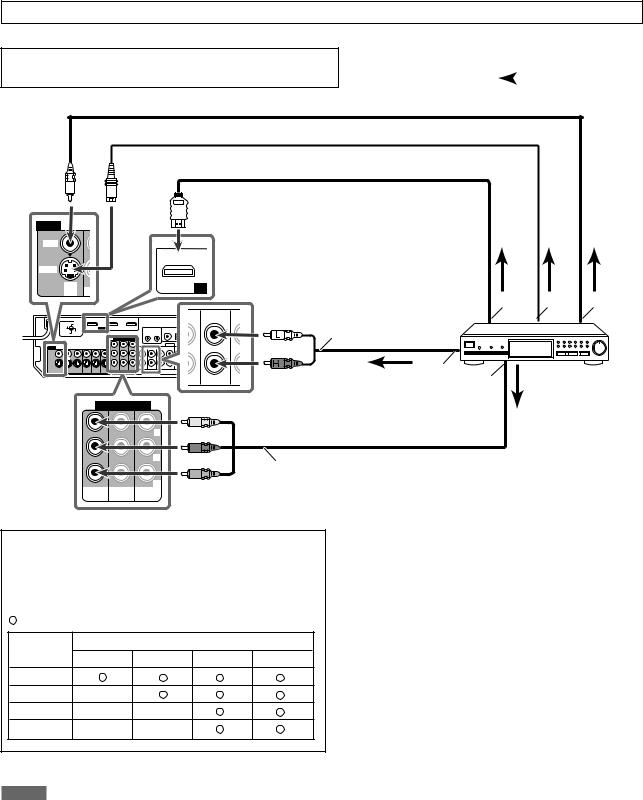
7 Connecting a DBS tuner:
Turn off all components before making connections.
• When you connect other components, refer also to their manuals. |
|
: signal current |
|
 Composite video cable (not supplied)
 S-video cable (not supplied)
 HDMI cable (not supplied)
VIDEO
VIDEO
|
|
VCR(DBS) IN |
S-VIDEO |
|
|
DBS |
O |
HD |
IN |
Å ı Ç
DBS |
OU |
White |
Stereo audio cable |
IN |
|||
|
|
|
(not supplied) |
|
|
Red |
|
Î |
DBS tuner |
|
‰ |
COMPONENT VIDEO
|
|
Y |
|
|
PB |
|
|
PR |
VCR(DBS) |
DVR/DVD |
MONITOR |
IN |
IN |
OUT |
Green
Blue
Red |
Component video cable (not supplied) |
Select the appropriate VIDEO INPUT (see page 20) according to the connection you have made. If you do not, you cannot view the playback picture on the TV.
Available video input setting for each video output setting:
: Available |
–: Not available |
|
|
|
VIDEO |
|
VIDEO INPUT |
|
|
OUTPUT |
HDMI |
CMPNT |
S |
C |
|
||||
HDMI |
|
|
|
|
CMPNT |
– |
|
|
|
S |
– |
– |
|
|
C |
– |
– |
|
|
NOTES
Å To HDMI output ı To S-video output
Ç To composite video output
Î To left/right audio channel output
‰To component video output
• Connect Y, PB, and PR correctly.
•Select the audio and video input setting according to the connection method. See page 20 for details.
•In addition to using the HDMI cable, you can enjoy digital sound as well using a digital audio cable (coaxial or optical). When shipped from the factory, the digital optical terminal (DIGITAL IN 2 (DBS)) on the rear of the receiver is set for a DBS tuner. For details of digital audio connection, see page 16.
•When connecting a DBS tuner with a HDMI cable or component video cable, set “HDMI SELECT” or “CMPNT SELECT” to “DBS.” (see page 32)
14

Do not connect the AC power plug to the wall outlet until all connections are completed.
7Connecting a video component to the AUX input jacks
The AUX input jacks on the front panel (inside the front door) are convenient when connecting and disconnecting the component frequently.
Before making connections, press PUSH-OPEN to show the jacks.
To enjoy the playback from the component connected to these jacks, select “AUX” as the source (see page 19).
How to open the front door |
Turn off all components before making connections. |
||
|
|
|
• When you connect other components, refer also to their manuals. |
|
|
|
|
|
|
|
|
DIGITAL |
S-VIDEO |
|
VIDEO |
L – AUDIO – R |
Red |
Stereo audio cable |
Video camera, etc. |
|
|
|
||
|
|
|
|
|
(not supplied) |
|
|
White |
Å |
|
|
|
|
Î |
|
|
|
ı Ç |
|
|
|
|
 Composite video cable (not supplied)
S-video cable (not supplied)
Digital optical cable (not supplied)
Select the appropriate VIDEO INPUT (see page 20) according to the connection you have made. If you do not, you cannot view the playback picture on the TV.
Available video input setting for each video output setting:
: Available |
–: Not available |
|
|
|
VIDEO |
|
VIDEO INPUT |
|
|
OUTPUT |
HDMI |
CMPNT |
S |
C |
|
||||
HDMI |
– |
– |
|
|
CMPNT |
– |
– |
|
|
S |
– |
– |
|
|
C |
– |
– |
|
|
: signal current
Å To left/right audio channel output ı To composite video output
Ç To S-video output
Î To digital optical output
NOTE
Select the audio and video input setting according to the connection method. See page 20 for details.
15
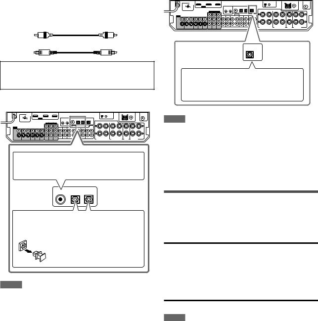
Digital audio connection
This receiver is equipped with three DIGITAL IN terminals—one digital coaxial terminal and two digital optical terminals—and one
DIGITAL OUT terminal on the rear of the receiver.
To reproduce the digital sound, use the digital audio connection in addition to the analog audio connection methods described on pages 10 to 15.
Digital coaxial cable (not supplied)
cable
Turn off all components before making connections.
•When you connect other components, refer also to their manuals.
7 Digital input terminals
220V 110V
230 -  127V
127V
240V
When the component has a digital coaxial output terminal, connect it to the 1(DVR/DVD) terminal, using a digital coaxial cable (not supplied).
DIGITAL IN
1(DVR/DVD) 2(DBS) 3(VCR)
When the component has a digital optical output terminal, connect it to the 2(DBS) or 3(VCR) terminal, using a digital optical cable (not supplied).
Before connecting a digital optical cable, unplug the protective plug.
NOTES
•When shipped from the factory, the DIGITAL IN terminals on the rear of the receiver have been set for use with the following components:
– 1(DVR/DVD): For DVD recorder or DVD player
– 2(DBS): |
For DBS tuner |
– 3(VCR): |
For VCR |
If you connect other components, change the digital input
(DIGITAL IN) terminal setting correctly. See “Setting the digital input (DIGITAL IN) terminals—DIGITAL IN 1/2/3” on page 31.
•Select the correct digital input mode. See “Selecting the audio input setting” on page 20.
7 Digital output terminal
You can connect any digital components which have an optical digital input terminal.
220V 110V
230 -  127V
127V
240V
DIGITAL OUT
PCM/STREAM
Connecting digital recording equipment to the
DIGITAL OUT terminal enables you to perform digital-to-digital recording.
NOTES
•The digital signal format transmitted through the DIGITAL OUT terminal is the same as that of the input signal. For example, when the DTS signals are coming, the DTS signals are transmitted.
•The digital audio signals coming through the following terminals cannot be transmitted through the DIGITAL OUT terminal:
–USB WIRELESS ANTENNA terminal
–USB terminal
–HDMI VCR(DBS) IN terminal and HDMI DVR/DVD IN terminal
Connecting the power cord
When all the audio/video connections have been made, connect the AC power plug to the wall outlet. Make sure that the plugs are inserted firmly. The standby lamp lights in red.
CAUTIONS:
•Do not plug in before setting the VOLTAGE SELECTOR switch on the rear of the receiver and all connection procedures are complete.
•Do not touch the power cord with wet hands.
•Do not alter, twist or pull the power cord, or put anything heavy on it, which may cause fire, electric shock, or other accidents.
•If the cord is damaged, consult a dealer and have the power cord replaced with a new one.
NOTES
•Keep the power cord away from the connecting cables and the antenna. The power cord may cause noise or screen interference.
•The preset settings such as preset channels and sound adjustment may be erased in a few days in the following cases:
–When you unplug the power cord.
–When a power failure occurs.
•If the wall outlet does not match the AC plug, use the supplied
AC plug adaptor.
•When you unplug the power cord with the receiver on and connect the power cord again, the receiver enters standby mode.
16
 Loading...