


 Loading...
HOME THEATER RECEIVER
RX-E100SL
POWER
DVD |
TV |
VCR |
AUDIO |
SLEEP |
TEST |
– SUBWOOFER + |
|
|
1 |
2 |
3 |
|
|
5 |
|
SURROUND |
EFFECT |
– CENTER + |
|
|
4 |
5 |
6 |
|
5 |
|
5 |
DSP MODE |
BASS |
– REAR•L + |
|
BOOST |
|||
|
7 |
8 |
9 |
SOUND |
|
5 |
MENU |
|
– REAR•R + |
||
|
10 |
0 |
+10 |
DVD |
|
|
ENTER |
TV |
VCR |
INPUT A/D |
|
TV/VIDEO |
CD |
FM |
AM |
MUTING
++
TV VOL |
VOLUME |
|
|
– |
|
– |
8 |
|
1 |
£ |
|
+ |
|
1 |
|
TV/VCR
CH
–
7
RM-SRXE100J
REMOTE CONTROL
HOME THEATER RECEIVER
STANDBY |
|
|
|
|
|
|
|
|
|
|
|
|
|
|
POWER |
TV DILECT |
|
|
|
|
|
|
RX-E100 |
HOME THEATER RECEIVER |
|
|
|
||
|
|
|
CONTROL |
ANALOG |
L |
C |
R |
PRO LOGIC SLEEP |
|
TUNED |
ST AUTO MUTING |
|
|
|
|
|
|
|
LPCM |
SUBWFR LFE DSP |
|
|
MH |
|
|
|
|||
|
|
|
|
DOLBY D |
LS |
S |
RS |
DGTL AUTO |
|
|
KH |
INPUT |
SURROUND |
DSP |
|
SETTING |
ADJUST |
|
DTS |
INPUT ATT |
|
|
VOL |
||||||
|
|
MEMORY |
|
|
|
|
|
|
|
ANALOG/DIGITAL |
ON/OFF |
MODE |
||
|
|
|
|
|
|
|
|
|
|
|
|
|
|
MASTER VOLUME |
|
|
|
|
|
|
|
|
|
|
|
|
INPUT ATT |
|
|
D I G I T A L |
|
|
|
DVD |
|
|
|
TV |
VCR |
CD |
FM |
AM |
|
|
|
|
|
|
|
|
|
|
|
||||||
S U R R O U N D |
D I G I T A L |
|
|
|
|
|
|
|
|
|
|
|
|
|
D I G I T A L
INSTRUCTIONS
For Customer Use:
Enter below the Model No. and Serial No. which are located either on the rear, bottom or side of the cabinet. Retain this information for future reference.
Model No.
Serial No.
LVT0650-001A
[J]

Warnings, Cautions and Others
|
|
CAUTION |
|
|
|
RISK OF ELECTRIC SHOCK |
|
|
|
DO NOT OPEN |
|
|
|
|
|
|
|
|
|
CAUTION: |
TO REDUCE THE RISK OF ELECTRIC SHOCK. |
||
|
DO NOT REMOVE COVER (OR BACK) |
||
|
NO USER SERVICEABLE PARTS INSIDE. |
||
REFER SERVICING TO QUALIFIED SERVICE PERSONNEL.
The lightning flash with arrowhead symbol, within an equilateral triangle is intended to alert the user to the presence of uninsulated "dangerous voltage" within the product's enclosure that may be of sufficient magnitude to constitute a risk of electric shock to persons.
The exclamation point within an equilateral triangle is intended to alert the user to the presence of important operating and maintenance (servicing) instructions in the literature accompanying the appliance.
WARNING: TO REDUCE THE RISK OF FIRE OR ELECTRIC SHOCK, DO NOT EXPOSE THIS APPLIANCE TO RAIN OR MOISTURE.
CAUTION
To reduce the risk of electrical shocks, fire, etc.:
1.Do not remove screws, covers or cabinet.
2.Do not expose this appliance to rain or moisture.
ATTENTION
Afin d’éviter tout risque d’électrocution, d’incendie, etc.:
1.Ne pas enlever les vis ni les panneaux et ne pas ouvrir le coffret de l’appareil.
2.Ne pas exposer l’appareil à la pluie ni à l’humidité.
Caution –– POWER switch!
Disconnect the mains plug to shut the power off completely. The
POWER switch in any position does not disconnect the mains line. The power can be remote controlled.
Attention –– Commutateur POWER!
Déconnecter la fiche de secteur pour couper complètement le courant. Le commutateur POWER ne coupe jamais complètement la ligne de secteur, quelle que soit sa position. Le courant peut être télécommandé.
Note to CATV system installer:
This reminder is provided to call the CATV system installer’s attention to Section 820-40 of the NEC which provides guidelines for proper grounding and, in particular, specifies that the cable ground shall be connected to the grounding system of the building, as close to the point of cable entry as practical.
For Canada/pour le Canada
CAUTION: TO PREVENT ELECTRIC SHOCK, MATCH WIDE BLADE OF PLUG TO WIDE SLOT, FULLY INSERT
ATTENTION: POUR EVITER LES CHOCS ELECTRIQUES, INTRODUIRE LA LAME LA PLUS LARGE DE LA FICHE DANS LA BORNE CORRESPONDANTE DE LA PRISE ET POUSSER JUSQUAU FOND
For U.S.A.
This equipment has been tested and found to comply with the limits for a Class B digital device, pursuant to part 15 of the FCC Rules. These limits are designed to provide reasonable protection against harmful interference in a residential installation.
This equipment generates, uses and can radiate radio frequency energy and, if not installed and used in accordance with the instructions, may cause harmful interference to radio communications. However, there is no guarantee that interference will not occur in a particular installation. If this equipment does cause harmful interference to radio or television reception, which can be determined by turning the equipment off and on, the user is encouraged to try to correct the interference by one or more of the following measures:
Reorient or relocate the receiving antenna.
Increase the separation between the equipment and receiver. Connect the equipment into an outlet on a circuit different from that to which the receiver is connected.
Consult the dealer or an experienced radio/TV technician for help.
For Canada/pour Le Canada
THIS DIGITAL APPARATUS DOES NOT EXCEED THE CLASS B LIMITS FOR RADIO NOISE EMISSIONS FROM DIGITAL
APPARATUS AS SET OUT IN THE INTERFERENCE-CAUSING
EQUIPMENT STANDARD ENTITLED “DIGITAL APPARATUS,” ICES-003 OF THE DEPARTMENT OF COMMUNICATIONS.
CET APPAREIL NUMERIQUE RESPECTE LES LIMITES DE
BRUITS RADIOELECTRIQUES APPLICABLES AUX APPAREILS NUMERIQUES DE CLASSE B PRESCRITES
DANS LA NORME SUR LE MATERIEL BROUILLEUR;
“APPAREILS NUMERIQUES”, NMB-003 EDICTEE PAR LE MINISTRE DES COMMUNICATIONS.
Caution: Proper Ventilation |
|
|
|
|
|
|
|
|
|
|
To avoid risk of electric shock and fire and to protect from damage. |
|
|
|
|
|
|
|
|
|
|
Locate the apparatus as follows: |
|
|
Spacing 15 cm or more |
|||||||
Front: |
No obstructions open spacing. |
|
|
|||||||
|
|
Dégagement de 15 cm ou plus |
||||||||
Sides: |
No obstructions in 10 cm from the sides. |
|
|
|
|
|
|
|
|
|
Top: |
No obstructions in 10 cm from the top. |
|
|
|
|
|
RX-E100SL |
|||
Back: |
No obstructions in 15 cm from the back |
Wall or obstructions |
|
|
|
|
|
Front |
||
Bottom: |
No obstructions, place on the level surface. |
Mur, ou obstruction |
|
|
|
|
|
|||
|
|
|
|
|
Avant |
|||||
|
|
|
|
|
|
|
||||
In addition, maintain the best possible air circulation as illustrated. |
|
|
|
|
|
|
|
|
|
|
Attention: Ventilation Correcte |
|
|
|
|
|
|
|
Stand height 15 |
||
|
|
|
|
|
|
|
||||
|
|
|
|
|
|
|
||||
|
|
|
|
|
|
|
||||
Pour éviter les chocs électriques, l’incendie et tout autre dégât. |
|
|
|
|
|
|
|
cm or more |
||
|
|
|
|
|
|
|
Hauteur du socle: |
|||
Disposer l’appareil en tenant compte des impératifs suivants |
|
|
|
|
|
|
|
|||
|
|
|
|
|
|
|
15 cm ou plus |
|||
Avant: |
Rien ne doit gêner le dégagement |
|
|
|
|
|
|
|
||
|
|
|
|
|
|
|
|
|
||
Flancs: |
Laisser 10 cm de dégagement latéral |
|
|
|
|
Floor |
||||
Dessus: |
Laisser 10 cm de dégagement supérieur |
|
|
|
|
|||||
|
|
|
|
Plancher |
||||||
Arrière: |
Laisser 15 cm de dégagement arrière |
|
|
|
|
|
|
|
|
|
Dessous: |
Rien ne doit obstruer par dessous; poser l’appareil sur une |
|
|
|
|
|
|
|
||
|
surface plate. |
|
|
|
|
|
|
|
|
|
Veiller également à ce que l’air circule le mieux possible comme illustré.

Table of Contents |
|
|
Getting Started........................................... |
2 |
|
Before Installation ...................................................................... |
2 |
|
Checking the Supplied Accessories ........................................... |
2 |
|
Putting Batteries in the Remote Control .................................... |
2 |
|
Connecting the FM and AM Antennas ....................................... |
3 |
|
Connecting the Speakers ............................................................ |
4 |
|
Connecting Audio/Video Components ....................................... |
6 |
|
Connecting the Power Cord ....................................................... |
6 |
|
Basic Operations ......................................... |
8 |
|
1 Turn On the Power ................................................................. |
8 |
|
2 Select the Source to Play ....................................................... |
8 |
|
3 Adjust the Volume .................................................................. |
8 |
|
Turning Off the Power with the Timer ....................................... |
9 |
|
Basic Settings........................................... |
10 |
|
Setting the Digital Input Terminals .......................................... |
10 |
|
Selecting the Analog or Digital Input Mode ............................ |
11 |
|
Setting the Subwoofer Information .......................................... |
12 |
|
Setting the Speakers for DSP Modes ....................................... |
12 |
|
Setting Auto Surround .............................................................. |
16 |
|
Sound Adjustments.................................... |
17 |
|
Attenuating the Input Signal .................................................... |
17 |
|
Adjusting the Front Speaker Output Balance ........................... |
17 |
|
Reinforcing the Bass ................................................................ |
18 |
|
Adjusting the Tone ................................................................... |
19 |
|
Adjusting the Subwoofer Output Level .................................... |
19 |
|
Tuner Operations ....................................... |
20 |
|
Tuning in Stations Manually .................................................... |
20 |
|
Using Preset Tuning ................................................................. |
20 |
|
Selecting the FM Reception Mode ........................................... |
21 |
|
Creating Realistic Sound Fields ................... |
22 |
|
About Relations between Speaker Layout and DSP Modes ....... |
24 |
|
Using Surround Modes (Remote Control) ............................... |
25 |
|
Using Theater Surround (Remote Control) .............................. |
26 |
|
Using DAP Modes (Remote Control) ...................................... |
28 |
|
Using Surround Modes (Front Panel) ...................................... |
29 |
|
Using Theater Surround (Front Panel) ..................................... |
30 |
|
Using DAP Modes (Front Panel) ............................................. |
31 |
|
Mastering Remote Operations .................... |
32 |
|
Parts Identification .................................... |
34 |
|
Troubleshooting ......................................... |
35 |
|
Specifications............................................ |
36 |
|
Memorandum ............................................ |
37 |
|
|
This mark indicates that the remote control CAN |
|
Remote |
ONLY be used for the operation explained. |
|
ONLY |
|
|
|
This mark indicates that only the remote control |
|
Remote |
CANNOT be used for the operation explained. |
|
NOT |
|
|
Contents of Others/Table and Cautions Warnings,
1
Getting Started
Before Installation |
Putting Batteries in the Remote Control |
General Precautions
•DO NOT insert any metal object into the receiver.
•DO NOT disassemble the receiver or remove screws, covers, or cabinet.
•DO NOT expose the receiver to rain or moisture.
Locations
•Install the receiver in a location that is level and protected from moisture.
•The temperature around the receiver must be between 23˚F and 95˚F (–5˚C and 35˚C).
•Make sure there is good ventilation around the receiver. Poor ventilation could cause overheating and damage the receiver.
Handling the receiver
•DO NOT touch the power cord with wet hands.
•DO NOT pull on the power cord to unplug the cord. When unplugging the cord, always grasp the plug so as not to damage the cord.
•Keep the power cord away from the connecting cords and the antenna. The power cord may cause noise or screen interference. It is recommended to use a coaxial cable for antenna connection, since it is well-shielded against interference.
•When a power failure occurs, or when you unplug the power cord, the preset settings such as preset FM/AM channels and sound adjustments may be erased in a few days.
Checking the Supplied Accessories
Check to be sure you have all of the following supplied accessories. The number in the parentheses indicates the quantity of the pieces supplied.
•Remote Control (1)
•Batteries (2)
•AM Loop Antenna (1)
•FM Antenna (1)
If anything is missing, contact your dealer immediately.
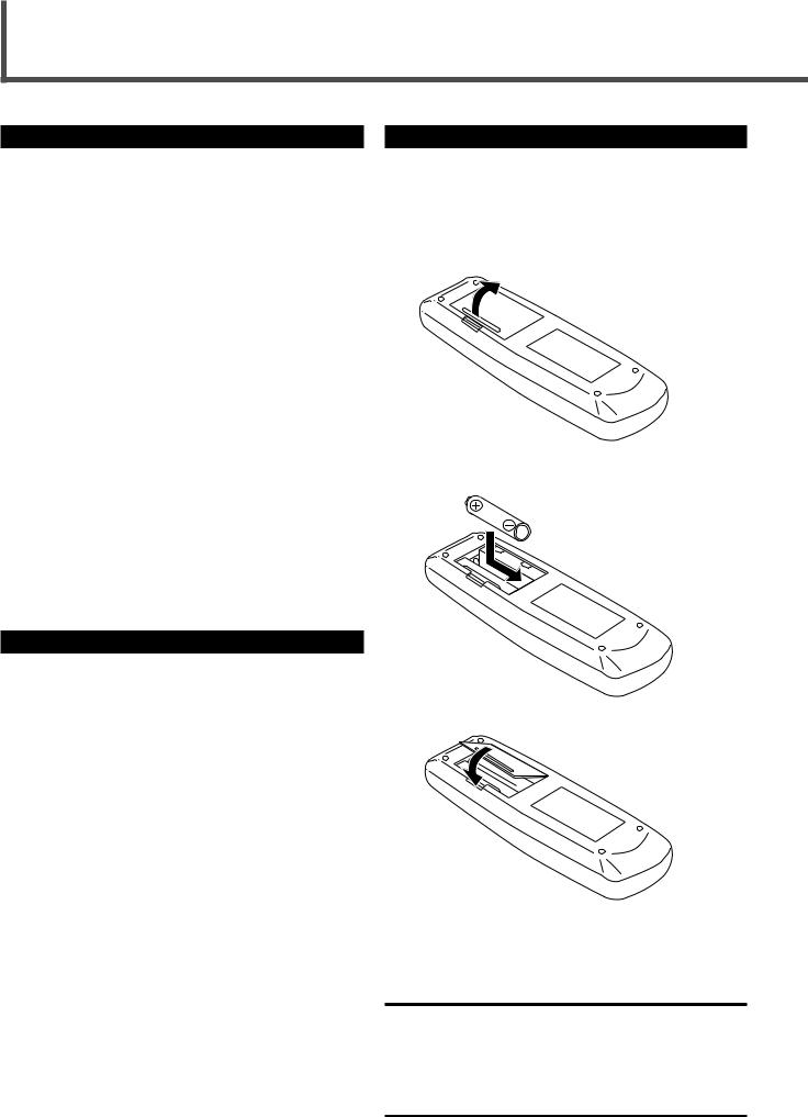
Before using the remote control, put two supplied batteries first.
• When using the remote control, aim the remote control directly at the remote sensor on the receiver.
1.On the back of the remote control, remove the battery cover.
2
1
2.Insert batteries. Make sure to match the polarity:
(+) to (+) and (–) to (–).
3. Replace the cover.
If the range or effectiveness of the remote control decreases, replace the batteries. Use two R6P(SUM-3)/AA(15F) type dry-cell batteries.
CAUTION:
Follow these precautions to avoid leaking or cracking cells:
•Place batteries in the remote control so they match the polarity: (+) to (+) and (–) to (–).
•Use the correct type of batteries. Batteries that look similar may differ in voltage.
•Always replace both batteries at the same time.
•Do not expose batteries to heat or flame.
2

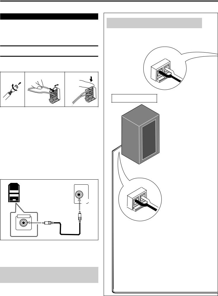
Connecting the FM and AM Antennas
AM Loop Antenna (supplied)
Snap the tabs on the loop into the slots of the base to assemble the AM loop antenna.
If AM reception is poor, connect single vinyl-covered wire (not supplied).
If FM reception is poor, connect outdoor FM antenna (not supplied).
B
FM |
75 |
L |
|
|
IA |
||
AX |
|
|
|
CO |
|
|
|
75
FMCOAXIAL
AM LOOP
FM Antenna (supplied)
AM |
FM 75 |
EXT |
COAXIAL |
|
ANTENNA |
1
2
3
Notes:
•If the AM loop antenna wire is covered with vinyl, remove the vinyl while twisting it as shown to the right.
•Make sure the antenna conductors do not touch any other terminals, connecting cords and power cord. This could cause poor reception.
|
|
IN |
1 |
SPEAKERS |
|
: |
|
DIGITAL |
LEFT |
+ |
CAUTION |
||
|
DIGITALV |
RIGHT |
||||
|
|
(D |
) |
FRONT |
|
SPEAKER |
|
|
|
SPEAKERS |
|
|
IMPEDANCE6 |
|
|
|
|
|
1 |
|
|
|
REAR |
LEFT |
+ |
– |
8 |
2 |
|
|
||||
CENTER |
RIGHT |
+ |
|
|
|
|
DIGITALV) |
|
|
|
|||
SPEAKER |
|
|
|
|
|
|
(T |
|
|
– |
|
|
|
|
|
|
– |
|
|
|
|
|
|
|
|
|
|
|
+ |
|
|
|
|
|
|
– |
|
|
|
|
|
SUBWOOFEROUT |
|
|
|
|
|
|
|
|
|
|
|
|
|
AUDIO |
AM |
LO |
OP |
75 |
|
|
|
|
|
|
|
|
|
|||
|
|
|
FM |
|
|
|
|
|
|
|
COAXIAL |
LEFT |
|
|
DVD |
|
|
ANTENNA |
|
|
|
|
TV |
|
|
|
|
|
IN |
CD |
|
AM |
|
|
|
RIGHT |
|
(PLAY) |
|
|
|
|
OUT |
|
|||
EXT |
|
|
|
|
(REC) |
|
|
|
|
|
|
|
VCR |
|
|
AM antenna connection
Connect the AM loop antenna supplied to the AM LOOP terminals.
Turn the loop until you have the best reception.
• If reception is poor, connect an outdoor single vinyl-covered wire to the AM EXT terminal. (Keep the AM loop antenna connected.)
FM antenna connection
Connect the FM antenna supplied to the FM 75 Ω COAXIAL terminal as temporary measure.
Extend the supplied FM antenna horizontally.
• If reception is poor, connect an outdoor antenna. Before attaching a 75 Ω coaxial cable (with a standard type connector), disconnect the supplied FM antenna.
Started Getting
3
Getting Started
Connecting the Speakers
Speaker Layout Diagram
After connecting the front, center, rear speakers and/or a subwoofer, set the speaker setting information properly to obtain the best possible DSP effect. For details, see page 12.
CAUTION:
Use speakers with the SPEAKER IMPEDANCE indicated by the speaker terminals.
ª ·
Connecting the front, center, and rear speakers
1 |
2 |
3 |
Right rear speaker
For each speaker, connect the (+) and (–) terminals on the rear panel to the (+) and (–) terminals marked on the speakers respectively.
1Cut, twist and remove the insulation at the end of each speaker cord (not supplied).
2Open the terminal, then insert the speaker cord.
3Close the terminal.
Connecting the subwoofer
By connecting a subwoofer, you can enhance the bass or reproduce the original LFE signals recorded in the digital software.
|
ª |
|
· |
Powered subwoofer |
|
(example) |
SUBWOOFER |
|
OUT |
INPUT |
|
HIGH IMPEDANCE |
|
Connect the input jack of a powered subwoofer to the SUBWOOFER OUT jack on the rear panel, using a cable with RCA pin plugs (not supplied).
•Refer also to the manual supplied for your subwoofer.
Since bass sound is non-directional, you can place a subwoofer wherever you like. Normally place it in front of you.
4

Left rear speaker |
|
|
|
|
|
|
|
|
|
|
|
|
|
|
|
|
|
|
|
|
|
|
|
|
|
|
|
|
|
|
|
|
|
|
|
StartedGetting |
|
|
|
|
|
|
|
|
|
|
|
|
|
|
|
|
|
|
|
|
|
|
|
|
|
|
|
|
|
|
|
|
|
|
|
|
|
|
|
|
SPEAKERS |
|
|
|
N |
: |
|
|
|
|
|
|
|
|
|
|
|
|
|
|
|
|
|
|
|
|
|
|
|
|
|
|
|
|
|
|
|
LEFT |
|
|
|
|
|
|
|
|
|
|
|
|
|
|
|
|
|
|
|
|
|
|
|
|
|
|
|
|
|
|
|
|
|
|
|
FRONT |
+ |
|
A |
TIO |
|
|
|
|
|
|
|
|
|
|
|
|
|
|
|
|
|
|
|
|
|
|
|
|
|
|
|
|
|
|
|
|
|
|
E |
|
|
|
|
|
|
|
|
|
|
|
|
|
|
|
|
|
|
|
|
|
|
|
|
|
|
|
|
|
|||
|
|
RIGHT |
C |
U |
K |
R |
E |
|
|
|
|
|
|
|
|
|
|
|
|
|
|
|
|
|
|
|
|
|
|
|
|
|
|
|
|
|
|
|
|
|
|
EA |
N |
C |
|
|
|
|
|
|
|
|
|
|
|
|
|
|
|
|
|
|
|
|
|
|
|
|
|
|
|
|
|
|
|
|
|
S |
P |
|
|
|
|
|
|
|
|
|
|
|
|
|
|
|
|
|
|
|
|
|
|
|
|
|
|
|
|
|
|
|
|
SPEAKERS |
|
ED |
A |
|
|
|
|
|
|
|
|
|
|
|
|
|
|
|
|
|
|
|
|
|
|
|
|
|
|
|
|
|
|||
|
|
|
|
|
P |
|
|
|
|
|
|
|
|
|
|
|
|
|
|
|
|
|
|
|
|
|
|
|
|
|
|
|
|
|
|
|
|
|
|
– |
IM |
|
|
|
|
|
|
|
|
|
|
|
|
|
|
|
|
|
|
|
|
|
|
|
|
|
|
|
|
|
|
|
|
|
REAR LEFT |
+ |
8 |
|
|
|
|
|
|
|
|
|
|
|
|
|
|
|
|
|
|
|
|
|
|
|
|
|
|
|
|
|
|
|
|
|
|
|
|
|
|
|
|
|
|
|
|
|
|
|
|
|
|
|
|
|
|
|
|
|
|
|
|
|
|
|
|
|
|
|
|||
CENTER |
RIGHT |
+ |
|
|
|
|
|
|
|
|
|
|
|
|
|
|
|
|
|
|
|
|
|
|
|
|
|
|
|
|
|
|
|
|
|
|
|
|
|
|
|
|
|
|
|
|
|
|
|
|
|
|
|
|
|
|
|
|
|
|
|
|
|
|
|
|
|
|
|
|
|
|
|
SPEAKER |
|
– |
|
|
|
|
|
|
|
|
|
|
|
|
|
|
|
|
|
|
To left front speaker |
|
||||||||||||||
|
|
– |
|
|
|
|
|
|
|
|
|
|
|
|
|
|
|
|
|
|
|
|||||||||||||||
+ |
|
|
|
|
|
|
|
|
|
|
|
|
|
|
|
|
|
|
|
|
|
|||||||||||||||
|
|
|
|
|
|
|
|
|
|
|
|
|
|
|
|
|
|
|
|
|
|
|
|
|
|
|
|
|
|
|
|
|
|
|
|
|
– |
|
|
|
|
|
|
|
|
|
|
|
|
|
|
|
|
|
|
|
|
|
To left rear speaker |
|
|||||||||||||
|
|
|
|
|
|
|
|
|
|
|
|
|
|
|
|
|
|
|
|
|
|
|
||||||||||||||
To center speaker |
|
|
|
|
|
|
|
|
|
|
|
|
|
|
|
|
|
|
|
|
|
|
|
|
|
|
|
|
|
|
|
|
|
|
|
|
To right front speaker |
|
|
|
|
|
|
|
|
|
|
|
|
|
|
|
|
|
|
|
|
|
|
|
|
|
|
|
|
|
|
|
|
|
|
|
|
To right rear speaker |
|
|
|
|
|
|
|
|
|
|
|
|
|
|
|
|
|
|
|
|
Left front speaker |
|||||||||||||||
Center speaker |
|
|
|
|
|
|
|
|
|
|
|
|
|
|
|
|
|
|
|
|
|
|
|
|
|
|
|
|
|
|
|
|
|
|
|
|
|
|
|
RX-E100SL |
|
|
|
|
|
|
|
|
|
|
|
|
|
|
|
|
|
|
|
|
|
||||||||||||
|
|
|
|
|
|
|
|
|
|
|
|
|
|
|
|
|
|
|
|
|
|
|
|
|
|
|
|
|
|
|
|
|
|
EAKE |
RS |
|
|
|
|
|
|
|
|
|
|
|
|
|
|
|
|
|
|
|
|
|
|
|
|
|
|
|
|
|
L IN |
|
|
L 1 |
T |
|
|
|
|
|
|
|
|
|
|
|
|
|
|
|
|
|
|
|
|
|
|
|
|
|
|
|
|
DIG |
ITA |
DIG |
T |
SPLEFT |
+ CAUTION |
: |
||||||
|
|
|
|
|
|
|
|
|
|
|
|
|
|
|
|
|
|
|
|
|
|
|
|
|
D) |
FRRIGH |
|
|
||||||||
|
|
|
|
|
|
|
|
|
|
|
|
|
|
|
|
|
|
|
|
|
|
|
|
|
|
|
|
ITA |
|
ON |
|
|
|
|||
|
|
|
|
|
|
|
|
|
|
|
|
|
|
|
|
|
|
|
|
|
|
|
|
|
|
|
|
|
(DV |
SPEA |
KERS |
|
|
SPEAKER |
|
|
|
|
|
|
|
|
|
|
|
|
|
|
|
|
|
|
|
|
|
|
|
|
|
|
|
|
|
|
|
|
R |
|
|
|
IMPEDANCE16 |
||
|
|
|
|
|
|
|
|
|
|
|
|
|
|
|
|
|
|
|
|
|
|
|
|
|
|
|
|
|
REA |
LEFT |
+ |
|
|
– 8 |
|
|
|
|
|
|
|
|
|
|
|
|
|
|
|
|
|
|
|
|
|
|
|
|
|
AL 2 |
|
|
NTER |
RIGH |
T |
|
|
|
|
|
|||
|
|
|
|
|
|
|
|
|
|
|
|
|
|
|
|
|
|
|
|
|
|
IGIT |
CE |
|
|
+ |
|
|
|
|
||||||
|
|
|
|
|
|
|
|
|
|
|
|
|
|
|
|
|
|
|
|
|
|
) |
|
KER |
|
|
|
|
|
|
|
|
||||
|
|
|
|
|
|
|
|
|
|
|
|
|
|
|
|
|
|
|
|
|
|
D (TV |
|
S |
PEA |
|
|
|
|
|
– |
|
|
|
|
|
|
|
|
|
|
|
|
|
|
|
|
|
|
|
|
|
|
|
|
|
|
|
|
|
|
|
|
|
|
|
|
|
– |
|
|
|
|
|
|
|
|
|
|
|
|
|
|
|
|
|
|
|
|
|
|
|
|
|
|
|
|
+ |
|
|
|
|
|
|
|
|
|
|
|
|
|
|
|
|
|
|
|
|
|
|
|
|
|
|
|
|
|
|
|
|
|
|
|
|
– |
|
|
|
|
|
|
|
|
|
|
|
|
|
|
|
|
|
|
|
|
|
|
|
|
|
|
|
|
|
|
|
|
|
|
|
OO |
FER |
|
|
|
|
|
|
|
|
|
|
|
|
|
|
|
|
|
|
|
|
|
|
|
|
|
|
|
|
|
|
|
|
|
|
S |
UBWUT |
|
|
|
|
|
|
|
|
|
|
|
|
|
|
|
|
|
|
|
|
|
|
|
|
|
|
|
|
|
|
|
|
|
DIO |
|
O |
|
|
|
|
|
|
|
|
|
|
|
|
|
|
|
|
|
|
|
|
|
|
|
|
|
|
|
|
|
|
|
|
|
AU |
|
|
|
|
|
|
|
|
|
|
|
|
|
|
|
|
|
|
|
|
|
|
|
|
|
|
|
|
|
|
|
|
|
|
|
|
|
|
|
|
|
|
|
|
|
|
|
|
|
|
|
|
|
|
|
|
|
|
|
|
|
|
AM |
LOOP |
|
|
|
|
75 |
L |
|
|
|
|
|
|
|
|
|
|
|
|
|
|
|
|
|
|
|
|
|
|
|
|
|
|
|
|
|
|
|
|
|
|
FM |
|
|
|
|
|
|
D |
|
|
|
|
|
|
|
|
|
|
|
|
|
|
||
|
|
|
|
|
|
|
|
|
|
|
|
|
CO |
AXIA |
LEFT |
|
|
|
|
DV |
|
|
|
|
|
|
|
|
|
|
|
|
|
|
||
|
|
|
|
|
|
|
|
|
|
|
|
|
|
|
|
|
|
|
|
|
|
|
|
|
|
|
|
|
|
|
|
|
||||
|
|
|
|
|
|
|
|
|
|
|
NTE |
NN |
A |
|
|
|
|
|
|
|
TV |
|
|
|
|
|
|
|
|
|
|
|
|
|
|
|
|
|
|
|
|
|
|
|
|
|
A |
|
|
|
|
|
|
|
|
|
|
|
|
|
|
|
|
|
|
|
|
|
|
|
|||
|
|
|
|
|
|
|
|
|
|
|
|
|
|
RIGH |
T |
|
IN |
|
CD |
|
|
|
|
|
|
|
|
|
|
|
|
|
|
|
|
|
|
|
|
|
|
|
|
|
AM |
|
|
|
|
|
|
|
OUT |
(PLAY) |
|
|
|
|
|
|
|
|
|
|
|
|
|
|
|
|
|
|
|
|
|
|
|
|
|
|
|
EXT |
|
|
|
|
|
|
|
|
(REC)VCR |
|
|
|
|
|
|
|
|
|
|
|
|
|
|
|
|
|
|
|
Right front speaker |
|
|
|
|
|
|
|
|
|
|
|
|
|
|
|
|
|
|
|
|
|
|
|
|
|
|
|
|
|
|
|
|
|
|
|
|
|
|
|
|
|
|
|
|
|
|
|
|
|
|
|
|
|
|
|
|
|
|
|
|
|
|
|
|
|
|
|
|
|
|
|
|
5 |

Getting Started
Connecting Audio/Video Components
Connecting cords are not supplied with this unit. Use the |
Turn the power off to all components before connections. |
||
cords supplied for the other components or purchase them at |
|
|
|
an audio or electric appliance store. |
|
|
|
A |
Optical digital cord |
Digital connections |
|
|
|
DIGITAL IN |
|
B |
|
DIGITAL 2 |
DIGITAL 1 |
Coaxial digital cord |
(TV) |
(DVD) |
|
C |
Audio cord |
Before connecting an |
optical digital cord, unplug |
the protective plug.
RX-E100SL |
|
|
|
|
|
|
|
|
|
|
|
|
||||
|
|
|
|
|
|
|
|
|
|
SPEAKERS |
|
|
Analog |
|
|
|
|
|
|
|
|
|
|
|
IN |
1 |
|
: |
connections |
|
|
||
|
|
|
|
|
|
|
|
LEFT |
+ |
SPEAKER |
|
|
||||
|
|
|
|
|
|
|
DIGITAL |
(D |
|
RIGHT |
|
|
||||
|
|
|
|
|
|
|
DIGITALV |
CAUTION |
|
|
|
|
||||
|
|
|
|
|
|
|
|
|
) |
FRONT |
|
|
|
|
|
|
|
|
|
|
|
|
|
|
|
SPEAKERS |
|
|
IMPEDANCE6 |
|
|
|
|
|
|
|
|
|
|
|
|
|
|
|
1 |
|
|
|
|
|
|
|
|
|
|
|
|
|
REAR |
LEFT |
+ |
– |
8 |
|
|
|
|
|
|
|
|
|
|
2 |
CENTER |
RIGHT |
+ |
|
|
|
|
|
|
|
|
|
|
|
|
|
DIGITALV) |
|
|
|
|
|
|
|
|||
|
|
|
|
|
|
|
|
|
|
|
|
|
|
|
||
|
|
|
|
|
|
(T |
SPEAKER |
|
|
– |
|
|
|
|
|
|
|
|
|
|
|
|
|
|
|
– |
|
|
|
|
|
|
|
|
|
|
|
|
|
|
|
|
|
|
|
|
|
|
|
|
|
|
|
|
|
|
|
+ |
|
|
|
|
|
|
AUDIO |
|
|
|
|
|
|
|
|
|
– |
|
|
|
|
|
|
|
|
|
|
|
|
|
|
|
|
|
|
|
|
|
|
|
|
|
|
|
|
|
|
|
|
SUBWOOFEROUT |
|
|
|
|
|
|
LEFT |
|
|
|
|
|
|
|
|
|
AUDIO |
|
|
|
|
|
|
|
|
|
|
AM |
LOOP |
FM |
|
|
|
|
|
|
|
|
|
|
RIGHT |
|
|
|
|
|
75 |
|
|
|
|
|
|
|
|
|
|
|
|
|
|
|
|
COAXIAL |
LEFT |
|
|
DVD |
|
|
|
|
|
|
|
|
|
|
|
|
|
|
|
|
|
|
|
|
|
|
|
|
|
||
|
ANTENNA |
|
|
|
|
TV |
|
|
|
|
|
|
OUT |
|
|
|
AM |
|
RIGHT |
|
IN |
CD |
|
|
|
|
|
|
IN |
|
|
||
|
|
|
(PLAY) |
|
|
|
|
|
|
|
|
|||||
EXT |
|
|
|
OUT |
|
|
|
|
|
|
|
|
(REC) |
(PLAY) |
|
|
|
|
|
(REC)VCR |
|
|
|
|
|
|
|
|
|
||||
|
|
|
|
|
|
|
|
|
|
|
|
|
VCR |
CD |
TV |
DVD |
|
|
If you connect a sound-enhancing device such as a |
|
|
|
|
||||||||||
|
|
graphic equalizer between the source components and |
|
|
|
|
||||||||||
|
|
this receiver, the sound output through this receiver may |
|
|
|
|
||||||||||
|
|
be distorted. |
|
|
|
|
|
|
|
|
|
|
||||
Connecting the Power Cord |
|
|
|
|
|
|
|
|
|
|
||||||
Before plugging the receiver into an AC outlet, make sure that all |
|
|
|
|
|
|||||||||||
connections have been made. |
|
|
|
|
|
|
|
|
|
|
||||||
Plug the power cord into an AC outlet. |
|
|
|
|
|
|
|
|
|
|
||||||
6
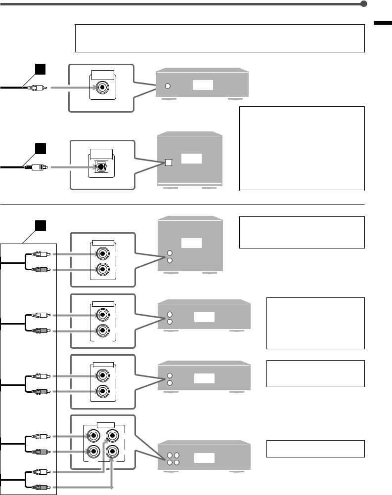
Illustrations of the input/output terminals below are typical examples.
When you connect other components, refer also to their manuals since the terminal names actually printed on the rear vary among the components.
A |
COAXIAL |
|
|
|
DIGITAL OUT |
|
|
|
|
|
DVD |
B |
OPTICAL |
|
TV |
|
DIGITAL OUT |
||
|
|
|
|
C |
|
|
|
|
AUDIO OUT |
TV |
|
|
|
||
|
|
LEFT |
|
|
|
RIGHT |
|
|
AUDIO OUT |
|
|
|
|
LEFT |
DVD |
|
|
|
|
|
|
RIGHT |
|
|
FRONT/MIX |
|
|
|
LINE OUT |
|
|
|
|
LEFT |
CD |
|
|
|
|
|
|
RIGHT |
|
|
AUDIO |
|
|
|
|
|
LEFT |
|
|
|
RIGHT |
|
OUT |
IN |
VCR |
|
|
||
•When shipped from the factory, the DIGITAL IN terminals have been set for use with the following components.
–DIGITAL 1 (coaxial): For DVD player
–DIGITAL 2 (optical): For digital TV tuner
If you connect other components, change the digital input (DIGITAL IN) terminal setting correctly. See “Setting the Digital Input Terminals” on page 10.
•Select the digital input mode correctly. See “Selecting the Analog or Digital Input Mode” on page 11.
•Connect the video input directly to the video output on the DVD player and/or VCR.
•You can also connect the digital TV tuner using the optical digital cable (see above).
•Connect the video out directly to the video input on the TV.
•To enjoy the software encoded with
Dolby Digital or DTS Digital
Surround, connect the DVD player using one of the DIGITAL IN terminals (see above).
You can also connect the CD player using one of the DIGITAL IN terminals (see above).
Connect the video out directly to the video input on the TV.
Started Getting
7

Basic Operations
This manual mainly explains operations using the buttons and controls on the front panel. You can also use the buttons on the remote control if they have the similar names (or marks) as those on the front panel.
If operations using the remote control are different from those using the front panel, they are then explained.
• You can also see “Mastering Remote Operations” on page 32.
STANDBY lamp |
|
|
|
|
|
|
|
|
|
Display |
|
|
|
|
|
|
||
STANDBY |
|
|
|
|
|
|
|
|
|
|
|
|
|
|
|
|
|
|
POWER |
|
TV DILECT |
|
|
|
|
|
|
RX-E100 |
HOME THEATER RECEIVER |
|
|
|
|
||||
|
|
|
|
CONTROL |
ANALOG |
L |
C |
R |
PRO LOGIC |
SLEEP |
|
TUNED |
ST |
AUTO |
MUTING |
|
|
|
|
|
|
|
LPCM |
SUBWFR LFE DSP |
|
|
|
|
|
MH |
|
|
|
||||
|
|
|
|
|
|
|
|
|
|
|
|
|
||||||
|
|
|
|
|
DOLBY D |
LS |
S |
RS |
DGTL AUTO |
|
|
|
|
|
KH |
INPUT |
SURROUND |
DSP |
|
|
SETTING |
ADJUST |
|
DTS |
INPUT ATT |
|
|
|
|
|
VOL |
||||||
|
|
|
MEMORY |
|
|
|
|
|
|
|
|
|
|
ANALOG/DIGITAL |
ON/OFF |
MODE |
||
|
|
|
|
|
|
|
|
|
|
|
|
|
|
|
|
|
|
MASTER VOLUME |
|
|
|
|
|
|
|
|
|
|
|
|
|
|
|
|
INPUT ATT |
|
|
|
D I G I T A L |
|
|
|
DVD |
|
|
TV |
|
VCR |
CD |
FM |
|
|
AM |
|
|
|
|
|
|
|
|
|
|
|
|
|
|
|
|||||||
|
S U R R O U N D |
D I G I T A L |
|
|
|
|
|
|
|
|
|
|
|
|
|
|
|
|
1 |
|
|
|
|
|
|
|
|
|
|
2 |
|
|
|
|
|
|
3 |
1 Turn On the Power
Press POWER (or AUDIO of the POWER buttons on the remote control).
STANDBY
The STANDBY lamp goes off. The name of the
current source (or station frequency) appears on POWER the display.
Current volume level is shown here
L R
LPCM
DGTL AUTO
VOL


Current source name appears
To turn off the power (into standby)
Press POWER (or AUDIO) again. |
STANDBY |
|
The STANDBY lamp lights up. |
POWER |
|
A small amount of power is consumed in standby |
||
|
||
mode. To turn the power off completely, unplug |
|
|
the AC power cord. |
|
2 Select the Source to Play
Press one of the source selecting buttons.
DVD |
TV |
VCR |
CD |
FM |
AM |
DVD : Select the DVD player.
TV : Select the TV sound.
VCR : Select the VCR.
CD : Select the CD player.
FM : Select an FM broadcast.
AM : Select an AM broadcast.
Note:
When you have connected some digital source components using the digital terminals (see page 6), see “Basic Settings” on pages 10 and
11 to finish the digital input terminal setting and digital input mode setting correctly before use.
3 Adjust the Volume
To increase the volume, press and hold
MASTER VOLUME (or VOLUME + on the
remote control).
MASTER VOLUME
To decrease the volume, press and hold MASTER VOLUME (or VOLUME – on the remote control).
CAUTION:
Always set the volume to the minimum before starting any source. If the volume is set at its high level, the sudden blast of sound energy can permanently damage your hearing and/or ruin your speakers.
Notes:
•The volume level can be adjusted within the range of “0” (minimum) to “70” (maximum).
•Each time you press the button, the volume level changes by 2 steps from “0” (minimum) to “14” and by 1 step from “14” to “70” (maximum).
8
To turn off the sounds temporarily

 Remote
Press MUTING on the remote control to mute 
 ONLY the sound through all speakers connected.
MUTING
TO
“MUTING” appears on the display and the volume turns off (the volume level indicator goes off).
To restore the sound, press MUTING again so that “MUTING OFF” appears on the display.
• Pressing MASTER VOLUME  /
/ (or VOLUME +/–) also restores the sound.
Turning Off the Power |
Remote |
with the Timer |
ONLY |
You can fall asleep while listening to music — Sleep Timer.
Press SLEEP on the remote control repeatedly.
The SLEEP indicator lights up on the display, and the shut-off time changes in 10 minute intervals.
SLEEP
L |
R |
SLEEP |
LPCM
DGTL AUTO
VOL 


 10
10  20
20  30
30  40
40  50
50  60
60  70
70  80
80  90
90
0 (Canceled) 
When the shut-off time comes
The receiver turns off automatically.
To check or change the time remaining until the shut-off time
Press SLEEP once.
The remaining time (in minutes) until the shut-off time appears.
• To change the shut-off time, press SLEEP repeatedly.
To cancel the Sleep Timer
Press SLEEP repeatedly until “SLEEP 0” appears on the display. (The SLEEP indicator goes off.)
• Turning off the power also cancels the Sleep Timer.
Basic adjustment auto memory
This receiver memorizes sound settings for each source ....
•when you turn on the power,
•when you change the source, and
•when you change the analog/digital input mode (see page 11).
When you change the source, the memorized settings for the newly selected source are automatically recalled.
The following can be stored for each source:
•Analog/digital input mode (see page 11)
•Input attenuator mode (see page 17)
•Balance (see page 17)
•Bass boost (see page 18)
•Tone adjustment (see page 19)
•Subwoofer output level (see page 19)
•Surround mode settings (see pages 25, 29) Theater Surround settings (see pages 27, 30) DAP mode settings (see pages 28, 31)
Note:
If the source is FM or AM, you can assign a different setting for each band.
For recording
You can record sounds of any source playing through the receiver to the VCR connected to the VCR jacks.
While recording, you can listen to the selected sound source at whatever sound level you like without affecting the sound levels of the recording.
Note:
Sound adjustments (see page 17) and DSP modes (see page 22) cannot affect the recording.
Signal and speaker indicators on the display
L |
C |
R |
ANALOG |
L |
|
C |
|
R |
PRO LOGIC |
SLEEP |
L C |
R |
||||||
|
|
|
LPCM |
|
|
|
|
|
|
DSP |
|
|
|
|
|
|
|
|
|
|
LFE |
SUBWFR LFE |
SUBWFR |
|
|
||||||||||||
|
|
DOLBY D |
LS |
|
S |
|
RS |
DGTL AUTO |
|
|
||||||||
|
|
|
|
|
|
|
|
|
|
|
|
|
|
|
|
|
||
|
|
|
DTS |
|
|
|
|
|
|
INPUT ATT |
|
|
|
|
|
|
|
|
|
|
|
|
|
|
|
|
|
|
|
|
|
|
|
|
|
|
|
LS |
S |
RS |
|
|
|
|
|
|
|
|
|
|
|
|
|
|
|
|
|
|
|
|
|
|
|
|
|
LS |
|
RS |
|
||||||
Signal indicators |
|
|
|
|
|
|
|
|
Speaker indicators |
|||||||||
The following signal indicators light up —:
L: • When digital input is selected: Lights up when the left channel signal comes in.
•When analog input is selected: Always lights up.
R:• When digital input is selected: Lights up when the right channel signal comes in.
•When analog input is selected: Always lights up.
C:Lights up when the center channel signal comes in. LS: Lights up when the left rear channel signal comes in. RS: Lights up when the right rear channel signal comes in.
S: Lights up when the monaural rear channel signal comes in. LFE: Lights up when the LFE channel signal comes in.
The speaker indicators light up as follows:
•The subwoofer speaker indicator (SUBWFR) lights up when “SUBWFR” is set to “YES” (see page 12).
•The other speaker indicators light up only when the corresponding speaker is activated AND when the corresponding speaker is required for the DSP mode currently selected.
Operations Basic
9
Basic Settings
|
CONTROL |
|
|
5/°/3/2 |
Display |
STANDBY |
|
|
POWER |
TV DILECT |
RX-E100 HOME THEATER RECEIVER |
|
|
|
CONTROL |
|
ANALOG |
L |
C |
R |
PRO LOGIC |
SLEEP |
TUNED |
ST |
AUTO |
MUTING |
|
|
|
|
|
|
|
LPCM |
SUBWFR LFE DSP |
|
|
|
|
MH |
|
|
|
||||
|
|
|
|
|
DOLBY D |
LS |
S |
RS |
DGTL AUTO |
|
|
|
|
KH |
INPUT |
SURROUND |
DSP |
|
SETTING |
ADJUST |
|
MEMORY |
DTS |
INPUT ATT |
|
|
|
|
VOL |
||||||
|
|
|
|
|
|
|
|
|
|
|
|
ANALOG/DIGITAL |
ON/OFF |
MODE |
|||
|
|
|
|
|
|
|
|
|
|
|
|
|
|
|
|
|
MASTER VOLUME |
|
|
|
|
|
|
|
|
|
|
|
|
|
|
|
INPUT ATT |
|
|
D I G I T A L |
|
|
|
|
DVD |
|
|
TV |
VCR |
CD |
FM |
|
|
AM |
|
|
|
|
|
|
|
|
|
|
|
|
|
|
|||||||
S U R R O U N D |
D I G I T A L |
|
|
|
|
|
|
|
|
|
|
|
|
|
|
|
|
SETTING |
Source selecting buttons |
INPUT |
|
(DVD, TV, CD) |
ANALOG/DIGITAL |
Setting the Digital Input |
Remote |
Terminals |
NOT |
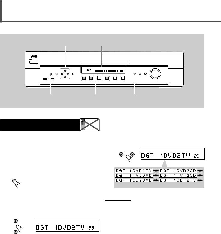
When you use the digital input terminals, register what components are connected to which terminals (DIGITAL IN 1/2) so that the correct source name will appear when you select the digital source.
Before you start, remember...
There is a time limit in doing the following steps. If the setting is canceled before you finish, start from step 1 again.
3Press CONTROL 3(or 2) to select the appropriate digital terminal setting.
•Each time you press the button, the display changes to show the following:
|
CONTROL |
|
|
||
ANALOG |
L |
C |
R |
PRO LOGIC |
|
LPCM |
SUBWFR LFE |
DSP |
|
||
DOLBY D |
|
|
DGTL AUTO |
|
|
DTS |
LS |
S |
RS |
INPUT ATT |
VOL |
1 Press SETTING.
SETTING |
The CONTROL buttons now work for basic |
|
settings. |
2Press CONTROL °(or 5) repeatedly until “DGT (Digital)” (with the current setting) * appears on the display.
CONTROL
(back to the begining)
Note:
When shipped from the factory, the DIGITAL IN terminals have been set for use with the following components.
•DIGITAL 1 (coaxial): For DVD player
•DIGITAL 2 (optical): For digital TV tuner
VOL |
*“1DVD2TV” is the initial setting. If you have already changed the setting, another combination will be shown.
10
Selecting the Analog or Digital Input Mode
When you have connected digital source components using both the analog connection and the digital connection methods (see page 6), you need to select the input mode correctly.
1Press one of the source selecting buttons (DVD, TV, or CD)* for which you want to change the input mode.
If the following symptoms occur while playing Dolby Digital or DTS Digital Surround software with “DGTL AUTO” selected, follow the procedure below.
•Sound does not come out at the beginning of playback.
•Noise comes out while searching or skipping chapters or tracks.
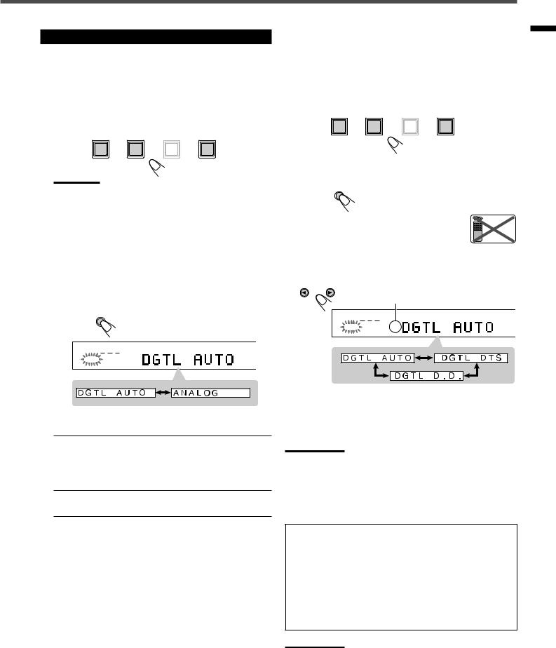
1Press one of the source selecting buttons (DVD, TV, or CD) for which you want to change the input mode.
DVD |
TV |
VCR |
CD |
Settings Basic
DVD |
TV |
VCR |
CD |
Note:
*Among the sources listed above, you can select the digital input only for the sources which you have selected the digital input terminals for. (See “Setting the Digital Input Terminals” on page 10.)
2Press INPUT ANALOG/DIGITAL (or INPUT A/ D on the remote control) to select the analog or digital input mode.
•Each time you press the button, the input mode alternates between the analog input (ANALOG) and the digital input (DGTL AUTO).
INPUT
ANALOG/DIGITAL
INPUT |
ATT |
|
|
L |
C |
R |
MUTIN |
SUBWFR LFE |
MHZ |
||
DOLBY D |
|
DGTL AUTO |
KHZ |
LS |
RS |
VOL |
|
2 Press INPUT ANALOG/DIGITAL (or INPUT A/D) to select the digital input mode (DGTL AUTO).
INPUT
ANALOG/DIGITAL
INPUT ATT
3 Press CONTROL 3(or 2) to select “DGTL D.D.” or “DGTL DTS” while “DGTL AUTO” still remains on the display.
• Each time you press the button, the digital input mode changes as follows:
CONTROL
When “DGTL D.D.” or “DGTL DTS” is selected, “AUTO” goes off.
L C |
R |
MU |
SUBWFR LFE |
MH |
|
DOLBY D |
DGTL AUTO |
KH |
LS |
RS |
VO |
DGTL AUTO : Select this for the digital input mode. The receiver automatically detects the incoming signal format. (The DGTL AUTO indicator lights up on the display, then the digital signal indicator for the detected signals lights up.)
ANALOG : Select this for the analog input mode. (Initial setting when shipped from the factory)
•To play back software encoded with Dolby Digital, select “DGTL D.D.”
•To play back software encoded with DTS Digital Surround, select “DGTL DTS.”
Note:
When you turn off the power or select another source, “DGTL DTS” and “DGTL D.D.” are canceled and the digital input mode is automatically reset to “DGTL AUTO.”
The following are the analog/digital signal indicators on the display to indicate what type of the signal comes into the receiver.
ANALOG : Lights when the analog input is selected.
LPCM : Lights when Linear PCM signals come in.
DOLBY D : • Lights when Dolby Digital signals come in.
• Flashes when “DGTL D.D.” is selected for software not encoded with Dolby Digital.
DTS : • Lights when DTS Digital Surround signals come in.
• Flashes when “DGTL DTS” is selected for software not encoded with DTS Digital Surround.
Note:
When “DGTL AUTO” cannot recognize the incoming signals, no digital signal indicators light up on the display.
11
Loading...