


 Loading...
AUDIO / VIDEO CONTROL RECEIVER
RX-D211S / RX-D212B
INSTRUCTIONS
For Customer Use:
Enter below the Model No. and Serial No. which are located either on the rear, bottom or side of the cabinet. Retain this information for future reference.
Model No.
Serial No.
LVT1557-001A
[J]
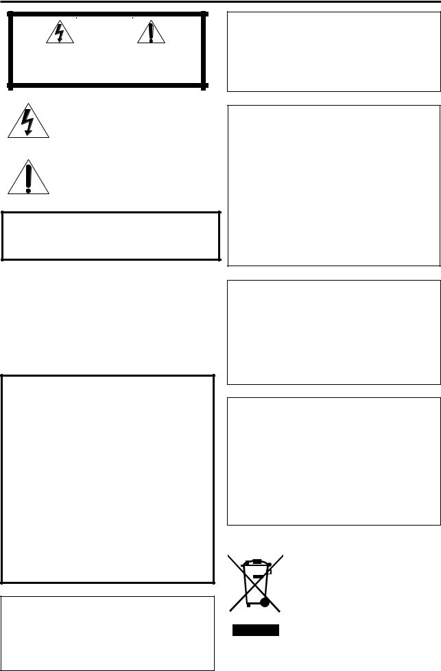
Warnings, Cautions, and Others
Mises en garde, précautions et indications diverses
|
|
CAUTION |
|
|
|
RISK OF ELECTRIC SHOCK |
|
|
|
DO NOT OPEN |
|
|
|
|
|
|
|
|
|
CAUTION: |
TO REDUCE THE RISK OF ELECTRIC SHOCK, |
||
|
DO NOT REMOVE COVER (OR BACK). |
||
|
NO USER SERVICEABLE PARTS INSIDE. |
||
REFER SERVICING TO QUALIFIED SERVICE PERSONNEL.
The lightning flash with arrowhead symbol, within an equilateral triangle is intended to alert the user to the presence of uninsulated "dangerous voltage" within the product's enclosure that may be of sufficient magnitude to constitute a risk of electric shock to persons.
The exclamation point within an equilateral triangle is intended to alert the user to the presence of important operating and maintenance (servicing) instructions in the literature accompanying the appliance.
WARNING: TO REDUCE THE RISK OF FIRE OR ELECTRIC SHOCK, DO NOT EXPOSE THIS APPLIANCE TO RAIN OR MOISTURE.
CAUTION
To reduce the risk of electrical shocks, fire, etc.:
1.Do not remove screws, covers or cabinet.
2.Do not expose this appliance to rain or moisture.
ATTENTION
Afin d’éviter tout risque d’électrocution, d’incendie, etc.:
1.Ne pas enlever les vis ni les panneaux et ne pas ouvrir le coffret de l’appareil.
2.Ne pas exposer l’appareil à la pluie ni à l’humidité.
Caution––  STANDBY/ON button!
Disconnect the mains plug to shut the power off completely (the standby lamp goes off). When installing the apparatus, ensure
that the plug is easily accessible. The  STANDBY/ON button in any position does not disconnect the mains line.
•When the unit is on standby, the standby lamp lights red.
•When the unit is turned on, the standby lamp goes off. The power can be remote controlled.
Attention—Touche  STANDBY/ON!
Déconnectez la fiche secteur pour mettre l’appareil complètement hors tension (le témoin d’attente s’éteint). Lors de l’installation de l’appareil, assurez-vous que la fiche soit
facilement accessible. La touche  STANDBY/ON dans n’importe quelle position ne déconnecte pas l’appareil du secteur.
•Quand l’appareil est en mode d’attente, le témoin d’attente s’allume en rouge.
•Quand l’appareil est sous tension, le témoin d’attente s’éteint.
L’alimentation ne peut pas être commandée à distance.
CAUTION
Changes or modifications not approved by JVC could void the user’s authority to operate the equipment.
ATTENTION
Des changements ou modifications non approuvés par JVC pourront invalider l’autorité de l’utilisateur à opérer cet appareil.
For U.S.A
This equipment has been tested and found to comply with the limits for a Class B digital device, pursuant to part 15 of the FCC Rules. These limits are designed to provide reasonable protection against harmful interference in a residential installation.
This equipment generates, uses and can radiate radio frequency energy and, if not installed and used in accordance with the instructions, may cause harmful interference to radio communications. However, there is no guarantee that interference will not occur in a particular installation. If this equipment does cause harmful interference to radio or television reception, which can be determined by turning the equipment off and on, the user is encouraged to try to correct the interference by one or more of the following measures:
Reorient or relocate the receiving antenna.
Increase the separation between the equipment and receiver. Connect the equipment into an outlet on a circuit different from that to which the receiver is connected.
Consult the dealer or an experienced radio/TV technician for help.
Declaration of Conformity:
Trade Name: JVC
Model Number: RX-D211S/RX-D212B
Responsible Party: JVC Americas Corp.
Address: 1700 Valley Road, Wayne New Jersey 07470
Telephone Number: 973-317-5000
This device complies with Part 15 of the FCC Rules. Operation is subject to the following two conditions:
(1)This device may not cause harmful interference.
(2)This device must accept any interference received, including interference that may cause undesired operation.
For Canada/pour Le Canada
THIS DIGITAL APPARATUS DOES NOT EXCEED THE CLASS B LIMITS FOR RADIO NOISE EMISSIONS FROM
DIGITAL APPARATUS AS SET OUT IN THE INTERFERENCE-CAUSING EQUIPMENT STANDARD
ENTITLED “DIGITAL APPARATUS,” ICES-003 OF THE DEPARTMENT OF COMMUNICATIONS.
CET APPAREIL NUMERIQUE RESPECTE LES LIMITES DE
BRUITS RADIOELECTRIQUES APPLICABLES AUX APPAREILS NUMERIQUES DE CLASSE B PRESCRITES
DANS LA NORME SUR LE MATERIEL BROUILLEUR; “APPAREILS NUMERIQUES”, NMB-003 EDICTEE PAR LE MINISTRE DES COMMUNICATIONS.
Note to CATV system installer:
This reminder is provided to call the CATV system installer’s attention to Section 820-40 of the NEC which provides guidelines for proper grounding and, in particular, specifies that the cable ground shall be connected to the grounding system of the building, as close to the point of cable entry as practical.
[European Union Only]
[Union européenne seulement]
G-1

Table of Contents
Parts identification ................................................ |
2 |
Getting started ...................................................... |
4 |
Before Installation .................................................................. |
4 |
Checking the supplied accessories ....................................... |
4 |
Putting batteries in the remote control ................................... |
4 |
Connecting antennas ............................................................. |
5 |
Connecting the speakers ....................................................... |
6 |
Connecting audio/video components .................................... |
7 |
Connecting the power cord .................................................. |
10 |
USB connection ................................................................... |
11 |
Basic operations ................................................. |
12 |
1 Turn on the power ............................................................. |
12 |
2 Select the source to play .................................................. |
12 |
3 Adjust the volume ............................................................. |
13 |
Turning off the sounds temporarily ...................................... |
14 |
Changing the display brightness .......................................... |
14 |
Turning off the power with the Sleep Timer ......................... |
14 |
FM/AM tuner operations ..................................... |
15 |
Tuning in to FM/AM stations manually ................................. |
15 |
Using preset tuning .............................................................. |
15 |
Selecting the FM reception mode ........................................ |
16 |
XM Satellite Radio operations ............................ |
17 |
Preparation .......................................................................... |
17 |
Listening to XM Satellite Radio ............................................ |
18 |
Using preset tuning .............................................................. |
19 |
Changing the channel information ....................................... |
19 |
Basic settings ...................................................... |
20 |
Setting the speaker information easily |
|
—Quick Speaker Setup ................................................. |
20 |
Basic setting items ............................................................... |
21 |
Operating procedure ............................................................ |
22 |
Setting the speakers ............................................................ |
22 |
Activating the EX/ES/PLIIx setting—EX/ES/PLIIx ............... |
23 |
Selecting the main or sub channel—DUAL MONO ............. |
24 |
Setting bass sound .............................................................. |
24 |
Using the Midnight mode—MIDNIGHT MODE .................... |
24 |
Setting the digital input (DIGITAL IN) terminals |
|
—DIGITAL IN 1/2/3 ........................................................ |
25 |
Selecting the component video input mode |
|
—DVD VIDEO IN/VCR VIDEO IN/DBS VIDEO IN ......... |
25 |
Sound adjustments ............................................. |
26 |
Basic adjustment items ........................................................ |
26 |
Operating procedure ............................................................ |
26 |
Adjusting the speaker output levels ..................................... |
27 |
Adjusting the equalization patterns |
|
—D EQ 63Hz/250Hz/1kHz/4kHz/16kHz ........................ |
27 |
Adjusting the bass sounds ................................................... |
28 |
Adjusting the sound parameters for the |
|
Surround/DSP modes ................................................... |
28 |
Creating realistic sound fields ........................... |
30 |
Reproducing theater ambience ........................................... |
30 |
Introducing the Surround modes ......................................... |
30 |
Introducing the DSP modes ................................................. |
32 |
Using the Surround/DSP modes ......................................... |
33 |
Activating the Surround/DSP modes ................................... |
34 |
AV COMPU LINK remote control system .......... |
35 |
Operating other JVC products ........................... |
37 |
Operating other manufacturers’ products ........ |
39 |
Troubleshooting .................................................. |
42 |
Specifications ...................................................... |
43 |
1
Parts identification
|
A/V CONTROL RECEIVER |
|
|||
|
REMOTE CONTROL RM-SRXD211J |
|
|||
|
MUTING |
|
|
AUDIO |
|
1 |
|
|
|
|
|
|
|
VCR |
DBS/ |
TV/SIRIUS |
|
2 |
DVR/DVD |
CATV |
|
||
|
|
|
|
|
|
|
DVR/DVD |
VCR |
DBS |
TV |
|
3 |
USB |
XM |
FM/AM |
SIRIUS |
|
|
|
||||
4 |
TV VOL |
CHANNEL |
VOLUME |
u |
|
|
|
|
DVR |
|
|
|
|
|
|
|
i |
5 |
|
|
|
DVD |
|
|
SELECT |
|
|
||
|
|
|
|
||
6 |
TUNING |
CAT |
|
TUNING |
|
|
|
|
|||
|
TOP MENU |
|
|
MENU |
|
7 |
|
|
|
|
|
|
|
SET |
|
|
|
|
SURROUND |
|
|
DISPLAY |
|
8 |
|
|
|
|
o |
|
TV/VIDEO |
|
|
|
|
9 |
|
1 |
2 |
3 |
|
|
ANALOG/DIGITAL |
|
|
|
|
p |
|
4 |
5 |
6 |
; |
q |
FM MODE |
|
|
|
|
|
7 |
8 |
9 |
|
|
|
MEMORY |
RETURN |
|
10/100 |
|
w |
|
10 |
0 |
10 |
a |
|
D.EQ FREQ |
DIRECT |
BAND |
PREV |
|
e |
|
C.TONE |
EFFECT |
DIMMER |
s |
|
d |
||||
|
|
|
|
||
|
|
|
|
|
|
|
D.EQ LEVEL |
B.BOOST |
TEST |
SLEEP |
f |
r |
|
g |
|
|
|
t |
CENTER SUBWFR |
h |
L — FRONT — R |
j |
|
|
|
|
y |
|
|
L — SURR — R |
L — S. BACK — R |
|
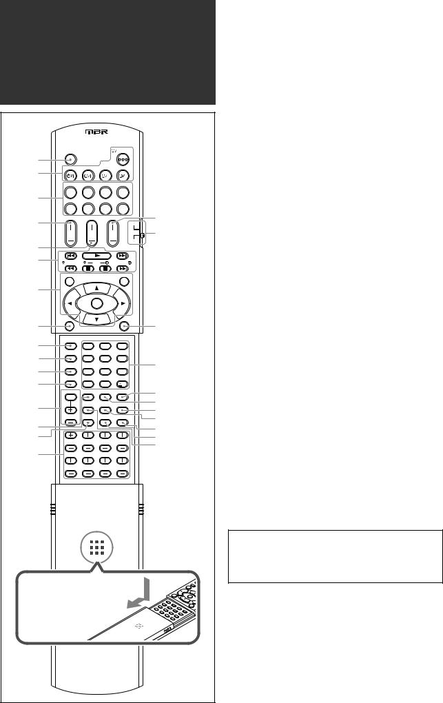
To open the cover of the remote control, push here then slide downward
Remote control
See pages in parentheses for details.
1 MUTING button (14)
2 Standby/on buttons (12, 37 – 41)
 AUDIO, DVR/DVD
  , VCR
, VCR  , DBS/CATV
  ,
,
TV/SIRIUS 
3 Source selecting buttons (12, 16, 17, 34, 37 – 41) DVR/DVD, VCR, DBS, TV, USB, XM, FM/AM, SIRIUS
4 TV VOL (volume) +/– button (37, 39)
5 CHANNEL +/– button (37 – 41)
6• Operating buttons for video components (37, 38, 40, 41)
4, 3, ¢, 1, 7, 8, ¡
•Operating buttons for FM/AM tuner (15) ( TUNING, TUNING 9
•Operating buttons for XM Satellite Radio or SIRIUS
Satellite Radio (18, 37)
SELECT*, ( CAT, CAT 9
7Operating buttons for DVD recorder or DVD player** (38, 41)
TOP MENU, MENU, cursor buttons (3, 2, 5, ∞), SET
8 SURROUND button (34)
9 TV/VIDEO button (37, 39)
p ANALOG/DIGITAL button (13) q FM MODE button (16)
w MEMORY button (15, 19)
e Adjusting buttons for Digital Equalizer (27) D.EQ FREQ, D.EQ LEVEL +/–
r DIRECT button (18)
t B (bass). BOOST button (28)
yAdjusting buttons for speaker and subwoofer output levels
(27)
FRONT L +/–, FRONT R +/–, CENTER +/–, SUBWFR +/–,
SURR L +/–, SURR R +/–, S.BACK L +/–, S.BACK R +/– u VOLUME +/– button (13)
i DVR/DVD mode selector (38, 41) o DISPLAY button (19, 37)
;• Numeric buttons (16, 18, 19, 37 – 41)
1 – 10, 0, h10, +10/100+
• RETURN button (37) a PREV* button (37)
s BAND* button (37) d DIMMER button (14) f EFFECT button (28) g SLEEP button (14) h TEST button (27)
j C (center).TONE button (29)
* For SIRIUS Satellite Radio only
**These buttons can be used for operating a DVD recorder (JVC product ONLY) or DVD player with the mode selector set to
“DVR” or “DVD” (see page 38).
If these buttons do not function normally, use the remote control supplied with your DVD recorder or DVD player. Refer also to the manuals supplied with the DVD recorder or DVD player for details.
•When operating a DVD recorder (for JVC products ONLY), set the mode selector (i) to “DVR.”
•When operating a DVD player, set the mode selector (i) to “DVD.”
2
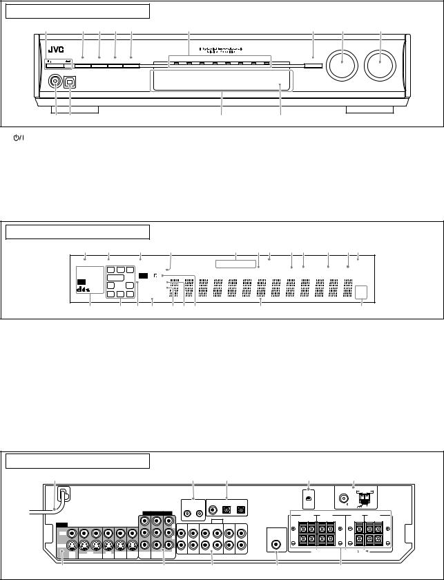
See pages in parentheses for details.
Front panel |
|
|
|
|
|
|
|
|
|
|
|
||
1 |
2 |
3 |
4 |
5 |
6 |
|
|
|
|
|
7 |
8 |
9 |
|
|
|
|
|
|
|
|
|
|
|
|
SOURCE |
MASTER |
|
A U D I O / V I D E O C O N T R O L R E C E I V E R |
|
|
|
|
|
|
|
|
SELECTOR |
VOLUME |
||
|
|
|
|
|
|
|
|
|
/ MULTI JOG |
|
|||
|
|
|
|
DVR / DVD |
VCR |
DBS |
TV/SIRIUS |
USB |
XM |
FM |
AM |
|
|
STANDBY/ON |
DIMMER |
SETTING |
ADJUST |
SURROUND |
|
|
|
|
|
|
SET / TUNER PRESET |
|
|
PHONES |
USB |
|
|
|
|
|
|
|
|
|
|
|
|
p q |
|
|
|
|
|
w |
|
|
|
e |
|
|
|
1 |
STANDBY/ON button and standby lamp (12) |
8 |
• SOURCE SELECTOR (12, 16, 17) |
2 |
DIMMER button (14) |
|
• MULTI JOG (16, 19, 20, 22, 26, 34) |
3 |
SETTING button (20, 22) |
9 |
MASTER VOLUME control (13) |
4 |
ADJUST button (26) |
p PHONES jack (13) |
|
5 |
SURROUND button (34) |
q USB terminal (11) |
|
6 |
Source lamps |
w Display window (see below) |
|
|
DVR/DVD, VCR, DBS, TV/SIRIUS, USB, XM, FM, AM |
e Remote sensor (4) |
|
7• SET button (20, 22, 26)
• TUNER PRESET button (16, 19)
Display window
1 2 |
3 4 |
5 6 7 8 9 0 - = |
ANALOG |
DUAL MONO |
|
AUTO SURR |
TUNED |
STEREO |
AUTO MUTING |
|
|
SLEEP |
||||
DIGITAL AUTO |
L |
C |
R |
|
HEADPHONE |
|
DIGITAL EQ |
C.TONE |
B.BOOST |
MIDNIGHT |
INPUT ATT |
||
LINEAR PCM |
S.WFR |
LFE |
PL |
x |
|
|
|
|
|
|
|
||
DIGITAL |
NEO : 6 |
DSP |
|
|
|
|
|
|
|
||||
LS |
S |
RS |
|
|
|
|
|
|
|
|
|||
96 / 24 |
|
3D-PHONIC |
|
|
|
|
|
|
MHz |
||||
SB |
SB |
SB |
|
|
|
|
|
|
|
||||
|
|
VIRTUAL SB |
|
|
|
|
|
|
kHz |
||||
~ |
|
! |
|
@ # |
$ % ^ |
|
|
& |
|
|
|
* |
|
1 ANALOG indicator (13)
2 DUAL MONO indicator (24)
3 AUTO SURR (surround) indicator (34)
4 HEADPHONE indicator (13, 31)
5 FM/AM tuner operation indicators (15) TUNED, STEREO
6 DIGITAL EQ indicator (27)
7 AUTO MUTING indicator (16)
8 C.TONE indicator (29)
9 B (bass).BOOST indicator (28)
0 MIDNIGHT indicator (24)
- INPUT ATT (attenuate) indicator (28)
= SLEEP indicator (14)
~ Digital signal format indicators (13, 30, 31)
DIGITAL AUTO, LINEAR PCM, 


 ,
,  , 96/24
! Signal and speaker indicators (14) @ NEO:6 indicator (31)
# VIRTUAL SB indicator (33)
$ 3D-PHONIC indicator (31, 32)
% DSP indicator (31, 32)
^ 

 and
and 

 indicator (30 – 32) & Main display
*Frequency unit indicators
MHz (for FM stations), kHz (for AM stations)
Rear panel
1 |
|
|
|
|
|
|
|
|
2 |
|
3 |
|
|
|
|
|
|
|
|
|
|
AV |
DIGITAL IN |
|
|
|
|
|
|
|
|
|
|
|
1(DVR/DVD) |
2(DBS) |
3(VCR) |
|
|
|
|
|
|
|
|
|
COMPU LINK-III |
|
|
||
|
|
|
|
|
COMPONENT VIDEO |
|
|
|
|
|
||
|
|
|
|
|
|
|
|
|
|
AUDIO |
|
|
VIDEO |
|
|
|
|
|
|
Y |
TV/SIRIUS |
DBS |
VCR |
DVR |
DVR/DVD |
|
|
|
|
|
|
L IN |
IN |
OUT(REC) IN(PLAY) |
OUT(REC) |
IN(PLAY) |
||
VIDEO |
|
|
|
|
|
|
|
|
|
|
|
|
|
|
|
|
|
|
|
PB |
|
|
|
|
|
S-VIDEO |
|
|
|
|
|
|
|
|
|
|
|
|
DBS |
VCR |
DVR |
DVR/DVD |
MONITOR |
|
|
PR |
R |
|
|
|
|
VCR(DBS) |
DVR/DVD |
MONITOR |
|
|
|
|
|
|||||
IN |
OUT(REC) IN(PLAY) |
OUT(REC) |
IN(PLAY) |
OUT |
IN |
IN |
OUT |
|
|
|
|
|
45
ANTENNA |
AM LOOP |
XM
|
|
|
|
FM 75 |
|
|
|
|
|
|
|
COAXIAL |
|
AM EXT |
|
SURROUND BACK |
SURROUND |
CENTER |
|
FRONT |
|||
SPEAKERS |
SPEAKERS |
SPEAKER |
SPEAKERS |
||||
RIGHT |
LEFT |
RIGHT |
LEFT |
|
|
RIGHT |
LEFT |
SUBWOOFER |
|
|
|
|
|
|
|
OUT |
|
|
|
|
|
|
|
|
CAUTION:SPEAKER IMPEDANCE 6 |
-16 |
|
|
|||
6 |
7 |
8 |
9 |
p |
1 Power cord (10)
2 AV COMPU LINK-III terminals (35)
3DIGITAL IN terminals (10)
•Coaxial: 1(DVR/DVD)
•Optical: 2(DBS)
•Optical: 3(VCR)
4 XM jack (5)
5 FM/AM ANTENNA terminals (5)
6VIDEO jacks (7– 9)
VIDEO (composite video) jacks, S-VIDEO jacks
•Input: DBS IN, VCR IN (PLAY), DVR/DVD IN (PLAY)
•Output: VCR OUT (REC), DVR OUT (REC), MONITOR OUT
7COMPONENT VIDEO (Y, PB, PR) jacks (7– 9) VCR (DBS) IN, DVR/DVD IN, MONITOR OUT
8AUDIO jacks (7 – 9)
•Input: TV/SIRIUS IN, DBS IN, VCR IN (PLAY), DVR/DVD IN (PLAY)
•Output: VCR OUT (REC), DVR OUT (REC)
9 SUBWOOFER OUT jack (6)
pSpeakers terminals (6)
SURROUND BACK SPEAKERS, SURROUND SPEAKERS, CENTER SPEAKER, FRONT SPEAKERS
3
Getting started
Before Installation
General precautions
•Be sure your hands are dry.
•Turn the power off to all components.
•Read the manuals supplied with the components you are going to connect.
Locations
•Install the receiver in a location that is level and protected from moisture and dust.
•The temperature around the receiver must be between –5˚C and 35˚C (23˚F and 95˚F).
•Make sure there is good ventilation around the receiver. Poor ventilation could cause overheating and damage the receiver.
•Leave sufficient distance between the receiver and the TV.
Handling the receiver
•Do not insert any metal object into the receiver.
•Do not disassemble the receiver or remove screws, covers, or cabinet.
•Do not expose the receiver to rain or moisture.
•Do not pull on the power cord to unplug the cord. When unplugging the cord, always grasp the plug so as not to damage the cord.
•When you are away on travel or otherwise for an extended period or time, remove the plug from the wall outlet. A small amount of power is always consumed while the power cord is connected to the wall outlet.
The receiver has a built-in cooling fan which operates while the receiver is turned on. Be sure to leave enough ventilation to obtain sufficient cooling effect.
CAUTION:
Do not connect the AC power plug to the wall outlet until all connections are completed.
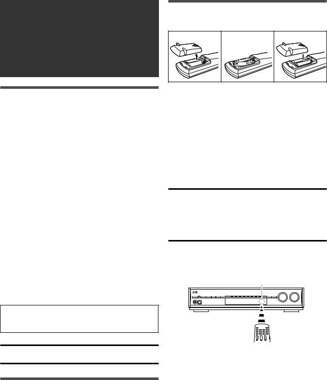
Putting batteries in the remote control
Before using the remote control, put two supplied batteries first.
1 |
2 |
3 |
1Press and slide the battery cover on the back of the remote control.
2Insert batteries.
Make sure to match the polarity: (+) to (+) and (–) to (–).
3 Replace the cover.
If the range or effectiveness of the remote control decreases, replace the batteries. Use two R6(SUM-3)/AA(15F) type dry-cell batteries.
•Supplied batteries are for initial setup. Replace for continued use.
CAUTION:
Follow these precautions to avoid leaking or cracking cells:
•Place batteries in the remote control so they match the polarity:
(+) to (+) and (–) to (–).
•Use the correct type of batteries. Batteries that look similar may differ in voltage.
•Always replace both batteries at the same time.
•Do not expose batteries to heat or flame.
When using the remote control, aim the remote control directly at the remote sensor on the front panel.
Remote sensor
Checking the supplied accessories
Check to be sure you have all of the following supplied accessories. If anything is missing, contact your dealer immediately.
•Remote control (× 1)
•Batteries (× 2)
•AM loop antenna (× 1)
•FM antenna (× 1)
4
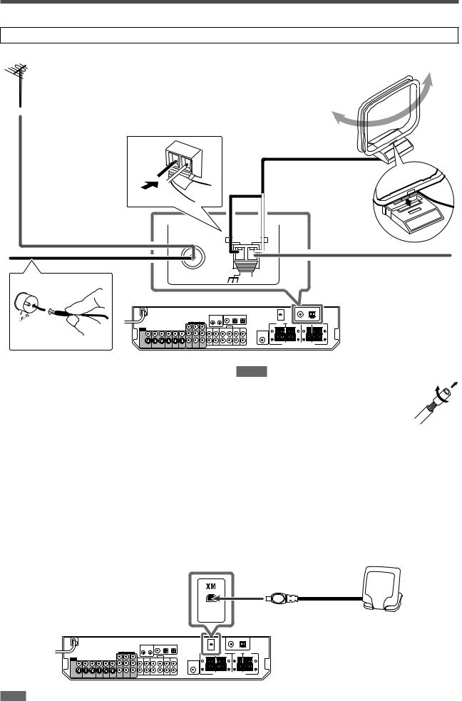
Connecting antennas
Do not connect the AC power plug to the wall outlet until all connections are completed.
7 Connecting FM and AM antennas
AM loop antenna (supplied)
If FM reception is poor, connect an outdoor FM antenna (not supplied).
ANTENNA
FM antenna (supplied)
FM 75
COAXIAL
ANTENNA
AM antenna connection
Connect the AM loop antenna supplied to the AM LOOP terminals.
Connect the white cord to the AM EXT terminal, and connect the black cord to the H terminal.
Turn the loop until you have the best reception.
•If the reception is poor, connect an outdoor single vinyl-covered wire (not supplied) to the AM EXT terminal. Keep the AM loop
antenna connected.
Snap the tabs on the loop into the slots of the base to assemble the AM loop antenna.
AM LOOP
If AM reception is poor, connect an outdoor single vinyl-covered
AM EXT
wire (not supplied).
NOTES
•If the AM loop antenna wire is covered with vinyl, remove the vinyl while twisting it as shown on the right.
• Make sure the antenna conductors do not touch any other terminals, connecting cords and power cord. This could cause poor reception.
FM antenna connection
Connect the FM antenna supplied to the FM 75 Ω COAXIAL terminal as a temporary measure.
Extend the supplied FM antenna horizontally.
•If the reception is poor, connect an outdoor FM antenna (not supplied). Before attaching a 75 Ω coaxial cable with a connector, disconnect the supplied FM antenna.
7 Connecting the XM Connect and Play Digital Antenna
To enjoy XM Satellite Radio, connect the XM Connect and Play Digital Antenna (not supplied) to the XM jack.
XM Connect and Play Digital
Antenna (not supplied)
NOTE
For the best reception:
–Place the XM Connect and Play Digital Antenna near a south-facing window or where “Channel 1” can be heard clearly (see page 17).
–Make sure there is no obstruction between the XM Connect and Play Digital Antenna and the sky.
5
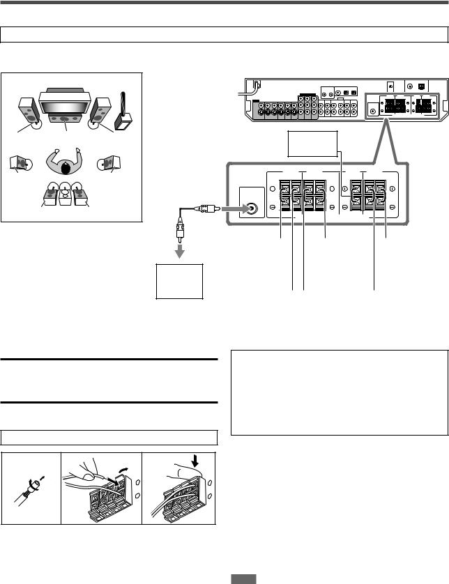
Connecting the speakers
Do not connect the AC power plug to the wall outlet until all connections are completed.
Speaker Layout Diagram
|
|
SW |
L |
C |
R |
LS |
|
RS |
SBL |
(*SB) |
SBR |
Powered subwoofer (SW)
CAUTIONS:
•Use speakers with the SPEAKER IMPEDANCE indicated by the speaker terminals (6 Ω – 16 Ω).
•DO NOT connect more than one speaker to one speaker terminal.
Connecting the speakers
Turn off all components before making connections.
1 |
2 |
1 |
3 |
|
|
2 |
|
+ |
+ |
– |
– |
1Twist and remove the insulation at the end of each speaker cord.
2Open the terminal (1), then insert the speaker cord (2).
•For each speaker, connect the (+) and (–) terminals on the rear panel to the (+) and (–) terminals marked on the speakers.
3Close the terminal.
Center speaker (C)
SURROUND BACK |
SURROUND |
CENTER |
FRONT |
SPEAKERS |
SPEAKERS |
SPEAKER |
SPEAKERS |
RIGHT |
LEFT |
RIGHT |
LEFT |
RIGHT |
LEFT |
SUBWOOFER |
|
|
|
|
|
OUT |
|
|
|
|
|
CAUTION:SPEAKER IMPEDANCE 6 -16
-16
Right surround |
|
|
|
Left |
|
|
Left front |
back speaker |
|
|
|
surround |
|
|
speaker |
(SBR) |
|
|
|
speaker (LS) |
|
|
(L) |
|
|
|
|
|
|
|
|
|
|
|
|
|
|
|
|
*Left surround |
|
|
|
Right |
|
|
Right front |
|
|
|
|||||
back speaker |
|
|
|
surround |
|
|
speaker |
(SBL) |
|
|
|
speaker (RS) |
|
|
(R) |
|
|
|
|
|
|
|
|
|
|
|
|
|
|
|
|
*When using a single speaker for the surround back speaker
You can enjoy the surround sound by one surround back speaker. When using one surround back speaker,
–set “SB OUT” to “<1SPK>” (see page 22) and
–connect the surround back speaker to the left surround back speaker terminal. (No sound comes from the speaker if you connect it to the right surround back speaker terminal.)
Connecting the powered subwoofer
By connecting a subwoofer, you can enhance the bass or reproduce the original LFE signals recorded in digital software.
Connect the input jack of a powered subwoofer to the SUBWOOFER OUT jack on the rear panel, using a cord with RCA pin plugs (not supplied).
• Refer also to the manual supplied with your subwoofer.
After connecting all the speakers and/or a subwoofer, set the speaker setting information properly to obtain the best possible surround effect. For details, see pages 20 to 24.
NOTE
You can place a subwoofer wherever you like since bass sound is non-directional. Normally place it in front of you.
6
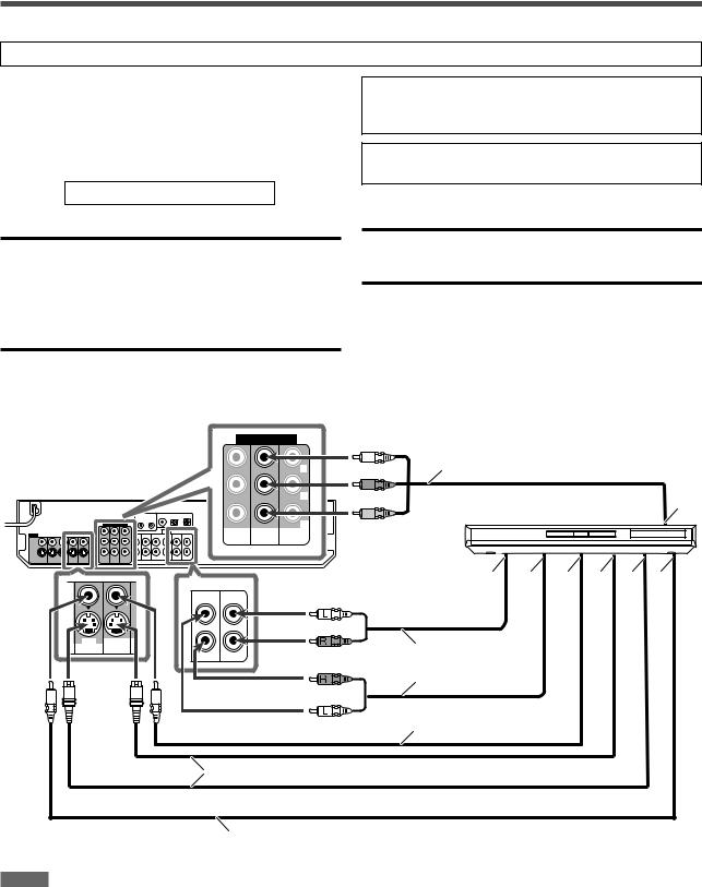
Connecting audio/video components
Do not connect the AC power plug to the wall outlet until all connections are completed.
This receiver is equipped with the following video terminals— composite video, S-video, and component video terminals.
•If your video components have S-video (Y/C-separation) and/or component video (Y, PB, PR) jacks, connect them using an S- video cable (not supplied) or component video cable (not supplied). By using these terminals, you can get better picture quality in the order:
Component > S-video > Composite
IMPORTANT:
This receiver can convert video signals as follows:
•Composite video signals can be converted into both S-video signals and component signals.
•S-video signals can be converted into component signals.
•Component signals cannot be converted.
When converting video signals, there are some points to observe. For details, see “About video signal conversion” on page 10.
Turn off all components before making connections.
•When you connect other components, refer also to their manuals.
DO NOT use a TV through a VCR or a TV with a built-in VCR; otherwise, the picture may be distorted.
CAUTION:
If you connect a sound-enhancing device such as a graphic equalizer between the source components and this receiver, the sound output through this receiver may be distorted.
If your video components have AV COMPU LINK terminal
See also page 35 for detailed information about the connection and the AV COMPU LINK remote control system.
7 Connecting a DVD recorder or DVD player
COMPONENT VIDEO
|
|
Y |
|
|
PB |
|
|
PR |
VCR(DBS) |
DVR/DVD |
MONITOR |
IN |
IN |
OUT |
Green
Blue |
Component video cable (not supplied) |
|
|
Red |
Å |
|
DVD recorder or DVD player |
DVR DVR/DVD
OUT(REC) IN(PLAY)
DVR DVR/DVD
OUT(REC) IN(PLAY)
ı Ç Î ‰ Ï Ì
White
Red
Red |
Stereo audio cable |
|
(not supplied) |
||
|
White
Composite video cable (not supplied)
S-video cable (not supplied)
Composite video cable (not supplied)
NOTES
•When connecting a DVD recorder or DVD player to the component video input jacks, select the component video input mode (DVD VIDEO IN) correctly. If you do not, you cannot view the playback picture on the TV or the AV COMPU LINK remote control system cannot operate properly. See page 25 for details.
•When using a stereo audio cable as the illustration above, set the audio input mode to
“ANALOG.” For details, see “Selecting the analog or digital input mode” on page 12.
•You can enjoy digital sound if using a digital coaxial or optical cable. When shipped from the factory, the digital input terminal setting for a DVD recorder and DVD player is set to use the digital coaxial terminal (DIGITAL IN 1 (DVR/DVD)). For details of digital connection, see page 10.
ÅTo component video output
•Connect Y, PB, and PR correctly. ı To left/right audio channel output
Ç Only for DVD recorder: To left/ right audio channel input
Î To composite video output ‰ To S-video output
Ï Only for DVD recorder: To S-video input
Ì Only for DVD recorder: To composite video input
7

Do not connect the AC power plug to the wall outlet until all connections are completed.
7 Connecting a VCR
COMPONENT VIDEO
Y
PB
Turn off all components before making connections.
• When you connect other components, refer also to their manuals.
Green
Component video cable (not supplied)
Blue
Å
Red
|
|
PR |
VCR(DBS) |
DVR/DVD |
MONITOR |
IN |
IN |
OUT |
VCR
AUDIO |
White |
ı |
Ç |
Î ‰ Ï Ì |
|
|
|
|
|||
VCR |
|
|
|
|
|
OUT(REC) |
IN(PLAY) |
|
|
|
|
|
|
Red |
|
|
|
VCR
OUT(REC) IN(PLAY)
|
Stereo audio cable |
Red |
(not supplied) |
White
Composite video cable  (not supplied)
|
|
|
S-video cable (not supplied) |
|
|
|
|
|
|
|
|
|
|
Composite video cable (not supplied) |
|||||||
|
|
|
|
|
Å To component video output |
|||||
NOTES |
|
|
|
|
|
|||||
• When connecting a VCR to the component video input jacks, select the component |
|
|
• Connect Y, PB, and PR correctly. |
|||||||
video input mode (VCR VIDEO IN) correctly. If you do not, you cannot view the |
|
|
ı To left/right audio channel output |
|||||||
playback picture on the TV or the AV COMPU LINK remote control system cannot |
|
|
Ç To left/right audio channel input |
|||||||
operate properly. See page 25 for details. |
|
|
Î To composite video output |
|||||||
• When using a stereo audio cable as the illustration above, set the audio input mode to |
‰ To S-video output |
|||||||||
“ANALOG.” For details, see “Selecting the analog or digital input mode” on page 12. |
|
|
Ï To S-video input |
|||||||
• You can enjoy digital sound if using a digital coaxial or optical cable. When shipped |
|
|
Ì To composite video input |
|||||||
from the factory, the digital input terminal setting for a VCR is set to use the digital |
|
|
||||||||
|
|
|
|
|
|
|
||||
optical terminal (DIGITAL IN 3 (VCR)). For details of digital connection, see page 10. |
|
|
|
|
|
|||||
7 Connecting a DBS tuner |
|
|
|
|
|
|
|
|||
|
|
Component video cable (not supplied) |
|
|
|
Stereo audio cable |
||||
|
|
|
|
|
|
|
||||
|
|
|
TV/SIRIUS |
DBS |
|
(not supplied) |
||||
|
|
|
VC |
|||||||
|
|
|
L IN |
IN |
OUT(REC) |
|||||
Green |
COMPONENT VIDEO |
|
|
|
|
|
|
|
|
|
|
|
|
|
|
|
|
|
|
||
|
|
|
|
|
|
|
|
|
|
|
Blue |
|
|
|
|
White |
|
|
|
Y |
|
|
|
|
|
|
|
|
|
|
|
|
|
|
Red |
|
PB |
|
R |
Red |
|
|
|
|
|
|
|
|
||
|
|
|
|
|
|
|
|
IN |
IN |
PR |
VIDEO |
Composite video cable (not supplied) |
Å |
ı |
|
OUT |
|||||||
VCR(DBS) |
DVR/DVD |
MONITOR |
|
|
|
||
VIDEO
S-VIDEO
DBS
IN OUT
S-video cable (not supplied)
Ç


ÎDBS tuner
NOTES
•When connecting a DBS tuner to the component video input jacks, select the component video input mode (DBS VIDEO IN) correctly. If you do not, you cannot view the playback picture on the TV. See page 25 for details.
•When using a stereo audio cable as the illustration above, set the audio input mode to “ANALOG.” For details, see “Selecting the analog or digital input mode” on page 12.
•You can enjoy digital sound if using a digital coaxial or optical cable. When shipped from the factory, the digital input terminal setting for a DBS tuner is set to use the digital optical terminal (DIGITAL IN 2 (DBS)). For details of digital connection, see page 10.
Å To left/right audio channel output
ıTo component video output
•Connect Y, PB, and PR correctly. Ç To composite video output
Î To S-video output
8
Do not connect the AC power plug to the wall outlet until all connections are completed.
7 Connecting a TV |
Turn off all components before making connections. |
|
|
||
Connect the TV to the appropriate MONITOR OUT jacks to |
• When you connect other components, refer also to their manuals. |
|
view the playback picture from any other connected video |
||
|
||
components. |
|
COMPONENT VIDEO
|
|
Y |
|
|
PB |
|
|
PR |
VCR(DBS) |
DVR/DVD |
MONITOR |
IN |
IN |
OUT |
Green |
|
Blue |
Component video cable (not supplied) |
Red |
|
TV Å
TV/SIRIUS |
DB |
L IN |
I |
White
|
|
Red |
|
|
MONITOR |
R |
Stereo audio cable |
ı |
|
(not supplied) |
|
|||
OUT |
|
|||
|
|
|
|
|
|
|
|
Ç |
Î |
|
|
S-video cable (not supplied) |
|
|
|
|
Composite video cable (not supplied) |
|
|
NOTES
•When using a stereo audio cable as the illustration above, set the audio input mode to
“ANALOG.” For details, see “Selecting the analog or digital input mode” on page 12.
•You can enjoy digital sound if using a digital coaxial or optical cable. For details of digital connection, see page 10.
7 Connecting a SIRIUS Satellite Radio
ÅTo component video input
•Connect Y, PB, and PR correctly. ı To left/right audio channel output Ç To S-video input
Î To composite video input
5
2 |
3 |
∞
TV/SIRIUS |
DB |
L IN |
I |
R
White
 Stereo audio cable (not supplied) SIRIUS Satellite Radio Red
NOTES
•To connect KT-SR2000 (JVC SIRIUS Satellite Radio) to this receiver, it is required to separately purchase KS-K6013 Home Docking Kit.
•You cannot use a digital audio cable (coaxial or optical) to connect a SIRIUS Satellite Radio to this receiver.
•After connecting a SIRIUS Satellite Radio to the TV IN jacks, change the source name to “SIRIUS.” See page 12 for details.
9
About video signal conversion
This receiver can convert video signals. See the table below about video signal conversion.
|
Video Input |
|
|
|
|
|
Video Output |
|
|
|
|
|
|
|
|
|
Component |
|
|
|
|
|
Component |
|
|
|
|
|
|
||
|
S-video |
|
|
|
|
|
S-video |
|
|
|
|
|
|
|
|
|
|
|
|
|
|
|
|
|
Video (composite) |
|
|
|
|
|
Video (composite) |
|
|
|
|
|
|
||
|
|
|
|
|
|
|
|
To convert composite |
|
|
|
|
|
into component |
|
video signal, set the “DVD VIDEO IN,” “VCR VIDEO IN,” or “DBS
VIDEO IN” to “<S/C>” (see page 25).
•If using composite video cable for connecting to the video input and using S-video cable for connecting to the video output, the video signal is converted into S-video signal automatically. The signal is emitted through the S-video output jacks of MONITOR
OUT, VCR OUT (REC), and DVR OUT (REC).
•Pictures may be distorted if the signals are converted. If this happens, connect the playback source component and TV using the cords of the same type.
•Incoming signal of component can be emitted only through the component output jacks.
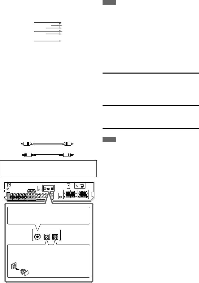
Digital connection
This receiver is equipped with three DIGITAL IN terminals—one digital coaxial terminal and two digital optical terminals.
To reproduce the digital sound, use the digital connection in addition to the analog connection methods described on pages 7 to 9.
Digital coaxial cable (not supplied)
Digital optical cable (not supplied)
Turn off all components before making connections.
•When you connect other components, refer also to their manuals.
When the component has a digital coaxial output terminal, connect it to the 1(DVR/DVD) terminal, using a digital coaxial cable (not supplied).
1(DVR/DVD) 2(DBS) 3(VCR)
When the component has a digital optical output terminal, connect it to the 2(DBS) or 3(VCR) terminal, using a digital optical cable (not supplied).
Before connecting a digital optical cable, unplug the protective plug.
NOTES
•When shipped from the factory, the DIGITAL IN terminals have been set for use with the following components:
– 1(DVR/DVD): |
For DVD recorder or DVD player |
– 2(DBS): |
For DBS tuner |
– 3(VCR): |
For VCR |
If you connect other components, change the digital input (DIGITAL IN) terminal setting correctly. See “Setting the digital input (DIGITAL IN) terminals—DIGITAL IN 1/2/3” on page 25.
•Select the correct digital input mode. See “Selecting the analog or digital input mode” on page 12.
•When you want to operate the connected component (except DBS tuner) using the AV COMPU LINK remote control system (see pages 35 and 36), connect them also as described on pages 7 to 9.
Connecting the power cord
When all the audio/video connections have been made, connect the AC power plug to the wall outlet. Make sure that the plugs are inserted firmly. The standby lamp lights in red.
CAUTIONS:
•Do not touch the power cord with wet hands.
•Do not alter, twist or pull the power cord, or put anything heavy on it, which may cause fire, electric shock, or other accidents.
•If the cord is damaged, consult a dealer and have the power cord replaced with a new one.
NOTES
•Keep the power cord away from the connecting cables and the antenna. The power cord may cause noise or screen interference.
•The preset settings such as preset channels and sound adjustment may be erased in a few days in the following cases:
–When you unplug the power cord.
–When a power failure occurs.
•When you unplug the power cord with the receiver on and connect the power cord again, the receiver enters standby mode.
10
USB connection
This receiver is equipped with a USB terminal. You can enjoy sound reproduced through your PC.
When you connect your PC for the first time, follow the procedure below.
•Remember you cannot send any signal or data to your PC from this receiver.
IMPORTANT:
Check if your PC equipped with the CD-ROM drive is running on Windows® 98 SE*, Windows® Me*, Windows® 2000* or Windows® XP* and prepare its CD-ROM.
Preparation
1.Turn on your PC.
•If the PC has been turned on, quit all the applications now running.
2.Turn on the receiver, and select the source as “USB.”
3.Set the volume to minimum.
IMPORTANT:
Always set volume to “0” when connecting or disconnecting other equipment.
4.Connect the receiver to the PC using a USB cable (not supplied).
USB
USB cable
(not supplied)
PC |
• Use “USB series A plug to B plug” cable when connecting.
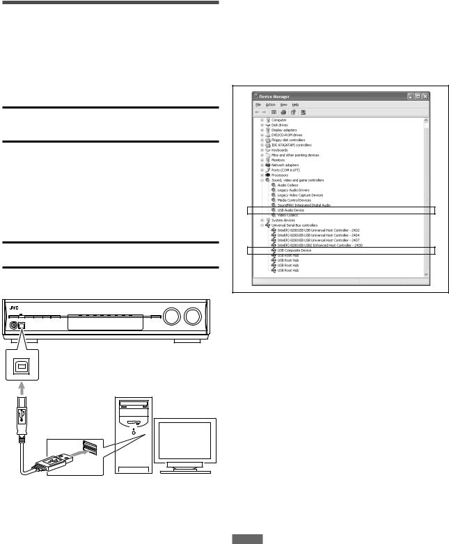
How to install the USB drivers
The following procedure is described using the English version of
WindowsR XP. If your PC is running on a different version of operation system or language, the screens shown on your PC's monitor will differ from the ones used in the following procedure.
1.The USB drivers are installed automatically.
•If the USB drivers are not installed automatically, install the
USB drivers by following the instructions on the PC’s monitor.
2.Check if the drivers are correctly installed.
1.Open the Control Panel on your PC: Select [Start] = [Control Panel].
2.Select [System] = [Hardware] = [Device Manager] =
[Sound, video and game controllers] and [Universal Serial Bus controllers].
•The following window appears, and you can check whether the drivers are installed.
Now the PC is ready for playback through the USB connection.
After installation is completed, you can use your PC as the playback source. The PC automatically recognizes the receiver whenever the USB cable is connected between the PC and the receiver while the receiver is turned on.
•When not using the PC as the playback source, disconnect the transmitter or the USB cable.
To play back sounds on the PC, refer to the manuals supplied with the sound reproduction application installed in the PC. Start the application after the USB device is recognized.
If no sound comes from the speakers, check the following items:
–check if the USB device is recognized properly.
–check if the playback software in your PC is compatible with the
USB device.
–open the Control Panel on your PC, select [Sounds and Audio
Devices] = [Audio] tab = [Sound playback] = [Default device], and check if [Default device] is set to [USB Audio DAC].
–select “USB” as the source.
–connect the USB cable correctly.
NOTES
•DO NOT turn off the receiver or disconnect the USB cable while installing the drivers and for several seconds while your PC is recognizing the receiver.
•If your PC does not recognize the receiver, disconnect the USB cable and connect it again. If it does not work yet, restart
Windows®.
•The installed drivers can be recognized only when the USB cable is connected between the receiver and your PC.
•The sound may not be played back correctly—interrupted or degraded—due to your PC settings and PC specifications.
•Use a USB cable (version 1.1 or later). Recommended cord length is 1.5 m.
*Microsoft®, Windows® 98 SE, Windows® Me, Windows® 2000, and Windows® XP are registered trademarks of Microsoft corporation.
11
Basic operations
1 |
|
2 |
2 |
3 |
Source lamps |
|
|
||
|
|
1 |
|
|
|
|
2 |
|
|
|
|
3 |
|
|
1 |
2 |
3 |
|
|
4 |
5 |
6 |
|
|
7 |
8 |
9 |
|
|
10 |
0 |
10 |
|
|
1 Turn on the power
Press  STANDBY/ON (or
  AUDIO on the remote control).
The standby lamp goes off and the source lamp of the current source lights in red.
Current source name appears.
ANALOG |
AUTO SURR |
TUNED STEREO AUTO MUTING |
L R
S.WFR
MHz
To turn off the power (into standby)
Press  STANDBY/ON (or
  AUDIO on the remote control) again.
The standby lamp lights in red.
NOTE
A small amount of power is consumed in standby mode. To turn the power off completely, unplug the AC power cord.
2 Select the source to play
On the front panel:
Turn SOURCE SELECTOR until the source name you want appears on the display.
The source lamp corresponding to the selected source lights in red.
•As you turn SOURCE SELECTOR, the source changes as follows:
ANALOG |
AUTO SURR |
TUNED STEREO AUTO MUTING |
L |
R |
|
S.WFR
MHz
DVR/DVD
 VCR
VCR 
 DBS
DBS

TV (SIRIUS*1)
 USB
USB
 XM
XM

FM 
 AM
AM
 (Back to the beginning)
DVR/DVD*2: Select this for the DVD recorder or DVD player.
VCR*2: |
Select this for the VCR. |
DBS*2: |
Select this for the DBS tuner. |
TV*1,2: |
Select this for the TV. |
SIRIUS*1: |
Select this for the SIRIUS Satellite Radio. |
USB: |
Select this for the PC component. |
XM: |
Select this for the XM Satellite Radio. |
FM: |
Select this for an FM broadcast. |
AM: |
Select this for an AM broadcast. |
From the remote control:
Press one of the source selecting buttons.
•For “FM” and “AM,” press FM/AM. Each time you press FM/AM, the mode alternates between “FM” and “AM.”
*1 Changing the source name of TV/SIRIUS input
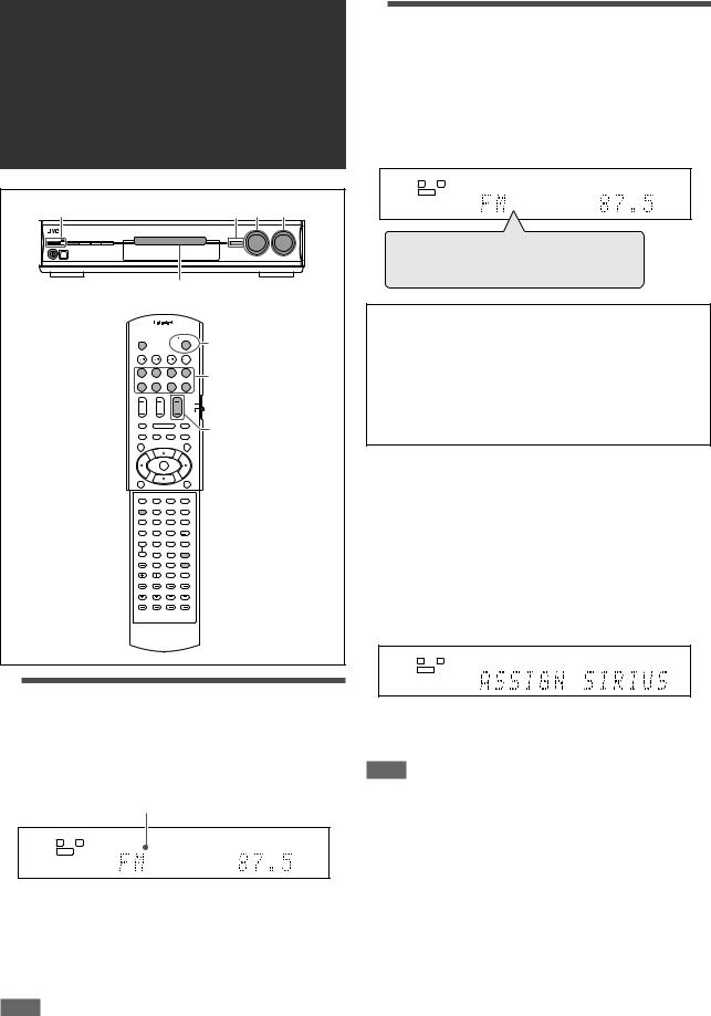
On the front panel only:
Press SET when “TV” is selected as the source.
• “ASSIGN SIRIUS” appears on the display for a while.
ANALOG |
AUTO SURR |
L |
R |
S.WFR
•When you change the source name to “TV,” press SET when
“SIRIUS” is selected as the source. “ASSIGN TV” appears on the display for a while.
NOTE
When you change the source name to “SIRIUS,” you cannot select “TV” as the source.
*2 Selecting the analog or digital input mode
You need to select the proper input mode according to the connection method (analog or digital) on pages 7 to 10.
•In case of digital connection, you also need to select the correct digital input terminal. (See “Setting the digital input (DIGITAL IN) terminals—DIGITAL IN 1/2/3” on page 25.)
•“DIGITAL AUTO” and “ANALOG” setting are memorized for each source.
12

From the remote control ONLY:
Press ANALOG/DIGITAL to select the analog or digital input mode.
•Each time you press the button, the input mode changes as follows:
AUTO SURR
DIGITAL AUTO |
L C |
R |
DIGITAL |
S.WFR |
LFE |
LS |
RS |
DIGITAL AUTO  DOLBY DIGITAL
DTS  ANALOG
  (Back to the beginning)
DIGITAL AUTO: Select for the digital input mode. The receiver automatically detects the incoming signal format, then the digital signal format indicator (LINEAR PCM,


 ,
,  , or
, or  96/24) for the detected signal lights up.
DOLBY DIGITAL*3: Select to play back software encoded with Dolby Digital.
DTS*3: Select to play back software encoded with DTS.
ANALOG: Select for the analog input mode. The ANALOG indicator lights up on the display.
Initial setting: DIGITAL AUTO
*3 If the following symptoms occur while playing Dolby Digital or
DTS software with “DIGITAL AUTO” selected, select “DOLBY DIGITAL” or “DTS.”
•Sound does not come out at the beginning of playback.
•Noise comes out while searching for or skipping chapters or tracks.
Ex.: When “DOLBY DIGITAL” is selected:
AUTO SURR
DIGITAL AUTO |
L C |
R |
DIGITAL |
S.WFR |
LFE |
LS |
RS |
NOTES
•You cannot select the digital input mode when selecting “FM,” “AM,” or “SIRIUS” as the source.
•The input mode is fixed to “DIGITAL AUTO” when selecting
“USB” or “XM” as the source.
•When you turn off the power or select another source,
“DOLBY DIGITAL” or “DTS” is canceled and the digital mode is automatically reset to “DIGITAL AUTO.”
The following digital signal format indicators on the display indicate what type of signal comes into the receiver.
|
|
|
|
Lights up when Linear PCM signal comes in. |
|
|
|
: |
• Lights up when Dolby Digital signal comes |
|
|
|||
|
|
|||
|
|
|
|
in. |
•Flashes when “DOLBY DIGITAL” is selected for any software other than Dolby Digital.
:• Lights up when conventional DTS signal comes in.
•Flashes when “DTS” is selected for any software other than DTS.
96/24: Lights up when DTS 96/24 signal comes in.
NOTE
When “DIGITAL AUTO” cannot recognize the incoming signal, no digital signal format indicator lights up on the display.
3 Adjust the volume
To increase the volume, turn MASTER VOLUME control clockwise (or press VOLUME + on the remote control).
To decrease the volume, turn MASTER VOLUME control counterclockwise (or press VOLUME – on the remote control).
•When you adjust the volume, the volume level indication appears on the display for a while.
ANALOG |
AUTO SURR |
L |
R |
S.WFR
CAUTION:
Always set the volume to the minimum before starting any sources. If the volume is set at its high level, the sudden blast of sound energy can permanently damage your hearing and/or ruin your speakers.
NOTE
The volume level can be adjusted within the range of “0” (minimum) to “50” (maximum).
Listening with headphones
You can enjoy not only stereo software but also multi-channel software through the headphones. (Sounds are down-mixed to the front channels while playing multi-channel software.)
Connect a pair of headphones to the PHONES jack on the front panel to activate the HEADPHONE mode.
The HEADPHONE indicator lights up on the display.
•You can also enjoy the Surround/DSP mode through the headphones—3D HEADPHONE mode. For details, see page 31.
•Disconnecting a pair of headphones from the PHONES jack cancels the HEADPHONE (or 3D HEADPHONE) mode and activates the speakers.
CAUTION:
Be sure to turn down the volume:
•Before connecting or putting on headphones, as high volume can damage both the headphones and your hearing.
•Before removing headphones, as high volume may output from the speakers.
13
Loading...