


 Loading...
HOME CINEMA CONTROL CENTER
RX-E11S
INSTRUCTIONS
LVT1301-010A
[US, UN, UX]
Warnings, Cautions, and Others
Caution–– STANDBY/ON button!
Disconnect the mains plug to shut the power off completely.
The  STANDBY/ON button in any position does not disconnect the mains line. The power can be remote controlled.
CAUTION
To reduce the risk of electrical shocks, fire, etc.:
1.Do not remove screws, covers or cabinet.
2.Do not expose this appliance to rain or moisture.
CAUTION
•Do not block the ventilation openings or holes.
(If the ventilation openings or holes are blocked by a newspaper or cloth, etc., the heat may not be able to get out.)
•Do not place any naked flame sources, such as lighted candles, on the apparatus.
•When discarding batteries, environmental problems must be considered and local rules or laws governing the disposal of these batteries must be followed strictly.
•Do not expose this apparatus to rain, moisture, dripping or splashing and that no objects filled with liquids such as vases, shall be placed on the apparatus.
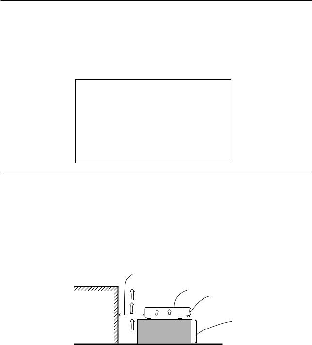
Caution: Proper Ventilation
To avoid risk of electric shock and fire and to protect from damage. Locate the apparatus as follows:
Front: |
No obstructions open spacing. |
Sides: |
No obstructions in 10 cm from the sides. |
Back: |
No obstructions in 15 cm from the back. |
Bottom: |
No obstructions, place on the level surface. |
In addition, maintain the best possible air circulation as illustrated.
Spacing 15 cm or more
RX-E11S
Wall or obstructions
Front
Stand height 15 cm or more
Floor
G-1

Table of Contents
Parts identification ................................................ |
2 |
Getting started ...................................................... |
4 |
Before Installation .................................................................. |
4 |
Checking the supplied accessories ....................................... |
4 |
Putting batteries in the remote control ................................... |
4 |
Setting the voltage selector ................................................... |
4 |
Connecting the FM and AM antennas ................................... |
5 |
Connecting the speakers ....................................................... |
6 |
Connecting video components .............................................. |
7 |
Connecting the power cord .................................................... |
9 |
Basic operations ................................................. |
10 |
1 Turn on the power ............................................................ |
10 |
2 Select the source to play .................................................. |
10 |
3 Adjust the volume ............................................................ |
11 |
Selecting the digital decode mode ....................................... |
11 |
Adjusting the subwoofer audio position ............................... |
12 |
Turning off the sounds temporarily ...................................... |
12 |
Changing the display brightness .......................................... |
12 |
Turning off the power with the Sleep Timer ......................... |
13 |
Basic settings ...................................................... |
14 |
Setting the speaker information automatically |
|
—Smart Surround Setup ............................................... |
14 |
Basic setting items ............................................................... |
15 |
Operating procedure ............................................................ |
16 |
Setting the speakers ............................................................ |
16 |
Setting bass sound .............................................................. |
17 |
Setting the virtual surround back speaker—VIRTUAL SB ... |
18 |
Selecting the main or sub channel—DUAL MONO ............. |
18 |
Using the Midnight mode—MIDNIGHT M. ........................... |
18 |
Setting the digital input (DIGITAL IN) terminals |
|
—DIGITAL IN1/2/3 ......................................................... |
19 |
Setting Auto Surround—AUTO SURRND ............................ |
19 |
Sound adjustments ............................................. |
20 |
Basic adjustment items ........................................................ |
20 |
Operating procedure ............................................................ |
20 |
Adjusting speaker output level ............................................. |
21 |
Adjusting the sound parameters for the |
|
Surround/DSP modes ................................................... |
21 |
Adjusting the bass sounds ................................................... |
22 |
Adjusting the equalization patterns |
|
—D EQ 63Hz/250Hz/1kHz/4kHz/16kHz ........................ |
22 |
Tuner operations ................................................. |
23 |
Setting the AM tuner interval spacing .................................. |
23 |
Tuning in to stations manually .............................................. |
23 |
Using preset tuning .............................................................. |
23 |
Selecting the FM reception mode ........................................ |
24 |
Creating realistic sound fields ........................... |
25 |
Reproducing theater ambience ........................................... |
25 |
Introducing the Surround modes ......................................... |
25 |
Introducing the DSP modes ................................................. |
27 |
Using the Surround/DSP modes ......................................... |
28 |
AV COMPU LINK remote control system .......... |
30 |
Operating other JVC products ........................... |
32 |
Operating other manufacturers’ products ........ |
34 |
Troubleshooting .................................................. |
37 |
Specifications ...................................................... |
38 |
1

Parts identification
Parts identification |
Remote control |
|
|
|
|||||
See pages in parentheses for details. |
|
|
|||||||
|
|
|
|
||||||
|
|
1 |
OPEN/CLOSE button* (33) |
|
|
||||
|
|
2 |
Standby/on buttons (10, 32 – 36) |
|
|
||||
|
|
|
|
AUDIO, DVR/DVD |
, VCR |
, DBS |
, TV |
||
|
|
3 |
Source selecting buttons (10, 23, 32, 34 – 36) |
||||||
|
|
|
DVR/DVD, VCR, DBS, TV, FM, AM |
|
|
||||
|
|
4 |
TV VOL (volume) +/– button (32, 34) |
|
|||||
|
|
5 |
CHANNEL +/– button (32 – 36) |
|
|
||||
|
|
6 |
• |
Operating buttons for video components (32, 33, 35, 36) |
|||||
|
|
|
|
4, 3, ¢, 1, 7, 8, ¡ |
|
|
|||
|
|
|
• |
Operating buttons for tuner (23, 24) |
|
||||
|
|
|
|
(TUNING, FM MODE, TUNING 9, MEMORY |
|||||
|
|
7 |
Operating buttons for DVD recorder or DVD player* (33) |
||||||
|
|
|
TOP MENU, MENU, cursor buttons (3, 2, 5, ∞), ENTER, |
||||||
|
|
|
ON SCREEN |
|
|
|
|||
|
|
8 |
SMART SURROUND SETUP button (14) |
|
|||||
|
|
9 |
Operating buttons for DVD recorder or DVD player* (33) |
||||||
|
|
|
AUDIO, SUBTITLE, DVD, ZOOM, HDD, SOUND EFFECT, |
||||||
1 |
|
|
SET UP, |
, VFP, PROGRESSIVE, ANGLE, |
|
||||
|
|
SLIDE EFFECT, RETURN, TITLE/GROUP, CANCEL |
|||||||
|
|
|
|||||||
2 |
|
p SURROUND button (28) |
|
|
|
||||
|
q SOUND button (10 – 12, 18, 21, 22) |
|
|||||||
|
|
|
|||||||
|
|
w Adjusting buttons for speaker and subwoofer output levels |
|||||||
3 |
e |
|
(21) |
|
|
|
|
||
|
FRONT L +/–, FRONT R +/–, CENTER +/–, SURR L +/–, |
||||||||
|
|
||||||||
|
r |
|
|||||||
|
|
SURR R +/–, SUBWFR +/– |
|
|
|||||
|
|
|
|
|
|||||
4 |
t |
e TV/VIDEO button (32, 34) |
|
|
|||||
|
y |
r MUTING button (12) |
|
|
|
||||
5 |
|
t VOLUME +/– button (11) |
|
|
|
||||
|
y Mode selector (10, 32 – 36) |
|
|
||||||
6 |
|
|
DVR, DVD, AUDIO/TV/VCR/DBS |
|
|
||||
|
u • Numeric buttons (24, 32 – 36) |
|
|
||||||
|
|
|
|
||||||
|
|
|
• |
Adjusting buttons (10 – 12, 18, 21, 22) |
|
||||
|
|
|
|
A/D INPUT, DECODE, EFFECT, BASS BOOST, C.TONE, |
|||||
7 |
|
|
|
MIDNIGHT, A.POSITION |
|
|
|||
|
|
|
• TV RETURN button (32) |
|
|
||||
|
|
i • DISPLAY button* (33) |
|
|
|
||||
|
|
|
• DIMMER button (12, 33) |
|
|
||||
8 |
|
o SLEEP button (13) |
|
|
|
||||
|
; REC PAUSE button (33) |
|
|
|
|||||
|
|
|
|
|
|||||
|
|
a TEST TONE button (21) |
|
|
|
||||
|
|
s D.EQ FREQ button (22) |
|
|
|
||||
9 |
|
d D.EQ LEVEL +/– buttons (22) |
|
|
|||||
|
|
|
|
|
|
|
|
||
|
u |
* These buttons can be used for operating a JVC DVD recorder |
|||||||
|
|
||||||||
|
|
or DVD player with the mode selector set to “DVR” or “DVD” |
|||||||
|
|
(see page 33). |
|
|
|
||||
|
i |
If these buttons do not function normally, use the remote control |
|||||||
|
supplied with your DVD recorder or DVD player. Refer also to |
||||||||
|
o |
||||||||
p |
the manuals supplied with the DVD recorder or DVD player for |
||||||||
; |
|||||||||
q |
details. |
|
|
|
|
||||
a |
|
|
|
|
|||||
|
|
|
|
|
|
|
|
||
w |
s |
|
|
|
|
|
|
|
|
|
d |
|
|
|
|
|
|
|
|
|
|
|
To open the cover of the remote |
|
|
||||
|
|
|
control, push here then slide |
|
|
||||
|
|
|
downward. |
|
|
|
|
||
2
See pages in parentheses for details.
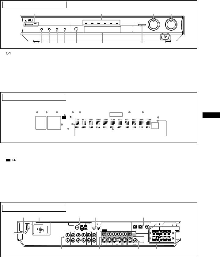
Front panel |
|
|
|
|
|
|
|
|
|
|
||
1 |
|
|
|
|
|
|
2 |
|
|
|
3 |
4 |
|
|
|
|
|
|
|
|
|
|
|
SOURCE |
MASTER |
RX-E11 |
HOME |
CINEMA CONTROL CENTER |
|
|
|
|
|
|
|
|
SELECTOR |
VOLUME |
|
|
|
|
|
|
|
|
MULTI JOG |
|
|||
|
|
|
|
|
DVR / DVD |
VCR |
DBS |
TV |
FM |
AM |
|
|
STANDBY / ON |
|
|
|
|
|
|
|
|
|
SET / TUNER PRESET |
|
|
|
DIMMER |
SETTING |
ADJUST |
SURROUND |
|
|
|
|
|
|
|
|
|
|
|
|
|
|
|
|
|
|
|
PHONES |
|
|
5 6 7 8 |
9 |
|
p |
|
|
q |
w |
|
|||
1 |
|
STANDBY/ON button and standby lamp (10, 23) |
7 |
ADJUST button (20, 23) |
|
2 |
Source lamps |
8 |
SURROUND button (29) |
||
|
DVR/DVD, VCR, DBS, TV, FM, AM |
9 |
Remote sensor (4) |
||
3 |
• |
SOURCE SELECTOR (10, 24) |
p Display window (see below) |
||
|
• |
MULTI JOG (16, 20, 24, 29) |
q • |
SET button (16, 20) |
|
4 |
MASTER VOLUME control (11) |
|
• |
TUNER PRESET button (24) |
|
5 |
DIMMER button (12) |
w PHONES jack (11) |
|||
6 |
SETTING button (16, 23) |
|
|
|
|
Display window
1 |
|
|
2 |
3 4 |
|
5 6 |
|
|
7 |
8 |
9 |
0 |
|||||||||||||||||||
|
|
|
|
|
|
|
|
|
|
|
|
|
|
|
|
|
|
|
|
|
|
|
|
|
|
|
|
|
|
|
|
|
|
|
|
|
|
|
|
|
|
|
|
|
|
|
|
|
|
|
|
|
|
||||||||||
|
|
|
C.TONE |
VIRTUAL SB |
|
AUDIO . BASS TA NEWS INFO RDS TUNED ST AUTO MUTING SLEEP AUTO MODE |
|
|
|||||||||||||||||||||||
|
|
|
|
|
|
||||||||||||||||||||||||||
LPCM |
|
|
|
L |
|
C R |
|
|
PL |
|
|
|
|
|
|
|
|
|
|
|
ATT |
|
|
||||||||
|
|
|
|
|
|
|
|
|
|
|
|
|
|
|
|
||||||||||||||||
DOLBY D |
|
|
|
|
|
|
NEO : 6 |
|
|
|
|
|
|
|
|
|
|
|
HP |
||||||||||||
S . |
WFR |
LFE |
|
|
|
|
|
|
|
|
|
|
|
||||||||||||||||||
DTS |
AAC |
|
|
|
|
|
|
|
DSP |
|
|
|
|
|
|
|
|
|
|
|
MHz |
||||||||||
|
|
|
|
|
|
|
|
|
|
|
|
|
|
|
|
|
|||||||||||||||
96 / |
|
|
|
LS SB RS |
AUTO SR |
|
|
|
|
|
|
|
|
kHz |
|||||||||||||||||
24 |
|
|
|
|
|
|
|
|
|
|
|||||||||||||||||||||
|
|
|
|
|
|
|
|
|
|
|
|
|
|
|
|
|
|
|
|
|
|
|
|
|
|
|
|
|
|
|
|
|
|
|
|
|
|
|
|
|
|
|
|
|
|
|
|
|
|
|
|
|
|
|
|
|
|
|
|||||
- |
|
|
|
|
= ~ ! @ |
|
# |
|
|
|
|
|
|
$ % |
|||||||||||||||||
1 |
EQ indicator (22) |
- Digital signal format indicators (11) |
2 |
C.TONE indicator (21) |
LPCM (Linear PCM), DOLBY D (Dolby Digital), DTS, 96/24 |
3 |
VIRTUAL SB indicator (18, 25, 26) |
= Signal and speaker indicators (13) |
4 |
indicator (25) |
~ DSP indicator (26, 27) |
5 |
AUDIO P. (position) indicator (12) |
! AUTO SR (surround) indicator (19) |
6 |
BASS indicator (22) |
@ 3D indicator (26, 27) |
7 |
Tuner operation indicators (23) |
# Main display |
|
TUNED, ST (stereo) |
$ Frequency unit indicators |
8 |
AUTO MUTING indicator (24) |
MHz (for FM station), kHz (for AM station) |
9 |
SLEEP indicator (13) |
% HP (headphones) indicator (11, 26, 27) |
0 |
ATT (attenuator) indicator (22) |
|
Parts identification
Rear panel
1 |
2 |
3 |
4 |
5 |
|
VOLTAGE |
ANTENNA FM 75 |
|
AM LOOP |
|
|
|
|
|
SELECTOR |
|
|
|
|
|||
220V |
110V |
|
|
|
|
|
|
|
230 - |
127V |
AUDIO |
COAXIAL |
AM EXT |
|
AV COMPU LINK |
VIDEO |
|
240V |
|
|
|
|
|
|
|
|
|
L |
|
|
|
|
|
|
|
|
R |
|
|
|
|
|
|
|
|
DVR |
DVR/DVD |
OUT |
VCR IN |
DBS |
TV |
DVR |
DVR/DVD |
|
OUT (REC) IN (PLAY) |
(REC) |
(PLAY) |
IN |
IN |
OUT (REC) |
IN (PLAY) |
|
67
3(VCR) |
2(DBS) |
1(DVR/DVD) |
CAUTION:SPEAKER |
|
|
|
|
IMPEDANCE 6 - 16 |
|
|
|
FRONT |
CENTER SURROUND |
SPEAKERS |
|
|
RIGHT LEFT |
RIGHT LEFT |
|
VIDEO |
DIGITAL IN |
|
|
|
SUBWOOFER
OUT
OUT |
VCR |
IN |
DBS |
MONITOR |
S-VIDEO |
(REC) |
|
(PLAY) |
IN |
OUT |
|
89
1 |
Power cord (9) |
7 |
VIDEO terminals (7, 8) |
2 |
VOLTAGE SELECTOR (4) |
|
VIDEO (composite video) jacks, S-VIDEO terminals |
3 |
ANTENNA terminals (5) |
|
• Input: DVR/DVD IN (PLAY), VCR IN (PLAY), DBS IN |
4 |
AV COMPU LINK terminals (30) |
|
• Output: DVR OUT (REC), VCR OUT (REC), MONITOR OUT |
5 |
DIGITAL IN terminals (9) |
8 |
SUBWOOFER OUT jack (6) |
|
Coaxial: 1(DVR/DVD) |
9 |
SPEAKERS terminals (6) |
|
Optical: 2(DBS), 3(VCR) |
|
FRONT, CENTER, SURROUND |
6AUDIO jacks (7, 8)
•Input: DVR/DVD IN (PLAY), VCR IN (PLAY), DBS IN, TV IN
•Output: DVR OUT (REC), VCR OUT (REC)
3
Getting started
Getting started
Before Installation
General precautions
•Be sure your hands are dry.
•Turn the power off to all components.
•Read the manuals supplied with the components you are going to connect.
Locations
•Install the receiver in a location that is level and protected from moisture and dust.
•The temperature around the receiver must be between –5˚C and 35˚C.
•Make sure there is good ventilation around the receiver. Poor ventilation could cause overheating and damage the receiver.
Handling the receiver
•Do not insert any metal object into the receiver.
•Do not disassemble the receiver or remove screws, covers, or cabinet.
•Do not expose the receiver to rain or moisture.
The receiver has a built-in cooling fan which operates while the receiver is turned on. Be sure to leave enough ventilation to obtain sufficient cooling effect.
CAUTION:
Do not connect the AC power plug to the wall outlet until all connections are completed.
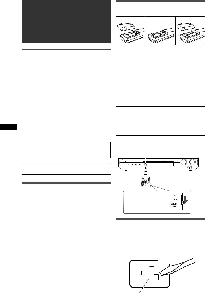
Putting batteries in the remote control
Before using the remote control, put two supplied batteries first.
1 |
2 |
3 |
1Press and slide the battery cover on the back of the remote control.
2Insert batteries.
Make sure to match the polarity: (+) to (+) and (–) to (–).
3 Replace the cover.
If the range or effectiveness of the remote control decreases, replace the batteries. Use two R6(SUM-3)/AA(15F) type dry-cell batteries.
•Supplied butteries are for initial setup. Replace for continued use.
CAUTION:
Follow these precautions to avoid leaking or cracking cells:
•Place batteries in the remote control so they match the polarity:
(+) to (+) and (–) to (–).
•Use the correct type of batteries. Batteries that look similar may differ in voltage.
•Always replace both batteries at the same time.
•Do not expose batteries to heat or flame.
When using the remote control, aim the remote control directly at the remote sensor on the front panel.
Remote sensor
Checking the supplied accessories
Check to be sure you have all of the following supplied accessories. If anything is missing, contact your dealer immediately.
•Remote control (× 1)
•Batteries (× 2)
•AM loop antenna (× 1)
•FM antenna (× 1)
•Digital coaxial cable (× 1)
•AC plug adaptor (× 1) (not supplied for Saudi Arabia)
To operate the receiver, set the mode selector to “AUDIO/TV/VCR/DBS.”
Setting the voltage selector
Before connections, always do the following first if necessary.
Select the correct voltage in VOLTAGE SELECTOR on the rear of the receiver by using a screw driver.
•Check to be sure if the voltage mark is set to the voltage for your area where this unit plugs in.
VOLTAGE
SELECTOR
220V
230 -
240V 127V
Voltage mark
4
Connecting the FM and AM antennas
AM loop antenna (supplied)
If FM reception is poor, connect an outdoor FM antenna (not supplied).
Snap the tabs on the loop into the slots of the base to assemble the AM loop antenna.
FM antenna (supplied) |
ANTENNA |
FM 75 |
AM LOOP |
|
|
|
COAXIAL |
If AM reception is poor, connect |
|
AM EXT |
|
an outdoor single vinyl-covered |
|
wire (not supplied). |
220V  110V
110V
230 -
240V 127V
AM antenna connection |
|
|
|
|
|
|
|
|
|
|
|
|
|
|
|
|
|
|
|
|
|
|
|
|
|
|
|
|
|
|
|
|
|
|
|
|
|
|
|
|
|
|
|
|
|
|
|
|
NOTES |
|
|||||||||||||
Connect the AM loop antenna supplied to the AM LOOP |
• |
If the AM loop antenna wire is covered with vinyl, |
|||||||||||||
terminals. |
|
remove the vinyl while twisting it as shown on the |
|||||||||||||
Turn the loop until you have the best reception. |
|
right. |
|||||||||||||
• If the reception is poor, connect an outdoor single vinyl-covered |
• |
Make sure the antenna conductors do not touch |
|||||||||||||
wire (not supplied) to the AM EXT terminal. Keep the AM loop |
|
any other terminals, connecting cords and power |
|||||||||||||
antenna connected. |
|
cord. This could cause poor reception. |
|||||||||||||
FM antenna connection |
|
|
|
|
|
|
|
|
|
|
|
|
|
|
|
Connect the FM antenna supplied to the FM 75 Ω COAXIAL |
|
|
|
|
|
|
|
|
|
|
|
|
|
|
|
terminal as a temporary measure. |
|
|
|
|
|
|
|
|
|
|
|
|
|
|
|
Extend the supplied FM antenna horizontally. |
|
|
|
|
|
|
|
|
|
|
|
|
|
|
|
• If the reception is poor, connect an outdoor FM antenna (not |
|
|
|
|
|
|
|
|
|
|
|
|
|
|
|
supplied). Before attaching a 75 Ω coaxial cable with a |
|
|
|
|
|
|
|
|
|
|
|
|
|
|
|
connector (IEC or DIN 45325), disconnect the supplied FM |
|
|
|
|
|
|
|
|
|
|
|
|
|
|
|
antenna. |
|
|
|
|
|
|
|
|
|
|
|
|
|
|
|
Getting started
5
Connecting the speakers
Speaker Layout Diagram |
|
|
|
|
|
|
|
|
|
Left front |
Right front |
|
|
|
|
|
|
speaker (L) |
speaker (R) |
|
|
|
|
|
|
|
|
Subwoofer (SW) |
|
||
|
|
Center speaker (C) |
|
|
|
|
|
|
Left surround |
|
|
|
|
Right surround |
|
|
speaker (LS) |
|
|
|
|
speaker (RS) |
|
1 |
2 |
3 |
|
|
|
CAUTION:SPEAKER |
|
|
2 |
1 |
|
|
|
IMPEDANCE 6 |
- 16 |
|
FRONT |
CENTER |
SURROUND |
|
|||
started |
|
|
SPEAKERS |
||||
|
|
RIGHT |
LEFT |
|
RIGHT LEFT |
||
|
|
|
|
||||
|
|
|
|
|
|
|
|
Getting |
|
|
S- |
|
|
|
|
|
|
|
|
|
|
|
|
|
|
SW |
R |
L |
C RS LS |
|
|
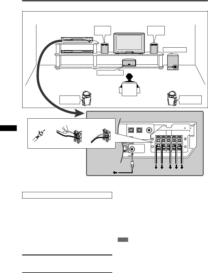
Connecting the front, center, and surround speakers
Turn off all components before making connections.
1Twist and remove the insulation at the end of each speaker cord.
2Press and hold the clamp of the speaker terminal (1), then insert the speaker cord (2).
•For each speaker, connect the (+) and (–) terminals on the rear panel to the (+) and (–) terminals marked on the speakers.
3Release the finger from the clamp.
CAUTIONS:
•Use speakers with the SPEAKER IMPEDANCE indicated by the speaker terminals (6 Ω – 16 Ω).
•DO NOT connect more than one speaker to one speaker terminal.
Connecting the subwoofer
By connecting a subwoofer, you can enhance the bass or reproduce the original LFE signals recorded in digital software.
Connect the input jack of a powered subwoofer to the SUBWOOFER OUT jack on the rear panel, using a cord with RCA pin plugs (not supplied).
• Refer also to the manual supplied with your subwoofer.
After connecting all the speakers and/or a subwoofer, set the speaker setting information properly to obtain the best possible surround effect. For details, see pages 14 to 17.
NOTE
You can place a subwoofer wherever you like since bass sound is non-directional. Normally place it in front of you.
6
Connecting video components
You can use composite video cables or S-video cables for video connection. By using the S-video cable, you can get better picture quality.
•If your video components have digital output terminal, also connect them using the digital terminals explained in “Digital connection” (see page 9). By using these terminals, you can get better sound quality.
CAUTIONS:
•The video signals from one type of input terminals are transmitted only through the video output terminals of the same type. Therefore, if a recording video component and a playing video component are connected to the receiver through the video terminals of different type, you cannot record the picture. In addition, if the TV and a playing video component are connected to the receiver through the video terminals of different type, you cannot view the playback picture on the TV.
•If you connect a sound-enhancing device such as a graphic equalizer between the source components and this receiver, the sound output through this receiver may be distorted.
DO NOT use a TV through a VCR or a TV with a built-in VCR; otherwise, the picture may be distorted.
Turn off all components before making connections.
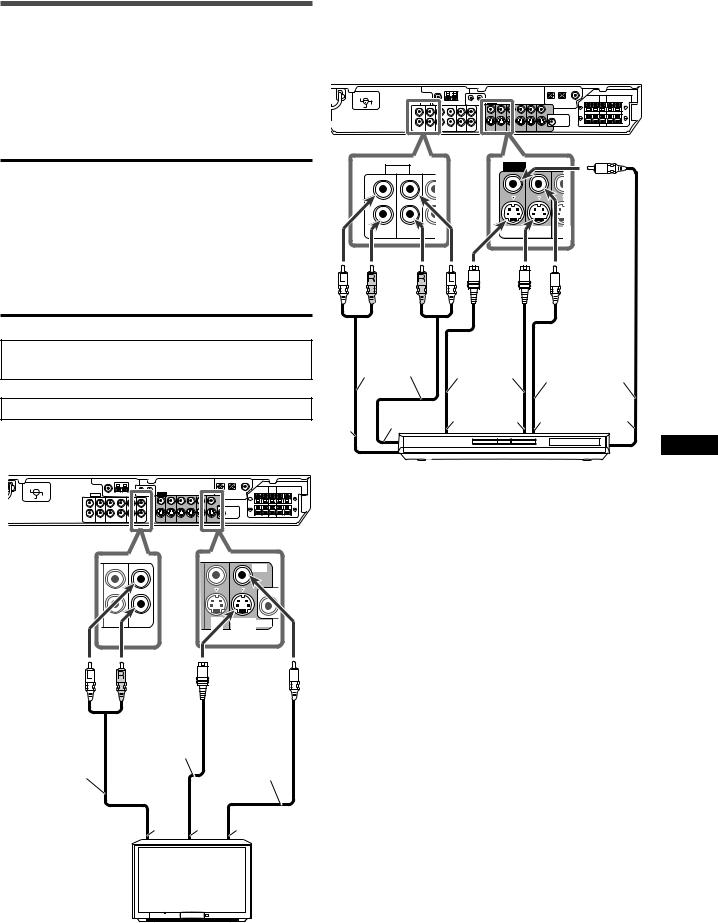
7 Connecting a TV
220V  110V
110V
230 -
240V 127V
|
|
|
VIDEO |
|
DBS |
TV |
DBS |
MONITOR |
S-VIDEO |
IN |
IN |
|||
|
|
IN |
OUT |
|
|
S-video cable |
Composite |
|
|
(not supplied) |
||
Stereo audio cable |
video cable |
||
|
|||
(not supplied) |
|
(not supplied) |
Å ı Ç
TV
Å To audio output
ı To S-video input
Ç To composite video input
7 Connecting a DVD recorder or DVD player
To fully enjoy Dolby Digital and DTS multi-channel software
(including Dual Mono software), connect the DVD recorder or DVD player through the digital input/output terminals (see page
9).
220V  110V
110V
230 -
240V 127V
AUDIO |
VIDEO |
|
L
R
DVR |
DVR/DVD |
OUT |
DVR |
DVR/DVD |
OUT |
OUT (REC) |
IN (PLAY) |
(REC) |
OUT (REC) |
IN (PLAY) |
(REC) |
|
Stereo audio |
|
|
Composite |
|
|
cable (not |
S-video cable |
|
||
|
video cable |
|
|||
|
supplied) |
(not supplied) |
|
||
|
(not supplied) |
||||
|
|
|
|
||
Å |
ı |
Ç |
Î |
‰ |
Ï |
|
|
|
|
||
DVD recorder or DVD player
Å To audio input (DVD recorder only)
ı To audio output
Ç To S-video input (DVD recorder only)
Î To S-video output
‰ To composite video output
Ï To composite video input (DVD recorder only)
Getting started
7
Turn off all components before making connections.
7 Connecting a VCR
220V  110V
110V
230 -
240V 127V
OUT VCR |
IN |
OUT VCR |
IN |
(REC) |
(PLAY) |
(REC) |
(PLAY) |
7 Connecting a DBS tuner
220V  110V
110V
230 -
240V 127V
IN |
DBS |
TV |
IN |
DBS |
MONITOR |
(PLAY) |
IN |
IN |
(PLAY) |
IN |
OUT |
S-video cable (not supplied)
Getting started
|
|
|
Stereo audio cable |
Composite video |
|
S-video cable |
(not supplied) |
||
Stereo audio |
|
cable (not supplied) |
||
cable (not |
(not supplied) |
ı Ç |
|
|
|
|
|
||
supplied) |
|
|
|
|
|
|
|
|
|
|
|
|
Å |
|
|
|
Composite |
|
|
ı |
|
video cable |
DBS tuner |
|
Ç Î |
‰ (not supplied) |
|
||
|
|
|||
|
|
|
Å To audio output |
|
Å |
|
Ï |
ı To S-video output |
|
|
|
Ç To composite video output |
|
|
VCR
Å To audio input ı To audio output
Ç To S-video input
Î To S-video output
‰ To composite video output
Ï To composite video input
8
Digital connection
Turn off all components before making connections.
This receiver is equipped with three DIGITAL IN terminals—a digital coaxial terminal and two digital optical terminals.
To reproduce the digital sound, use the digital connection in addition to the analog connection methods described on pages 7 and 8.
Digital coaxial cable (supplied: 1 cable)
Digital optical cable (not supplied)
220V  110V
110V
230 -
240V 127V
When the component has a digital coaxial output terminal, connect it to the 1(DVR/DVD) terminal, using a digital coaxial cable (supplied).
DIGITAL
When the component has a digital optical output terminal, connect it to the 2(DBS) or 3(VCR) terminal, using a digital optical cable (not supplied).
Before connecting a digital optical cable, unplug the protective plug.
NOTES
•When shipped from the factory, the DIGITAL IN terminals have been set for use with the following components:
– 1(DVR/DVD): For DVD recorder or DVD player
– 2(DBS): |
For DBS tuner |
– 3(VCR): |
For VCR |
If you connect other components, change the digital input
(DIGITAL IN) terminal setting correctly. See “Setting the digital input (DIGITAL IN) terminals—DIGITAL IN1/2/3” on page 19.
•Select the correct digital input mode. See “Selecting the analog or digital input mode” on page 10.
Connecting the power cord
When all the audio/video connections have been made, connect the AC power plug to the wall outlet. Make sure that the plugs are inserted firmly. The standby lamp lights in red.
CAUTIONS:
•Do not plug in before setting the VOLTAGE SELECTOR switch on the rear of the receiver and all connection procedures are complete.
•Do not touch the power cord with wet hands.
•Do not alter, twist or pull the power cord, or put anything heavy on it, which may cause fire, electric shock, or other accidents.
•If the cord is damaged, consult a dealer and have the power cord replaced with a new one.
NOTES
•Keep the power cord away from the connecting cables and the antenna. The power cord may cause noise or screen interference.
•The preset settings such as preset channels and sound adjustment may be erased in a few days in the following cases:
–When you unplug the power cord.
–When a power failure occurs.
•If the wall outlet does not match the AC plug, use the supplied
AC plug adaptor (not supplied for Saudi Arabia).
Getting started
9
Basic operations
Basic operations
1 |
2 |
3 |
1 |
|
|
2 |
|
|
|
When operating the receiver |
|
|
using the remote control, set |
|
3 |
the mode selector to |
|
“AUDIO/TV/VCR/DBS.” |
|
|
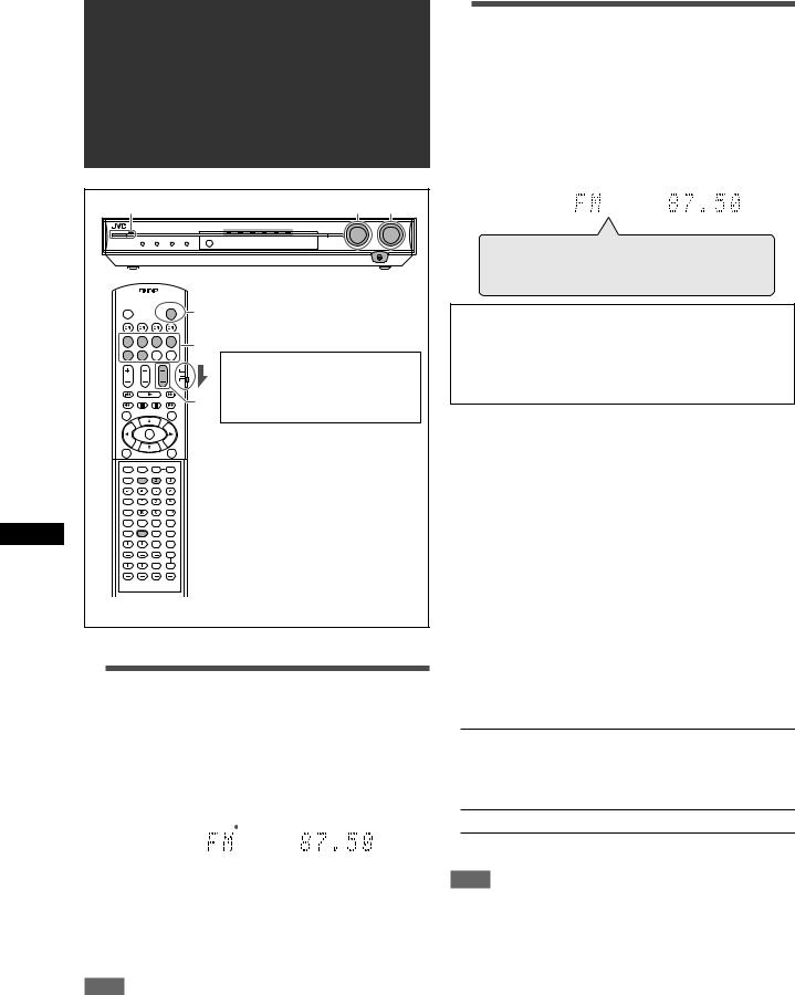
1 Turn on the power
Press  STANDBY/ON (or
  AUDIO on the remote control).
The standby lamp goes off and the source lamp of the current source lights in red.
Current source name appears.
|
|
|
|
|
|
|
|
|
|
EQ C.TONE |
VIRTUAL SB AUDIO P. BASS |
TA |
NEWS INFO RDS TUNED ST AUTO MUTING SLEEP AUTO MODE |
||||||
LPCM |
L |
C |
R |
|
PL |
|
ATT |
||
DOLBY D |
S . WFR LFE |
NEO : 6 |
|
HP |
|||||
DTS AAC |
|
|
|
|
|
DSP 3D |
|
MHz |
|
LS |
SB |
RS |
|||||||
96 / 24 |
AUTO SR |
|
kHz |
||||||
|
|
|
|
|
|
|
|
|
|
To turn off the power (into standby)
Press  STANDBY/ON (or
  AUDIO on the remote control) again.
The standby lamp lights in red.
NOTE
A small amount of power is consumed in standby mode. To turn the power off completely, unplug the AC power cord.
2 Select the source to play
On the front panel:
Turn SOURCE SELECTOR until the source name you want appears on the display.
The source lamp corresponding to the selected source lights in red.
•As you turn SOURCE SELECTOR, the source changes as follows:
EQ C.TONE |
VIRTUAL SB AUDIO P. BASS |
TA NEWS INFO RDS TUNED ST AUTO MUTING SLEEP AUTO MODE |
||||||
LPCM |
L |
C |
R |
|
PL |
ATT |
||
DOLBY D |
S . WFR LFE |
NEO : 6 |
HP |
|||||
DTS AAC |
|
|
|
|
|
DSP 3D |
MHz |
|
LS |
SB |
RS |
||||||
96 / 24 |
AUTO SR |
kHz |
||||||
|
|
|
|
|
|
|
|
|
DVR/DVD (DGT) 
 VCR (DIGITAL)
 DBS (DIGITAL)
 TV (DIGITAL)

FM 
 AM
AM 
 (Back to the beginning)
DVR/DVD (DGT)*: Select the DVD recorder or DVD player.
VCR (DIGITAL)*: |
Select the VCR. |
DBS (DIGITAL)*: Select the DBS tuner. |
|
TV (DIGITAL)*: |
Select the TV. |
FM: |
Select an FM broadcast. |
AM: |
Select an AM broadcast. |
From the remote control:
Press one of the source selecting buttons.
* Selecting the analog or digital input mode
For a component you have connected using both the analog connection and the digital connection methods (see pages 7 to 9), you need to select the correct input mode.
•You can select the digital input only for sources which you have selected digital input terminals for. (See “Setting the digital input (DIGITAL IN) terminals—DIGITAL IN1/2/3” on page 19.)
From the remote control ONLY:
Press SOUND, then press A/D INPUT to select the analog or digital input mode.
•Each time you press A/D INPUT, the input mode alternates between the analog input (“ANALOG”) and the digital input
(“DGTL AUTO”).
DGTL AUTO: Select for the digital input mode. The receiver automatically detects the incoming signal format, then the digital signal format indicator
(LPCM, DOLBY D, DTS, or DTS 96/24) for the detected signal lights up.
ANALOG: Select for the analog input mode.
Initial setting: ANALOG
NOTE
After pressing SOUND, the numeric buttons work for sound adjustments. To use the numeric buttons to operate your target source, press the corresponding source selecting button before operation; otherwise, the remote control may not work as you intend.
10
3 Adjust the volume
To increase the volume, turn MASTER VOLUME control clockwise (or press VOLUME + on the remote control).
To decrease the volume, turn MASTER VOLUME control counterclockwise (or press VOLUME – on the remote control).
•When you adjust the volume, the volume level indication appears on the display for a while.
EQ C.TONE |
VIRTUAL SB AUDIO P. BASS |
TA NEWS INFO RDS TUNED ST AUTO MUTING SLEEP AUTO MODE |
||||||
LPCM |
L |
C |
R |
|
PL |
ATT |
||
DOLBY D |
S . WFR LFE |
NEO : 6 |
HP |
|||||
DTS AAC |
|
|
|
|
|
DSP 3D |
MHz |
|
LS |
SB |
RS |
||||||
96 / 24 |
AUTO SR |
kHz |
||||||
|
|
|
|
|
|
|
|
|
CAUTION:
Always set the volume to the minimum before starting any sources. If the volume is set at its high level, the sudden blast of sound energy can permanently damage your hearing and/or ruin your speakers.
NOTE
The volume level can be adjusted within the range of “0” (minimum) to “50” (maximum).
Listening with headphones
You can enjoy not only stereo software but also multi-channel software through the headphones. (Sounds are down-mixed to the front channels while playing multi-channel software.)
Connect a pair of headphones to the PHONES jack on the front panel to activate the HEADPHONE mode.
The HP (headphone) indicator lights up on the display.
•You can also enjoy the Surround/DSP mode through the headphones—3D HEADPHONE mode. For details, see pages
26 and 27.
•Disconnecting a pair of headphones from the PHONES jack cancels the HEADPHONE (or 3D HEADPHONE) mode and activates the speakers.
CAUTION:
Be sure to turn down the volume:
•Before connecting or putting on headphones, as high volume can damage both the headphones and your hearing.
•Before removing headphones, as high volume may output from the speakers.
Selecting the digital decode mode
If the following symptoms occur while playing Dolby Digital or DTS software with “DGTL AUTO” selected (see page 10), follow the procedure below:
•Sound does not come out at the beginning of playback.
•Noise comes out while searching for or skipping chapters or tracks.
From the remote control ONLY:
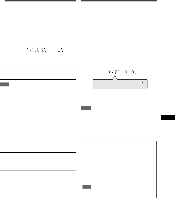
1Press SOUND, then press A/D INPUT to select “DGTL AUTO.”
2Press DECODE to select “DGTL D.D.” or “DGTL DTS.”
•Each time you press the button, the digital decode mode changes as follows:
EQ C.TONE |
VIRTUAL SB AUDIO P. BASS |
TA NEWS INFO RDS TUNED ST AUTO MUTING SLEEP AUTO MODE |
|||||||
LPCM |
L |
|
C |
|
R |
|
PL |
ATT |
|
DOLBY D |
S . WFR LFE |
NEO : 6 |
HP |
||||||
DTS AAC |
|
|
|
|
|
|
DSP 3D |
MHz |
|
LS |
SB |
RS |
|||||||
96 / 24 |
AUTO SR |
kHz |
|||||||
|
|
|
|
|
|
|
|
|
|
DGTL AUTO  DGTL D.D.
DGTL DTS  (Back to the beginning)
•To play back software encoded with Dolby Digital, select “DGTL D.D.”
•To play back software encoded with DTS, select “DGTL DTS.”
NOTES
•When you turn off the power or select another source, “DGTL D.D.” or “DGTL DTS” is canceled and the digital decode mode is automatically reset to “DGTL AUTO.”
•After pressing SOUND, the numeric buttons work for sound adjustments. To use the numeric buttons to operate your target source, press the corresponding source selecting button before operation; otherwise, the remote control may not work as you intend.
The following digital signal format indicators on the display indicate what type of signal comes into the receiver.
LPCM: Lights up when Linear PCM signal comes in.
DOLBY D: • Lights up when Dolby Digital signal comes in.
•Flashes when “DGTL D.D.” is selected for any
software other than Dolby Digital.
DTS: • Lights up when conventional DTS signal comes in.
•Flashes when “DGTL DTS” is selected for any software other than DTS.
DTS 96/24: Lights up when DTS 96/24 signal comes in.
NOTE
When “DGTL AUTO” cannot recognize the incoming signal, no digital signal format indicator lights up on the display.
Basic operations
11
Loading...