


 Loading...
HOME CINEMA CONTROL CENTER
RX-E100RSL
|
|
AUDIO |
|
|
|
|
|
|
|
|
|
|
|
|
|
|
DVD |
STB |
VCR |
TV |
|
|
|
|
|
|
|
|
|
|
|
|
|
|
SLEEP |
TV DIRECT |
|
|
|
|
|
|
|
|
|
|
|
|
|
|
DVD |
STB |
VCR |
TV |
|
|
|
|
|
|
|
|
|
|
|
|
|
ANALOG/DIGITAL |
TAPE |
FM |
AM |
|
|
|
|
|
|
|
|
|
|
|
|
|
INPUT |
|
|
|
|
|
|
|
|
|
|
|
|
|
|
|
|
SOUND |
BASS+ |
CENTER |
|
|
|
|
|
|
|
|
|
|
|
|
|
|
|
1 |
2 |
3 |
|
|
|
|
|
|
|
|
|
|
|
|
|
TEST |
BASS– |
REAR-L |
|
|
|
|
|
|
|
|
|
|
|
|
|
|
|
4 |
5 |
6 |
|
|
|
|
|
|
|
|
|
|
|
|
|
BASS BOOST |
TREBLE+ |
REAR-R |
|
|
|
|
|
|
|
|
|
|
|
|
|
|
|
7 |
8 |
9 |
|
|
|
|
|
|
|
|
|
|
|
|
|
EFFECT |
TREBLE– |
SUBWOOFER |
|
|
|
|
|
|
|
|
|
|
|
|
|
|
|
10 |
0 |
+10 |
|
|
|
|
|
|
|
|
|
|
|
|
|
|
RETURN FM MODE |
100+ |
|
|
|
|
|
|
|
|
|
|
|
|
|
|
|
EON SELECT |
|
|
|
|
|
|
|
|
|
|
|
|
|
|
|
DISPLAY MODE |
|
RDS |
|
|
|
|
|
|
|
|
|
|
|
|
|
|
|
|
|
DVD |
|
|
|
|
|
|
|
|
|
|
|
|
|
DVD MENU |
EON |
|
MENU |
|
|
|
|
|
|
|
|
|
|
|
|
|
PTY( |
ENTER |
|
PTY9 |
|
|
|
|
|
|
|
|
|
|
|
|
|
DSP |
|
|
SURROUND |
|
|
|
|
|
|
|
|
|
|
|
|
|
MODE |
|
|
ON/OFF |
|
|
|
|
|
|
|
|
|
|
|
|
|
|
|
PTY SEARCH |
|
|
|
|
|
|
|
|
|
|
|
|
|
|
TV VOL |
CHANNEL |
VOLUME |
|
|
|
|
|
|
|
|
|
|
|
|
|
|
TV/VIDEO |
DIMMER |
VCR |
MUTING |
STANDBY |
|
|
|
RX-E100R |
HOME CINEMA CONTROL CENTER |
|
|
|
||||
|
CONTROL |
|
|
|
|
|
|
|
||||||||
/REW |
PLAY |
|
FF/ |
TV DIRECT |
|
DVD |
|
|
|
STB |
VCR |
TV |
TAPE |
FM/AM |
|
|
|
|
|
|
|
|
|
|
|||||||||
DOWN |
TUNING |
UP |
STANDBY/ON |
|
|
|
|
|
|
|
|
|
|
|
|
|
REC |
STOP |
|
PAUSE |
|
|
|
|
|
|
|
|
|
|
|
|
|
|
|
|
|
|
CONTROL |
ANALOG |
L |
C |
R |
PRO LOGIC SLEEP |
|
TUNED |
ST AUTO MUTING |
|
|
|
|
|
|
|
|
|
LPCM |
SUBWFR LFE DSP |
|
|
MH |
|
|
|
|||
|
|
|
|
|
|
DOLBY D |
LS |
S |
RS |
DGTL AUTO |
|
|
KH |
INPUT |
SURROUND |
DSP |
|
|
|
|
SETTING |
ADJUST |
DTS |
INPUT ATT |
|
|
VOL |
||||||
|
|
|
|
MEMORY |
|
|
|
|
|
|
|
ANALOG/DIGITAL |
ON/OFF |
MODE |
||
|
|
|
|
|
|
|
|
|
|
|
|
|
|
|
|
MASTER VOLUME |
|
|
|
|
|
|
|
|
|
|
|
|
|
|
INPUT ATT |
|
|
|
|
|
|
|
|
DVD |
|
|
|
STB |
VCR |
TV |
TAPE |
FM/AM |
|
|
|
|
|
|
D I G I T A L |
|
|
|
|
|
|
|
|
|
|
|
|
RM-SRXE100R REMOTE CONTROL |
|
|
|
|
|
|
|
|
|
|
|
|
|
|||
HOME CINEMA CONTROL CENTER |
|
|
|
|
|
|
|
|
|
|
|
|
|
|||
INSTRUCTIONS
For Customer Use:
Enter below the Model No. and Serial No. which are located either on the rear, bottom or side of the cabinet. Retain this information for future reference.
Model No.
Serial No.
LVT0650-003A
[B]
Warnings, Cautions and Others
IMPORTANT for the U.K.
DO NOT cut off the mains plug from this equipment. If the plug fitted is not suitable for the power points in your home or the cable is too short to reach a power point, then obtain an appropriate safety approved extension lead or consult your dealer.
BE SURE to replace the fuse only with an identical approved type, as originally fitted.
If nonetheless the mains plug is cut off ensure to remove the fuse and dispose of the plug immediately, to avoid a possible shock hazard by inadvertent connection to the mains supply.
If this product is not supplied fitted with a mains plug then follow the instructions given below:
IMPORTANT.
DO NOT make any connection to the terminal which is marked with the letter E or by the safety earth symbol or coloured green or green-and-yellow.
The wires in the mains lead on this product are coloured in accordance with the following code:
Blue : Neutral
Brown : Live
As these colours may not correspond with the coloured markings identifying the terminals in your plug proceed as follows:
The wire which is coloured blue must be connected to the terminal which is marked with the letter N or coloured black.
The wire which is coloured brown must be connected to the terminal which is marked with the letter L or coloured red.
IF IN DOUBT - CONSULT A COMPETENT ELECTRICIAN.
CAUTION
To reduce the risk of electrical shocks, fire, etc.:
1.Do not remove screws, covers or cabinet.
2.Do not expose this appliance to rain or moisture.
Caution ––  switch!
Disconnect the mains plug to shut the power off completely. The  switch in any position does not disconnect the mains line. The power can be remote controlled.
CAUTION
•Do not block the ventilation openings or holes.
(If the ventilation openings or holes are blocked by a newspaper or cloth, etc., the heat may not be able to get out.)
•Do not place any naked flame sources, such as lighted candles, on the apparatus.
•When discarding batteries, environmental problems must be considered and local rules or laws governing the disposal of these batteries must be followed strictly.
•Do not use this apparatus in a bathroom or places with water. Also do not place any containers filled with water or liquids (such as cosmetics or medicines, flower vases, potted plants, cups, etc.) on top of this apparatus.
G-1
SAFETY INSTRUCTIONS
“SOME DOS AND DON’TS ON THE SAFE USE OF EQUIPMENT”
This equipment has been designed and manufactured to meet international safety standards but, like any electrical equipment, care must be taken if you are to obtain the best results and safety is to be assured.
Do read the operating instructions before you attempt to use the equipment.
Do ensure that all electrical connections (including the mains plug, extension leads and interconnections between pieces of equipment) are properly made and in accordance with the manufacturer’s instructions. Switch off and withdraw the mains plug when making or changing connections.
Do consult your dealer if you are ever in doubt about the installation, operation or safety of your equipment.
Do be careful with glass panels or doors on equipment.
DON’T continue to operate the equipment if you are in any doubt about it working normally, or if it is damaged in any way–switch off, withdraw the mains plug and consult your dealer.
DON’T remove any fixed cover as this may expose dangerous voltages.
DON’T leave equipment switched on when it is unattended unless it is specifically stated that it is designed for unattended operation or has a standby mode.
Switch off using the switch on the equipment and make sure that your family know how to do this.
Special arrangements may need to be made for infirm or handicapped people.
DON’T use equipment such as personal stereos or radios so that you are distracted from the requirements of traffic safety. It is illegal to watch television whilst driving.
DON’T listen to headphones at high volume as such use can permanently damage your hearing.
DON’T obstruct the ventilation of the equipment, for example with curtains or soft furnishings.
Overheating will cause damage and shorten the life of the equipment.
DON’T use makeshift stands and NEVER fix legs with wood screws — to ensure complete safety always fit the manufacturer’s approved stand or legs with the fixings provided according to the instructions.
DON’T allow electrical equipment to be exposed to rain or moisture.
ABOVE ALL
—NEVER let anyone, especially children, push anything into holes, slots or any other opening in the case -this could result in a fatal electrical shock.;
—NEVER guess or take chances with electrical equipment of any kind — it is better to be safe than sorry!
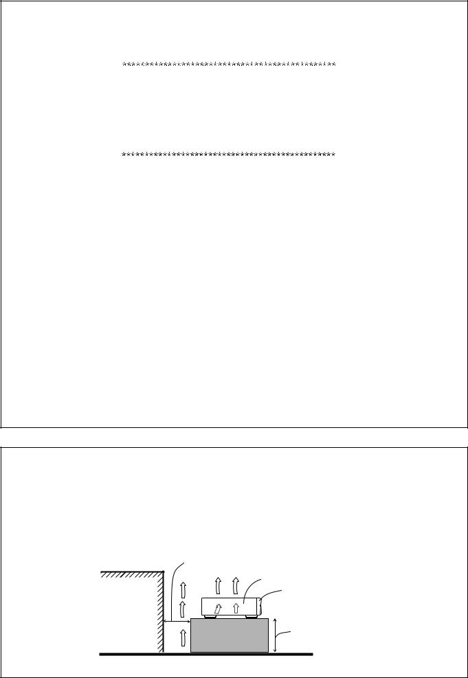
Caution: Proper Ventilation
To avoid risk of electric shock and fire and to protect from damage.
Locate the apparatus as follows:
Front: |
No obstructions open spacing. |
Sides: |
No obstructions in 10 cm from the sides. |
Top: |
No obstructions in 10 cm from the top. |
Back: |
No obstructions in 15 cm from the back |
Bottom: |
No obstructions, place on the level surface. |
In addition, maintain the best possible air circulation as illustrated.
Spacing 15 cm or more
RX-E100RSL
Wall or obstructions
Front
Stand height 15 cm or more
Floor
G-2
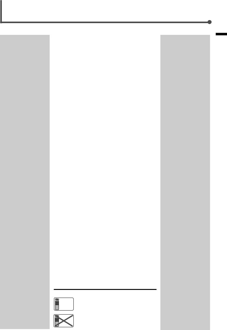
Table of Contents |
|
|
Parts Identification ...................................... |
2 |
|
Getting Started........................................... |
3 |
|
Before Installation ...................................................................... |
3 |
|
Checking the Supplied Accessories ........................................... |
3 |
|
Putting Batteries in the Remote Control .................................... |
3 |
|
Connecting the FM and AM (MW/LW) Antennas ..................... |
4 |
|
Connecting the Speakers ............................................................ |
5 |
|
Connecting Audio/Video Components ....................................... |
7 |
|
Connecting the Power Cord ....................................................... |
9 |
|
Basic Operations ....................................... |
10 |
|
1 Turn On the Power ............................................................... |
10 |
|
2 Select the Source to Play ..................................................... |
10 |
|
3 Adjust the Volume ................................................................ |
10 |
|
Activating TV Direct ................................................................ |
11 |
|
Turning Off the Sounds Temporarily ....................................... |
12 |
|
Turning Off the Power with the Timer ..................................... |
12 |
|
Changing the Display Brightness ............................................. |
12 |
|
Basic Settings........................................... |
13 |
|
Setting the Digital Input Terminals .......................................... |
13 |
|
Selecting the Analogue or Digital Input Mode ........................ |
13 |
|
Setting the Subwoofer Information .......................................... |
15 |
|
Setting the Speakers for DSP Modes ....................................... |
15 |
|
Setting Auto Surround .............................................................. |
18 |
|
Setting TV Direct Mode ........................................................... |
19 |
|
Sound Adjustments.................................... |
20 |
|
Attenuating the Input Signal .................................................... |
20 |
|
Adjusting the Front Speaker Output Balance ........................... |
20 |
|
Reinforcing the Bass ................................................................ |
21 |
|
Adjusting the Tone ................................................................... |
21 |
|
Adjusting the Subwoofer Output Level .................................... |
22 |
|
Tuner Operations ....................................... |
23 |
|
Tuning in Stations Manually .................................................... |
23 |
|
Using Preset Tuning ................................................................. |
24 |
|
Selecting the FM Reception Mode ........................................... |
25 |
|
Using the RDS (Radio Data System) to Receive FM Stations ........... |
26 |
|
Searching for a Program by PTY Codes .................................. |
27 |
|
Switching to a Broadcast Program of |
|
|
Your Choice Temporarily ................................................... |
29 |
|
Creating Realistic Sound Fields ................... |
30 |
|
About Relations between Speaker Layout and DSP Modes ....... |
32 |
|
Using Surround Modes (Remote Control) ............................... |
33 |
|
Using Theatre Surround (Remote Control) .............................. |
35 |
|
Using DAP Modes (Remote Control) ...................................... |
36 |
|
Using Surround Modes (Front Panel) ...................................... |
37 |
|
Using Theatre Surround (Front Panel) ..................................... |
38 |
|
Using DAP Modes (Front Panel) ............................................. |
39 |
|
Mastering Remote Operations .................... |
40 |
|
Troubleshooting ......................................... |
45 |
|
Specifications............................................ |
46 |
|
Remote |
This mark indicates that the remote control CAN |
|
ONLY |
ONLY be used for the operation explained. |
|
Remote |
This mark indicates that only the remote control |
|
NOT |
CANNOT be used for the operation explained. |
|
Contents of Table
1
Parts Identification
Front Panel
1 |
2 |
3 |
|
|
|
|
4 |
|
STANDBY |
|
|
|
RX-E100R |
HOME CINEMA CONTROL CENTER |
|
||
|
|
TV DIRECT |
DVD |
STB |
VCR |
TV |
TAPE |
FM/AM |
STANDBY/ON |
|
|
|
|
|
|
|
|
|
|
|
CONTROL |
ANALOG |
L |
C |
R |
PRO LOGIC |
SLEEP |
RDS |
EON |
TA |
HEWS |
INFO |
TUNED |
ST |
AUTO |
MUTING |
|
|
|
|
|
|
LPCM |
SUBWFR LFE DSP |
|
|
|
|
|
|
|
|
|
MH |
|
|
|
||||
|
|
|
|
|
|
|
|
|
|
|
|
|
|
|
|
||||||
|
|
|
|
DOLBY D |
Ls |
S |
RR |
DGTLAUTO |
|
|
|
|
|
|
|
|
|
KH |
INPUT |
SURROUND |
DSP |
|
SETTING |
ADJUST |
|
DTS |
INPUT ATT |
|
|
|
|
|
|
|
|
|
VOL |
||||||
|
|
MEMORY |
|
|
|
|
|
|
|
|
|
|
|
|
|
|
ANALOG/DIGITAL |
ON/OFF |
MODE |
||
|
|
|
|
|
|
|
|
|
|
|
|
|
|
|
|
|
|
|
|
|
MASTER VOLUME |
|
|
|
|
|
|
|
|
|
|
|
|
|
|
|
|
|
|
|
INPUT ATT |
|
|
D I G I T A L |
|
|
|
DVD |
|
|
|
STB |
|
VCR |
|
|
TV |
|
|
TAPE |
|
|
FM/AM |
|
|
|
|
|
|
|
|
|
|
|
|
|
|
|
|
|
|
||||||
S U R R O U N D |
D I G I T A L |
|
|
|
|
|
|
|
|
|
|
|
|
|
|
|
|
|
|
|
|
5 6 7 |
8 |
9 |
p |
q |
w e |
r |
Remote Control
|
|
|
AUDIO |
|
|
1 |
DVD |
STB |
VCR |
TV |
|
2 |
|
|
SLEEP |
TV DIRECT |
t |
|
|
|
|
||
|
DVD |
STB |
VCR |
TV |
|
3 |
ANALOG/DIGITAL |
TAPE |
FM |
AM |
y |
INPUT |
|
|
|
|
|
4 |
SOUND |
BASS+ |
CENTER |
|
|
|
1 |
2 |
3 |
|
|
5 |
TEST |
BASS– |
REAR•L |
|
|
|
4 |
5 |
6 |
u |
|
6 |
BASS BOOST |
TREBLE+ |
REAR•R |
||
|
7 |
8 |
9 |
|
|
7 |
EFFECT |
TREBLE– |
SUBWOOFER |
|
|
|
10 |
0 |
+10 |
|
|
|
|
RETURN |
FM MODE |
100+ |
|
8 |
|
EON SELECT |
|
i |
|
DISPLAY MODE |
|
RDS |
|||
|
|
|
|
|
|
|
|
|
|
DVD |
|
|
DVD MENU |
EON |
MENU |
|
|
|
|
|
|||
|
PTY( |
PTY9 |
|
||
|
ENTER |
|
|||
9 |
DSP |
|
|
SURROUND |
o |
MODE |
|
|
ON/OFF |
||
p PTY SEARCH
q |
TV VOL |
CHANNEL |
|
VOLUME |
; |
w |
|
|
|
|
a |
e |
TV/VIDEO |
DIMMER |
VCR |
MUTING |
|
|
CONTROL |
|
|||
r |
/REW |
PLAY |
|
FF/ |
|
DOWN |
TUNING |
|
UP |
|
|
|
REC |
STOP |
|
PAUSE |
|
RM-SRXE100R REMOTE CONTROL
HOME CINEMA CONTROL CENTER
See pages in the parentheses for details.
Front Panel
1  STANDBY/ON button and STANDBY lamp (10) 2 TV DIRECT button (11)
3 Display
4 Source indicators
5 Remote sensor
6 SETTING button (13, 15, 17 – 19)
7 ADJUST button (20 – 22, 37 – 39)
8CONTROL buttons (13 – 25, 37 – 39)
5/ / 2/ 3
9 MEMORY button (24)
pSource selecting buttons (10, 11, 14, 23, 25) DVD, STB, VCR, TV, TAPE, FM/AM
qINPUT ANALOG/DIGITAL button (14) INPUT ATT button (20)
w SURROUND ON/OFF button (32, 37) e DSP MODE button (32, 38, 39)
r MASTER VOLUME  /
/ buttons (10)
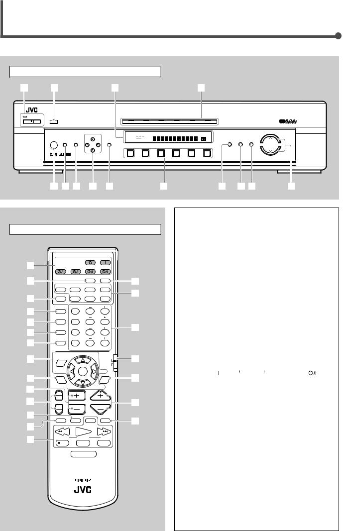
Remote Control
1 POWER buttons (10, 40, 42, 43)
AUDIO  , , DVD
  , STB
, STB  , VCR
, VCR  , TV 2 SLEEP button (12, 40)
3 ANALOG/DIGITAL INPUT button (14, 40)
4 SOUND button (21, 34 – 36, 40)
5 TEST button (33 – 35, 40)
6 BASS BOOST button (21, 40)
7 EFFECT button (35, 36, 40)
8 RDS/DVD MENU mode selector (26 – 28, 41, 42) 9 DSP MODE button (32, 35, 36, 40)
p CHANNEL +/– buttons (41 – 43) q TV VOL +/– buttons (41, 43)
w DIMMER button (12, 40) e TV/VIDEO button (41, 43)
r Operating buttons for audio/video components (23, 41 – 43) t TV DIRECT button (11, 40)
y Source selecting buttons (10, 11, 14, 23, 25, 40, 42, 43) DVD, STB, VCR, TV, TAPE, FM, AM
u• 10 keys for selecting preset channels (25, 41 – 43)
•10 keys for adjusting sound (34 – 36, 41)
•10 keys for operating audio/video components (41 – 43) i RDS/DVD MENU selector (26 – 28, 41, 42)
o SURROUND ON/OFF button (32, 33, 38, 40) ; VOLUME +/– buttons (10, 40)
a MUTING button (12, 40)
2
Getting Started
Before Installation |
Putting Batteries in the Remote Control |
General Precautions
•DO NOT insert any metal object into the unit.
•DO NOT disassemble the unit or remove screws, covers, or cabinet.
•DO NOT expose the unit to rain or moisture.
Locations
•Install the unit in a location that is level and protected from moisture.
•The temperature around the unit must be between 23˚F and 95˚F (–5˚C and 35˚C).
•Make sure there is good ventilation around the unit. Poor ventilation could cause overheating and damage the unit.
Handling the unit
•DO NOT touch the power cord with wet hands.
•DO NOT pull on the power cord to unplug the cord. When unplugging the cord, always grasp the plug so as not to damage the cord.
•Keep the power cord away from the connecting cords and the antenna. The power cord may cause noise or screen interference. It is recommended to use a coaxial cable for antenna connection, since it is well-shielded against interference.
•When a power failure occurs, or when you unplug the power cord, the preset settings such as preset FM/AM (MW/LW) channels and sound adjustments may be erased in a few days.
Checking the Supplied Accessories
Check to be sure you have all of the following supplied accessories. The number in the parentheses indicates the quantity of the pieces supplied.
•Remote Control (1)
•Batteries (2)
•AM (MW/LW) Loop Antenna (1)
•FM Antenna (1)
If anything is missing, contact your dealer immediately.
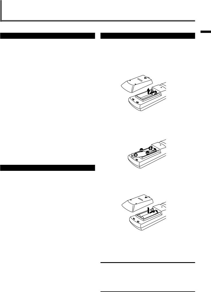
Before using the remote control, put two supplied batteries first.
• When using the remote control, aim the remote control directly at the remote sensor on the unit.
1.On the back of the remote control, remove the battery cover.
2.Insert batteries. Make sure to match the polarity:
(+) to (+) and (–) to (–).
3. Replace the cover.
If the range or effectiveness of the remote control decreases, replace the batteries. Use two R6P(SUM-3)/AA(15F) type dry-cell batteries.
CAUTION:
Follow these precautions to avoid leaking or cracking cells:
•Place batteries in the remote control so they match the polarity: (+) to (+) and (–) to (–).
•Use the correct type of batteries. Batteries that look similar may differ in voltage.
•Always replace both batteries at the same time.
•Do not expose batteries to heat or flame.
Started Getting
3
Getting Started
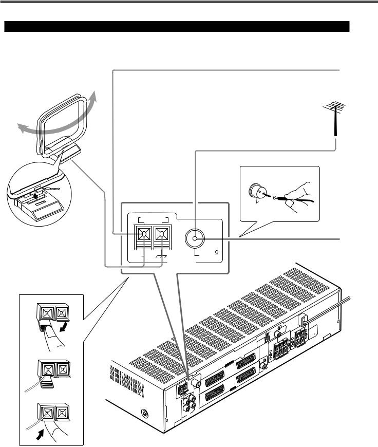
Connecting the FM and AM (MW/LW) Antennas
AM (MW/LW) Loop
Antenna (supplied)
Snap the tabs on the loop into the slots of the base to assemble the AM (MW/LW) loop antenna.
If AM (MW/LW) reception is poor, connect single vinyl-covered wire (not supplied).
If FM reception is poor, connect outdoor FM antenna (not supplied).
B
75
FMCOAXIAL
75
FMCOAXIAL
AM LOOP
FM Antenna (supplied)
AM |
FM 75 |
EXT |
COAXIAL |
|
ANTENNA |
1
2
3
AM |
LOOP |
75 |
|
|
FM |
|
|
COAXIAL |
|
|
ANTENNA |
|
AM |
AUDIO |
||
EXT |
|||
|
|
||
|
|
IN |
|
|
OUT |
(PLAY) |
|
|
|
||
|
(REC) |
|
|
|
TAPE |
||
|
|
|
|
IN |
1 |
|
|
|
DIGITAL |
DIGITAL |
|
|
|
|
|
(DVD) |
|
|
|
|
|
|
SPEAKERS |
|
|
2 |
|
REAR |
LEFT |
|
|
CENTER |
RIGHT |
+ |
|
|
|
DIGITAL |
|||
|
|
|
|
||
|
|
SPEAKER |
|
|
|
|
|
(STB) |
|
|
|
|
|
|
|
|
– |
|
|
|
+ |
|
|
|
|
TV |
|
|
|
|
|
|
– |
|
|
AV |
IN/OUT |
|
|
|
|
|
SUBWOOFEROUT |
|
|
|
|
|
|
|
|
|
|
VCR |
|
|
|
|
|
|
|
STB |
|
|
|
|
AV |
IN |
|
|
|
|
|
|
|
|
|
DVD |
|
|
|
|
|
SPEAKERS LEFT FRONT RIGHT
+ –
+ –
: CAUTION SPEAKER IMPEDANCE 16 8
4
AM (MW/LW) antenna connection
Connect the AM (MW/LW) loop antenna supplied to the AM LOOP terminals.
Turn the loop until you have the best reception.
• If reception is poor, connect an outdoor single vinyl-covered wire to the AM EXT terminal. Keep the AM (MW/LW) loop antenna connected.
FM antenna connection
Connect the FM antenna supplied to the FM 75 Ω COAXIAL terminal as temporary measure.
Extend the supplied FM antenna horizontally.
• If reception is poor, connect an outdoor antenna. Before attaching a 75 Ω coaxial cable (with a standard type connector), disconnect the supplied FM antenna.
Notes:
• If the AM (MW/LW) loop antenna wire is covered with vinyl, remove the vinyl while twisting it as shown to the right.
• Make sure the antenna conductors do not touch any other terminals, connecting cords and power cord.
This could cause poor reception.
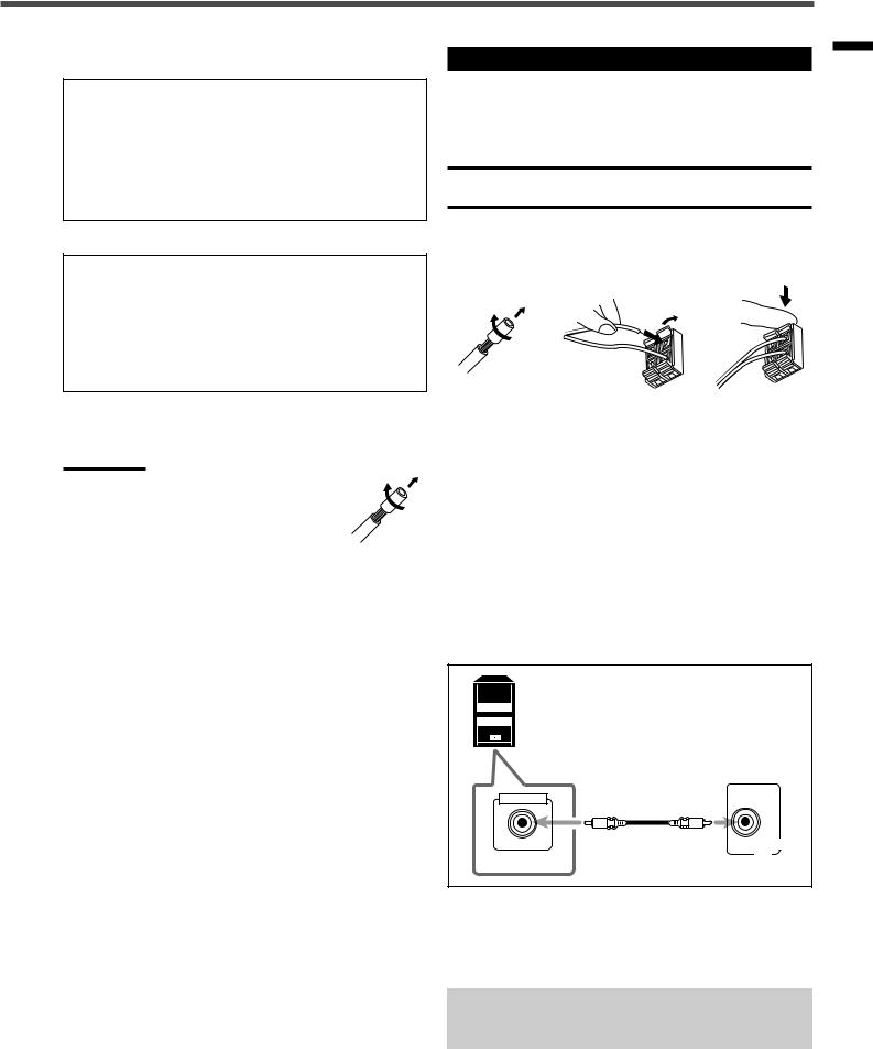
Connecting the Speakers
After connecting the front, center, rear speakers and/or a subwoofer, set the speaker setting information properly to obtain the best possible DSP effect. For details, see page 15.
CAUTION:
Use speakers with the SPEAKER IMPEDANCE indicated by the speaker terminals.
Connecting the front, center, and rear speakers
1 |
2 |
3 |
|
|
|
For each speaker, connect the (+) and (–) terminals on the rear panel to the (+) and (–) terminals marked on the speakers respectively.
1Cut, twist and remove the insulation at the end of each speaker cord (not supplied).
2Open the terminal, then insert the speaker cord.
3Close the terminal.
Connecting the subwoofer speaker
By connecting a subwoofer, you can enhance the bass or reproduce the original LFE signals recorded in the digital software.
Powered subwoofer |
|
(example) |
|
INPUT |
|
|
SUBWOOFER |
HIGH IMPEDANCE |
OUT |
|
Connect the input jack of a powered subwoofer to the SUBWOOFER OUT jack on the rear panel, using a cable with RCA pin plugs (not supplied).
•Refer also to the manual supplied for your subwoofer.
Since bass sound is non-directional, you can place a subwoofer wherever you like. Normally place it in front of you.
Started Getting
5
Getting Started
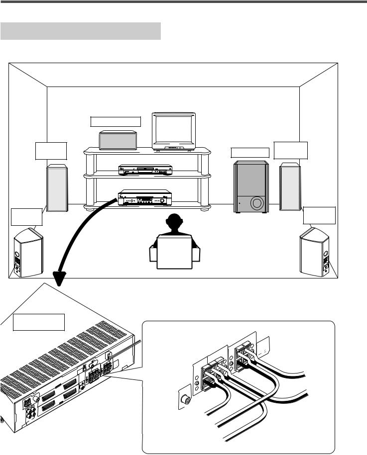
Speaker Layout Diagram
|
Center speaker |
|
Left front |
Subwoofer |
Right front |
speaker |
speaker |
|
Left rear |
|
Right rear |
speaker |
|
speaker |
RX-E100R
|
|
IN |
|
1 |
SPEAKERS |
|
: |
|
|
|
LEFT |
+ |
CAUTION |
||
|
|
DIGITAL |
DIGITAL |
RIGHT |
|||
|
|
|
(DVD) |
FRONT |
|
SPEAKER |
|
|
|
|
|
SPEAKERS |
|
|
IMPEDANCE |
|
|
|
|
|
|
16 |
|
|
|
|
REAR |
LEFT |
+ |
– |
8 |
DIGITAL |
2 |
CENTER |
RIGHT |
+ |
|
|
|
|
|
|
– |
|
|
||
(STB) |
|
SPEAKER |
|
|
|
|
|
|
|
|
|
– |
|
|
|
|
|
|
|
|
|
+ |
|
|
|
|
|
TV |
– |
|
|
|
|
|
|
|
|
|
|
AV |
IN/OUT |
|
|
|
|
|
|
|
SUBWOOFEROUT |
|
|
|
|
|
|
|
|
|
|
|
VCR |
|
|
|
|
|
|
|
|
|
STB |
AM |
LOOP |
|
75 |
|
|
|
|
|
|
FM |
|
|
|
|
|
|
COAXIAL |
|
IN |
|
|
|
ANTENNA |
|
AV |
|
|
AM |
AUDIO |
|
|
|
|
|
EXT |
|
|
DVD |
|
|
|
|
|
IN |
|
|
|
|
|
OUT |
(PLAY) |
|
|
|
|
|
|
|
|
|
|
|
|
(REC)TAPE |
|
|
|
|
|
To subwoofer
CENTER SPEAKER
+ –
REAR RIGHT
SPEAKERS LEFT
 +
+  –
–
SPEAKERS LEFT FRONT RIGHT
+ –
+ –
: CAUTION SPEAKER IMPEDANCE 16
8
To left front speaker
SUBWOOFEROUT |
To left rear speaker |
|
To center speaker
To right front speaker
To right rear speaker
6

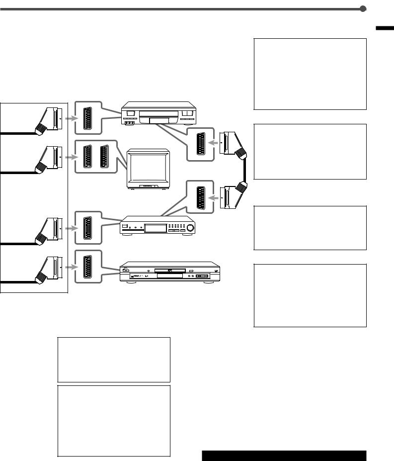
Connecting Audio/Video Components
Turn the power off to all components before connections.
Connecting cords are not supplied with this unit. Use the cords supplied for the other components or purchase them at an audio or electric appliance store.
A |
Coaxial digital cord |
C |
Audio cord |
B |
Optical digital cord |
D |
SCART cable |
Started Getting
Digital connections
|
DIGITAL IN |
DIGITAL 2 |
DIGITAL 1 |
(STB) |
(DVD) |
Before connecting an optical digital cord, unplug the protective plug.
RX-E100R
Analogue connections
AUDIO
LEFT
RIGHT
OUT |
IN |
(REC) |
(PLAY) |
TAPE
AM |
LOOP |
|
75 |
|
|
|
FM |
|
|
|
COAXIAL |
|
|
ANTENNA |
|
EXT |
AUDIO |
|
|
AM |
|
|
|
|
|
IN |
|
|
OUT |
(PLAY) |
|
|
(REC)TAPE |
|
|
C
|
|
|
|
IN |
1 |
|
|
|
DIGITAL |
DIGITAL |
|
|
|
|
|
(DVD) |
|
|
|
|
|
|
SPEAKERS |
|
|
2 |
|
REAR |
LEFT |
|
|
CENTER |
RIGHT |
+ |
|
|
|
DIGITAL |
|
|
|
|
|
(STB) |
SPEAKER |
|
|
|
|
|
|
|
– |
|
|
|
+ |
|
|
|
|
TV |
|
|
|
|
|
|
– |
|
|
AV |
IN/OUT |
|
|
|
|
|
SUBWOOFEROUT |
|
|
|
|
|
|
|
|
|
|
VCR |
|
|
|
|
|
|
|
STB |
|
|
|
|
AV |
IN |
|
|
|
|
|
|
|
|
|
DVD |
|
|
|
|
|
A
B
SPEAKERS |
|
: |
LEFT |
+ |
CAUTION |
RIGHT |
||
FRONT |
|
SPEAKER |
|
|
IMPEDANCE |
|
|
16 |
+ |
– |
8 |
|
||
– |
|
|
DVD Player
COAXIAL
DIGITAL OUT
STANDBY ON
OPTICAL |
STB |
DIGITAL OUT |
|
Illustrations of the input/output terminals are typical examples.
When you connect other components, refer also to their manuals since the terminal names actually printed on the rear vary among the components.
•When shipped from the factory, the DIGITAL IN terminals have been set for use with the following components.
–DIGITAL 1 (coaxial): For DVD player
–DIGITAL 2 (optical): For STB
If you connect other components, change the digital input (DIGITAL IN) terminal setting correctly. See “Setting the Digital Input Terminals” on page 13.
•Select the digital input mode correctly.
See “Selecting the Analogue or Digital Input Mode” on page 13.
If you connect a sound-enhancing device such as a graphic equalizer between the source components and this unit, the sound output through this unit may be distorted.
AUDIO
LEFT
Cassette Deck
RIGHT
OUT IN
TO BE CONTINUED TO THE NEXT PAGE
7
Getting Started
Turn the power off to all components before connections.
Illustrations of the input/output terminals below are typical examples.
When you connect other components, refer also to their manuals since the terminal names actually printed on the rear vary among the components.
D
RX-E100R
AM |
LOOP |
|
75 |
|
|
|
FM |
|
|
|
COAXIAL |
|
|
ANTENNA |
|
EXT |
AUDIO |
|
|
AM |
|
|
|
|
|
IN |
|
|
OUT |
(PLAY) |
|
|
(REC)TAPE |
|
|
|
|
|
IN |
|
1 |
SPEAKERS |
|
: |
|
|
|
|
|
|
LEFT |
+ |
CAUTION |
|
|
||
|
|
|
DIGITAL |
DIGITAL |
RIGHT |
|
|
|||
|
|
|
|
(DVD) |
FRONT |
|
SPEAKER |
|
|
|
|
|
|
|
|
SPEAKERS |
|
|
IMPEDANCE |
|
|
|
|
|
|
|
|
|
16 |
|
|
|
|
|
|
|
REAR |
LEFT |
+ |
– |
8 |
|
|
|
|
2 |
CENTER |
RIGHT |
+ |
|
|
|
|
|
|
|
DIGITAL |
|
|
– |
|
|
|
|
|
|
|
(STB) |
SPEAKER |
|
|
|
|
|
|
|
|
|
|
|
|
– |
|
|
|
|
|
|
|
|
+ |
|
|
|
|
|
|
|
|
|
TV |
|
|
|
|
|
|
|
|
|
|
|
– |
|
|
|
|
|
|
|
AV |
IN/OUT |
|
|
|
|
|
|
|
|
|
|
SUBWOOFEROUT |
|
|
|
|
|
|
|
|
|
|
|
|
|
|
|
|
|
AV IN/OUT |
|
|
VCR |
|
|
|
|
|
|
|
VCR |
TV |
|
|
|
|
|
|
|
|
|
|||
|
|
|
|
|
|
|
|
|
||
|
|
STB |
|
|
|
|
|
|
|
|
|
AV |
IN |
|
|
|
|
|
|
|
|
|
|
|
|
|
|
|
|
|
|
|
DVD |
|
|
|
|
|
|
|
|
|
|
|
|
|
|
|
|
|
|
DVD |
AV IN |
STB |
|
|
|
|
|
|
|
|
|
|
|
SCART Terminal Specifications
*1
|
|
TV |
VCR |
STB |
DVD |
|
AUDIO |
L/R |
V |
V |
V |
V |
*2 |
IN |
Composite |
V |
V |
V |
V |
|
|
− |
|
|
|
|
|
VIDEO |
S-VIDEO |
V |
V |
V |
|
|
|
RGB |
− |
V |
V |
V |
|
AUDIO |
L/R |
V*1 |
V*1 |
|
|
|
OUT |
Composite |
V*1*2 |
V*1*2 |
|
|
*3 |
|
|
− |
|
|
||
|
|
|
|
|
||
VIDEO |
S-VIDEO |
V*2 |
|
|
|
|
|
RGB |
V*2 |
− |
|
|
|
T-V LINK |
|
V*3 |
V*3 |
|
|
|
The signals input from a SCART terminal cannot be output through the same SCART terminal.
The video format of the output video signals are consistent with that of the input video signals. For example, if S-VIDEO signals are input to this unit, no signals other than S-VIDEO signals can be output from this unit. Refer to the manuals supplied with the video components to check the setting of the input/output video signals.
The signals for T-V LINK function are always going through the unit.
8
VCR
TV |
STB
For digital sounds
•To enjoy the DVD software encoded with
Dolby Digital or DTS Digital Surround, connect the DVD player using one of the
DIGITAL IN terminals (see page 7).
•To enjoy the digital sounds, use both the SCART cable connection and the digital connection (see page 7).
•To enjoy the digital broadcast sounds, connect the STB and/or TV to the
DIGITAL IN terminals (see page 7).
For T-V LINK
•You can also use T-V LINK function if you connect the T-V LINK compatible TV and VCR to this unit with a fully wired SCART cables. For details on T-V LINK, see the manuals supplied with the TV and the VCR.
•Connect SCART cable to EXT-2 terminal on your TV for T-V LINK function.
For recording pictures from STB
When you connect a STB and a VCR directly with a SCART cable, you can enjoy recording the pictures from the STB on VCR tapes without menu screens of STB. For details, see the manuals supplied with the
STB.
DVD Player
For an analogue decoder
To watch or record a scrambled program on
STANDBY ON
your VCR, connect the analogue decoder to your VCR and select the scrambled channel on your VCR.
If there is not an appropriate terminal for the decoder on your VCR, connect the decoder to the TV.
Refer also to the manuals supplied with these equipment.
For TV and video format
When the TV is equipped with the plural
SCART terminals, see the manual supplied with the TV to check the available video signals for each terminal, then connect
SCART cable correctly. For details, see the manuals supplied with the TV.
This unit cannot change the video signals
(S-video or Composite). When the video signal of one video component is different from that of the other (for example, one is S- video, the other is Composite), you may not see the pictures appropriately. In this case, unify the video signals of all the video components into S-video or Composite, or you need to switch the video signal of TV
each time you change the source.
Connecting the Power Cord
Before plugging the unit into an AC outlet, make sure that all connections have been made.
Plug the power cord into an AC outlet.
Started Getting
9
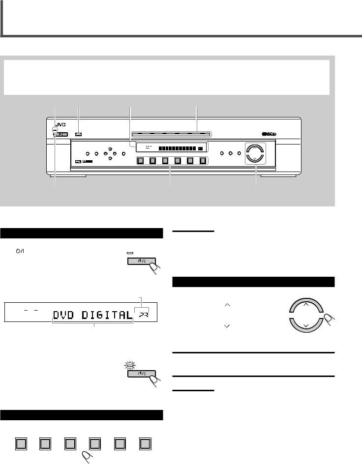
Basic Operations
This manual mainly explains operations using the buttons and controls on the front panel. You can also use the buttons on the remote control if they have the similar names (or marks) as those on the front panel.
If operations using the remote control are different from those using the front panel, they are then explained.
• You can also see “Mastering Remote Operations” on page 40.
STANDBY lamp |
TV DIRECT |
|
Display |
|
|
Source indicators |
|
|
|||||
STANDBY |
|
|
|
|
RX-E100R HOME CINEMA CONTROL CENTER |
|
|
|
|||||
|
TV DIRECT |
|
|
DVD |
STB |
|
VCR |
TV |
TAPE |
|
FM/AM |
|
|
STANDBY/ON |
|
|
|
|
|
|
|
|
|
|
|
|
|
|
|
|
CONTROL |
ANALOG |
L C R PRO LOGIC |
SLEEP |
RDS EON TA HEWS INFO |
TUNED ST |
AUTO MUTING |
|
|
|
|
|
|
|
LPCM |
SUBWFR LFE DSP |
|
|
|
|
MH |
|
|
|
|
|
|
|
|
|
|
|
|
|
|
|
|||
|
|
|
|
DOLBY D |
DGTL AUTO |
|
|
|
|
KH |
INPUT |
SURROUND |
DSP |
|
SETTING |
ADJUST |
|
DTS |
LS S RS INPUT ATT |
|
|
|
|
VOL |
|||
|
|
MEMORY |
|
|
|
|
|
|
ANALOG/DIGITAL ON/OFF |
MODE |
|||
|
|
|
|
|
|
|
|
|
|
|
|
|
MASTER VOLUME |
|
|
|
|
|
|
|
|
|
|
|
INPUT ATT |
|
|
|
D I G I T A L |
|
|
DVD |
STB |
|
VCR |
TV |
TAPE |
|
FM/AM |
|
|
|
|
|
|
|
|
|
|
||||||
|
S U R R O U N D D I G I T A L |
|
|
|
|
|
|
|
|
|
|
|
|
1 |
|
|
|
|
|
|
2 |
|
|
|
|
|
3 |
1 Turn On the Power
Press |
(or AUDIO |
button on the remote |
control).
The STANDBY lamp goes off. The current source indicator lights green. The name of the current source (or station frequency) appears on the display.
STANDBY
STANDBY/ON
Current volume level is shown here
L R
LPCM
DGTL AUTO
VOL


Current source name appears
To turn off the power (into standby)
Press  (or AUDIO
  ) again. The STANDBY lamp lights up.
A small amount of power is consumed in standby mode. To turn the power off completely, unplug the AC power cord.
2 Select the Source to Play
STANDBY
STANDBY/ON
Note:
When you have connected some digital source components using the digital terminals (see page 7), see “Basic Settings” on pages 13, 14, and 15 to finish the digital input terminal setting and digital input mode setting correctly before use.
3 Adjust the Volume
To increase the volume, press and hold
MASTER VOLUME |
(or VOLUME + on the |
remote control). |
MASTER VOLUME |
|
|
To decrease the volume, press and hold |
|
MASTER VOLUME |
(or VOLUME – on the |
remote control). |
|
CAUTION:
Always set the volume to the minimum before starting any source. If the volume is set at its high level, the sudden blast of sound energy can permanently damage your hearing and/or ruin your speakers.
Notes:
•The volume level can be adjusted within the range of “0” (minimum) to “70” (maximum).
•Each time you press the button, the volume level changes by 2 steps from “0” (minimum) to “14” and by 1 step from “14” to “70”
(maximum).
Press one of the source selecting buttons.
DVD |
STB |
VCR |
TV |
TAPE |
FM/AM |
DVD : Select the DVD player.
STB : Select STB.
VCR : Select the VCR.
TV : Select the TV tuner.
TAPE : Select the cassette recorder.
FM/AM : Select an FM or AM broadcast.
The selected source indicator lights green.
10
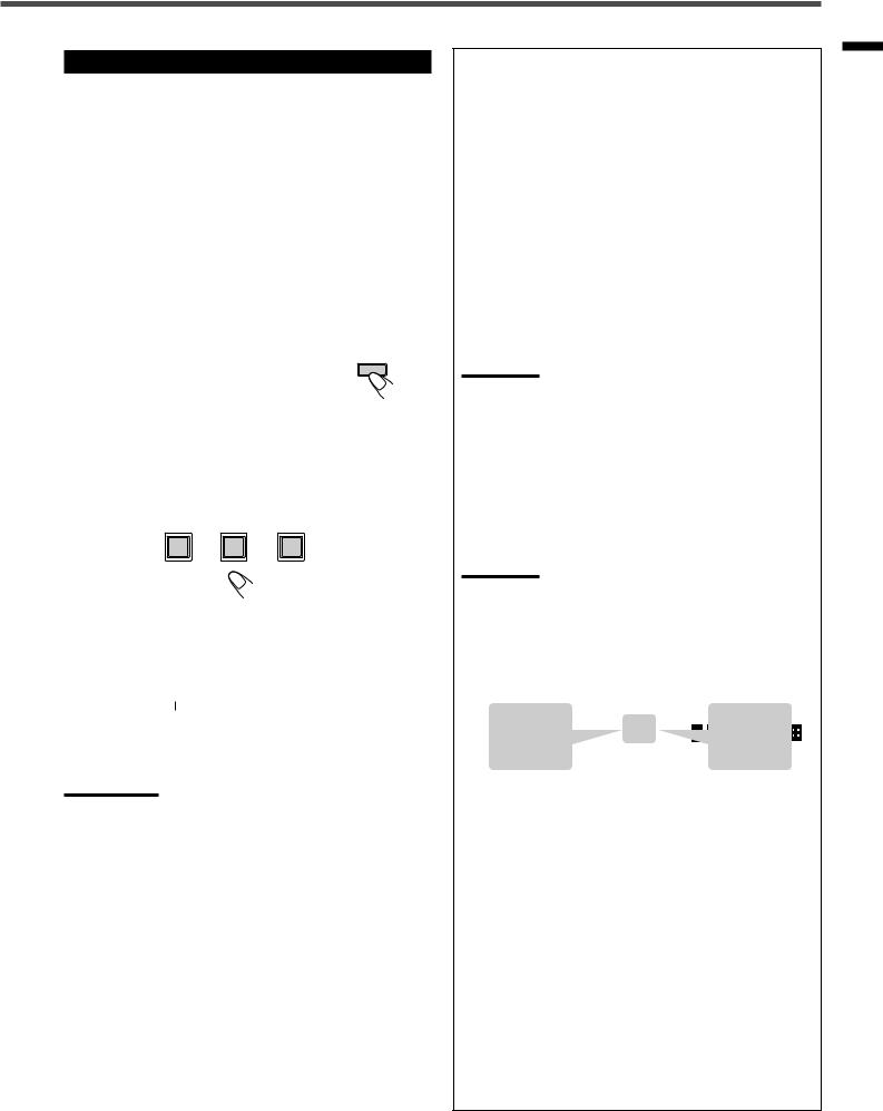
Activating TV Direct
TV Direct is enable you to use this unit as an AV selector while the unit is not turned on.
When TV Direct is activated, the pictures and sounds go from the video components such as DVD player to the TV through this unit. In this case, you can use the video components and the TV as if you connect them directly.
•This function takes effect only when the video components and TV are connected to this unit with SCART cables.
•This function takes effect to the following sources — DVD, STB, and VCR.
•This unit can be automatically turned on or off, and/or select the source automatically when you set the TV Direct mode to “AUTO 1” or “AUTO 2.” For details, see “Setting the TV Direct mode”
on page 19.
To activate (or deactivate) TV Direct, follow the procedure below.
1 Press TV DIRECT. |
TV DIRECT |
All the indications disappear, then the source indicator currently selected lights red.
2Turning on the video component and TV.
3Press one of the source selecting buttons — DVD,
STB, or VCR.
The indicator corresponding to the selected source lights red.
DVD |
STB |
VCR |
To cancel TV Direct and turn off the unit, press  (or AUDIO
  on the remote control).
The unit is turned off and the STANDBY lamp lights up.
To cancel TV Direct and turn on the unit, press TV DIRECT on the unit (or AUDIO on the remote control).
The unit is turned on and the source indicator currently selected lights green.
Notes:
•When TV Direct is activated, you cannot enjoy all the sound effects this unit produces, and use the speakers connected to this unit.
•You can use T-V LINK function between TV and VCR while the TV
Direct is activated.
Basic adjustment auto memory
This unit memorizes sound settings for each source ....
•when you turn on the power,
•when you change the source, and
•when you change the analogue/digital input mode (see page 14).
When you change the source, the memorized settings for the newly selected source are automatically recalled.
The following can be stored for each source:
•Analogue/digital input mode (see page 14)
•Input attenuator mode (see page 20)
•Balance (see page 20)
•Bass boost (see page 21)
•Tone adjustment (see page 21)
•Subwoofer output level (see page 22)
•Surround mode settings (see pages 33, 37) Theatre Surround settings (see pages 35, 38) DAP mode settings (see pages 36, 39)
Note:
If the source is FM or AM, you can assign a different setting for each band.
For recording
You can record sounds of any source playing through the unit to the VCR or the cassette deck.
While recording, you can listen to the selected sound source at whatever sound level you like without affecting the sound levels of the recording.
Note:
Sound adjustments (see page 20) and DSP modes (see page 32) cannot affect the recording.
Signal and speaker indicators on the display
Signal indicators |
|
|
|
|
|
|
|
|
Speaker indicators |
||||||||||
|
|
|
|
|
|
|
|
|
|
|
|
|
|
|
|
|
|
|
|
L |
C |
R |
|
|
|
|
|
|
|
|
|
|
L C |
R |
|||||
|
ANALOG |
L |
|
C |
|
R |
PRO LOGIC |
SLEEP |
|||||||||||
|
|
|
|
LPCM |
|
|
|
|
|
|
DSP |
|
|
|
|
|
|
|
|
|
|
LFE |
|
SUBWFR LFE |
SUBWFR |
|
|
||||||||||||
|
|
|
DOLBY D |
LS |
|
S |
|
RS |
DGTL AUTO |
|
|
||||||||
|
|
|
|
DTS |
|
|
|
|
|
|
INPUT ATT |
|
|
|
|
|
|
|
|
|
|
|
|
|
|
|
|
|
|
|
|
|
|
|
|
|
|
|
|
LS |
S |
RS |
|
|
|
|
|
|
|
|
|
|
|
|
|
|
|
|
|
|
|
|
|
|
|
|
|
|
LS |
|
RS |
|
|||||||
The following signal indicators light up —:
L: • When digital input is selected: Lights up when the left channel signal comes in.
•When analog input is selected: Always lights up. R: • When digital input is selected: Lights up when the
right channel signal comes in.
•When analog input is selected: Always lights up.
C : Lights up when the center channel signal comes in. LS : Lights up when the left rear channel signal comes in. RS : Lights up when the right rear channel signal comes in.
S : Lights up when the monaural rear channel signal comes in. LFE: Lights up when the LFE channel signal comes in.
The speaker indicators light up as follows:
•The subwoofer speaker indicator (SUBWFR) lights up when “SUBWFR” is set to “YES” (see page 15).
•The other speaker indicators light up only when the corresponding speaker is activated AND when the corresponding speaker is required for the DSP mode currently selected.
Operations Basic
11
Basic Operations
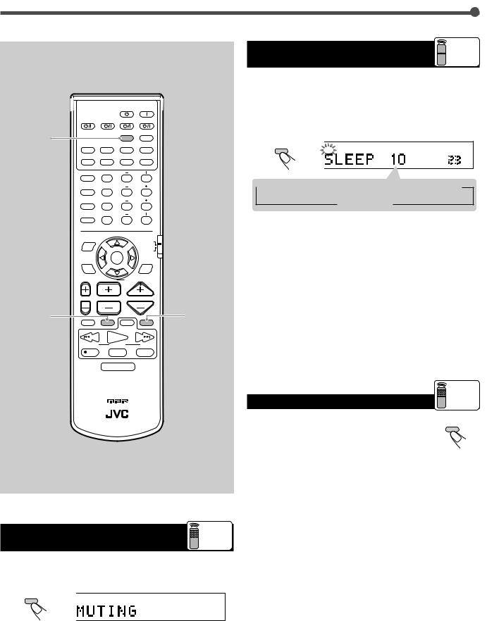
Turning Off the Power with the Timer

 Remote
ONLY
|
|
|
AUDIO |
DVD |
STB |
VCR |
TV |
|
|
SLEEP |
TV DIRECT |
SLEEP
You can fall asleep while listening to music — Sleep Timer.
Press SLEEP on the remote control repeatedly.
The SLEEP indicator lights up on the display, and the shut-off time changes in 10 minute intervals.
DVD |
STB |
VCR |
TV |
SLEEP |
|
|
|
|
|
|
L |
R |
SLEEP |
ANALOG/DIGITAL |
TAPE |
FM |
AM |
LPCM |
|
|
|
|
DGTL AUTO |
||||
INPUT |
|
|
|
|
|
|
|
|
|
|
|
|
VOL |
SOUND |
BASS+ |
CENTER |
|
|
1 |
2 |
3 |
TEST |
BASS– |
REAR-L |
|
|
4 |
5 |
6 |
BASS BOOST |
TREBLE+ |
REAR-R |
|
|
7 |
8 |
9 |
EFFECT |
TREBLE– |
SUBWOOFER |
|
|
10 |
0 |
+10 |
|
RETURN FM MODE |
100+ |
|
|
EON SELECT |
|
|
DISPLAY MODE |
|
RDS |
|
|
|
|
|
|
|
|
DVD |
DVD MENU |
EON |
|
MENU |
PTY( |
|
PTY9 |
|
ENTER |
|
||
DSP |
|
|
SURROUND |
MODE |
|
|
ON/OFF |
|
|
PTY SEARCH |
|
TV VOL |
CHANNEL |
VOLUME |
|
 10
10  20
20  30
30  40
40  50
50  60
60  70
70  80
80  90
90
0 (Canceled) 
When the shut-off time comes
The unit turns off automatically.
To check or change the time remaining until the shut-off time
Press SLEEP once.
The remaining time (in minutes) until the shut-off time appears.
• To change the shut-off time, press SLEEP repeatedly.
DIMMER |
|
|
MUTING |
To cancel the Sleep Timer |
|
|
Press SLEEP repeatedly until “SLEEP 0” appears on the display. |
||
TV/VIDEO |
DIMMER VCR |
MUTING |
|
|
|
CONTROL |
|
|
(The SLEEP indicator goes off.) |
|
PLAY |
|
|
|
/REW |
FF/ |
|
• Turning off the power also cancels the Sleep Timer. |
|
DOWN |
TUNING |
UP |
|
|
|
|
|||
REC |
STOP |
PAUSE |
|
|
RM-SRXE100R REMOTE CONTROL
HOME CINEMA CONTROL CENTER
Turning Off the Sounds |
Remote |
Temporarily |
ONLY |
Press MUTING on the remote control to mute the sound through all speakers connected.
Changing the Display Brightness |
Remote |
ONLY |
|
You can dim the display. |
DIMMER |
|
Press DIMMER on the remote control.
• Each time you press the button, the display dims and brightens alternately.
MUTING
TO
“MUTING” appears on the display and the volume turns off (the volume level indicator goes off).
To restore the sound, press MUTING again so that “MUTING OFF” appears on the display.
• Pressing MASTER VOLUME  /
/ (or VOLUME +/–) also restores the sound.
12
Loading...