


 Loading...
AUDIO/VIDEO CONTROL RECEIVER
RX-6010VBK / RX-6018VBK
POWER
SLEEP |
TV |
VCR |
AUDIO |
|
|
SURROUND |
TEST |
– SUBWOOFER + |
|
|
|
|
1 |
2 |
3 |
|
|
SURROUND |
EFFECT |
|
5 |
|
|
MODE |
– CENTER + |
|
|
||
|
4 |
5 |
6 |
5 |
|
|
5 |
|
|
AUDIO/VIDEO CONTROL RECEIVER |
|
SOUND |
– VCR CH + – REAR•L + |
|
|||
7/P 


 8
8 


 9
9
5MENU
TV/VIDEO |
CD-DISC |
– REAR•R + |
FM/AM TUNING |
FM/AM PRESET |
FM MODE |
|
|
|
10 |
+10 |
|
|
|
DVD |
|
|
ENTER |
STANDBY |
|
|
TV SOUND |
VCR ANALOG/DIGITAL |
|
MASTER VOLUME |
|||
|
|
|
|
POWER |
|
MEMORY |
|
|
|
|
|
|
|
CD |
TAPE/CDR |
|
FM/AM |
|
|
|
|
|
|
MUTING |
|
D I G I T A L |
|
++
TV VOL |
VOLUME |
|
|
|
|
|
|
|
– |
– |
8 |
SURROUND ON/OFF |
INPUT ANALOG |
INPUT DIGITAL |
|
ADJUST |
SETTING |
|
£ |
|
|
|
DVD |
VCR |
TV SOUND |
|
+ |
1 |
1 |
|
INPUT ATT |
|
|
|
|
TV CH |
|
|
|
|
|
|
|
|
– |
|
|
DSP MODE |
|
|
|
CONTROL |
|
|
|
|
SPEAKERS ON/OFF |
|
|
DOWN |
UP |
|
|
7 |
|
|
|
CD |
TAPE/CDR |
FM/AM |
|
|
RM-SRX6010J |
|
|
|
|
|
|
|
|
REMOTE CONTROL |
|
|
|
|
|
|
|
A/V CONTROL RECEIVER |
|
|
|
SOURCE NAME |
|
|
||
|
|
|
PHONES |
|
|
|
|
|
D I G I T A L
INSTRUCTIONS
For Customer Use:
Enter below the Model No. and Serial No. which are located either on the rear, bottom or side of the cabinet. Retain this information for future reference.
Model No.
Serial No.
LVT0578-001A
[J]
Warnings, Cautions and Others/
Mises en garde, précautions et indications diverses
|
|
CAUTION |
|
|
|
RISK OF ELECTRIC SHOCK |
|
|
|
DO NOT OPEN |
|
|
|
|
|
|
|
|
|
CAUTION: |
TO REDUCE THE RISK OF ELECTRIC SHOCK. |
||
|
DO NOT REMOVE COVER (OR BACK) |
||
|
NO USER SERVICEABLE PARTS INSIDE. |
||
REFER SERVICING TO QUALIFIED SERVICE PERSONNEL.
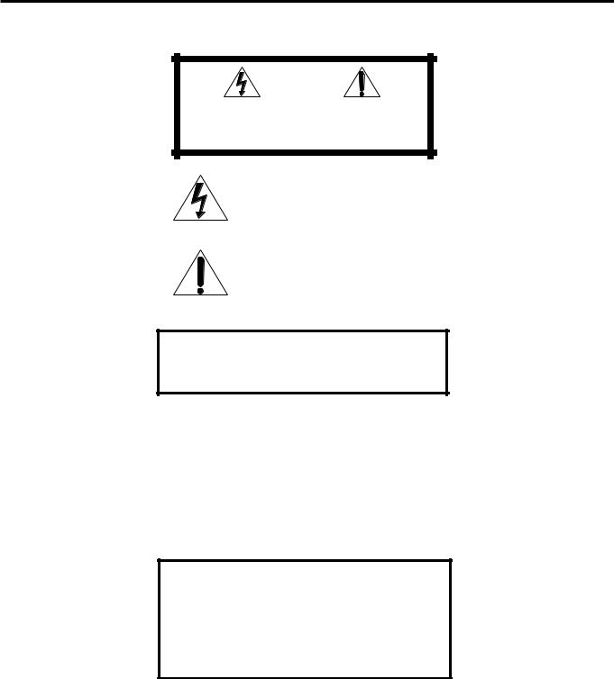
The lightning flash with arrowhead symbol, within an equilateral triangle is intended to alert the user to the presence of uninsulated "dangerous voltage" within the product's enclosure that may be of sufficient magnitude to constitute a risk of electric shock to persons.
The exclamation point within an equilateral triangle is intended to alert the user to the presence of important operating and maintenance (servicing) instructions in the literature accompanying the appliance.
WARNING: TO REDUCE THE RISK OF FIRE
OR ELECTRIC SHOCK, DO NOT EXPOSE
THIS APPLIANCE TO RAIN OR MOISTURE.
CAUTION
To reduce the risk of electrical shocks, fire, etc.:
1.Do not remove screws, covers or cabinet.
2.Do not expose this appliance to rain or moisture.
ATTENTION
Afin d’éviter tout risque d’électrocution, d’incendie, etc.:
1.Ne pas enlever les vis ni les panneaux et ne pas ouvrir le coffret de l’appareil.
2.Ne pas exposer l’appareil à la pluie ni à l’humidité.
Caution –– POWER switch!
Disconnect the mains plug to shut the power off completely. The POWER switch in any position does not disconnect the mains line. The power can be remote controlled.
Attention –– Commutateur POWER!
Déconnecter la fiche de secteur pour couper complètement le courant. Le commutateur POWER ne coupe jamais complètement la ligne de secteur, quelle que soit sa position. Le courant peut être télécommandé.
For Canada/pour Le Canada
THIS DIGITAL APPARATUS DOES NOT EXCEED THE CLASS
B LIMITS FOR RADIO NOISE EMISSIONS FROM DIGITAL
APPARATUS AS SET OUT IN THE INTERFERENCE-CAUSING
EQUIPMENT STANDARD ENTITLED “DIGITAL APPARATUS,”
ICES-003 OF THE DEPARTMENT OF COMMUNICATIONS.
CET APPAREIL NUMERIQUE RESPECTE LES LIMITES DE
BRUITS RADIOELECTRIQUES APPLICABLES AUX APPAREILS
NUMERIQUES DE CLASSE B PRESCRITES DANS LA NORME
SUR LE MATERIEL BROUILLEUR; “APPAREILS
NUMERIQUES”, NMB-003 EDICTEE PAR LE MINISTRE DES
COMMUNICATIONS.
For Canada/pour le Canada
CAUTION: TO PREVENT ELECTRIC SHOCK, MATCH WIDE
BLADE OF PLUG TO WIDE SLOT, FULLY INSERT
ATTENTION: POUR EVITER LES CHOCS ELECTRIQUES,
INTRODUIRE LA LAME LA PLUS LARGE DE LA FICHE DANS LA
BORNE CORRESPONDANTE DE LA PRISE ET POUSSER
JUSQUAU FOND
For U.S.A.
This equipment has been tested and found to comply with the limits for a Class B digital device, pursuant to part 15 of the FCC Rules. These limits are designed to provide reasonable protection against harmful interference in a residential installation.
This equipment generates, uses and can radiate radio frequency energy and, if not installed and used in accordance with the instructions, may cause harmful interference to radio communications. However, there is no guarantee that interference will not occur in a particular installation. If this equipment does cause harmful interference to radio or television reception, which can be determined by turning the equipment off and on, the user is encouraged to try to correct the interference by one or more of the following measures:
Reorient or relocate the receiving antenna.
Increase the separation between the equipment and receiver. Connect the equipment into an outlet on a circuit different from that to which the receiver is connected.
Consult the dealer or an experienced radio/TV technician for help.
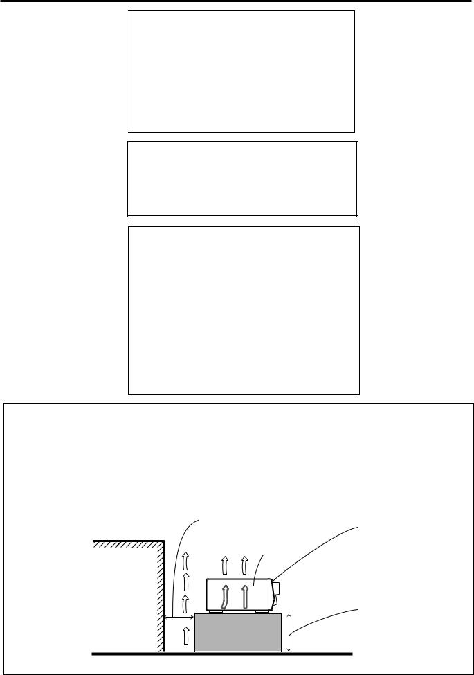
Caution: Proper Ventilation |
Attention: Ventilation Correcte |
||
To avoide risk of electric shock and fire and to protect from dam- |
Pour éviter les chocs électriques, l’incendie et tout autre dégât. |
||
age. |
|
Disposer l’appareil en tenant compte des impératifs suivants |
|
Locate the apparatus as follows: |
Avant: |
Rien ne doit gêner le dégagement |
|
Front: |
No obstructions open spacing. |
Flancs: |
Laisser 10 cm de dégagement latéral |
Sides: |
No obstructions in 10 cm from the sides. |
Dessus: |
Laisser 10 cm de dégagement supérieur |
Top: |
No obstructions in 10 cm from the top. |
Arrière: |
Laisser 15 cm de dégagement arrière |
Back: |
No obstructions in 15 cm from the back |
Dessous: |
Rien ne doit obstruer par dessous; poser l’appareil |
Bottom: |
No obstructions, place on the level surface. |
|
sur une surface plate. |
In addition, maintain the best possible air circulation as illustrated. |
Veiller également à ce que l’air circule le mieux possible comme |
||
|
Spacing 15 cm or more |
illustré. |
|
|
|
|
|
|
Dégagement de 15 cm ou plus |
|
|
|
|
|
Front |
|
|
RX-6010VBK/ |
Avant |
|
|
|
|
|
|
RX-6018VBK |
|
|
Wall or obstructions |
|
|
|
Mur, ou obstruction |
|
|
|
|
|
Stand height 15 cm or more |
|
|
|
Hauteur du socle: 15 cm ou plus |
Floor
Plancher

Table of Contents |
|
Parts Identification ...................................... |
2 |
Getting Started........................................... |
3 |
Before Installation ...................................................................... |
3 |
Checking the Supplied Accessories ........................................... |
3 |
Connecting the FM and AM Antennas ....................................... |
3 |
Connecting the Speakers ............................................................ |
4 |
Connecting Audio/Video Components ....................................... |
5 |
Connecting the Power Cord ....................................................... |
7 |
Putting Batteries in the Remote Control .................................... |
7 |
Basic Operations ......................................... |
8 |
Turning the Power On and Off (Standby) .................................. |
8 |
Selecting the Source to Play ....................................................... |
8 |
Adjusting the Volume ................................................................. |
9 |
Listening Only with Headphones ............................................... |
9 |
Muting the Sound ....................................................................... |
9 |
Adjusting the Subwoofer Output Level .................................... |
10 |
Attenuating the Input Signal .................................................... |
10 |
Adjusting the Tone ................................................................... |
10 |
Basic Settings........................................... |
11 |
Recording a Source .................................................................. |
11 |
Adjusting the Front Speaker Output Balance ........................... |
11 |
Setting the Subwoofer Information .......................................... |
11 |
Changing the Source Name ...................................................... |
11 |
Setting the Speakers for the DSP Modes ................................. |
12 |
Digital Input (DIGITAL IN) Terminal Setting ......................... |
14 |
Selecting the Analog or Digital Input Mode ............................ |
14 |
Storing the Basic Settings and Adjustments ............................. |
15 |
Using the Sleep Timer .............................................................. |
15 |
Receiving Radio Broadcasts ........................ |
16 |
Tuning in Stations Manually .................................................... |
16 |
Using Preset Tuning ................................................................. |
16 |
Selecting the FM Reception Mode ........................................... |
17 |
Using the DSP Modes ................................ |
18 |
What are the DSP Modes? ....................................................... |
18 |
Reproducing the Sound Field ................................................... |
19 |
Available DSP Modes According to the Speaker Arrangement .. |
20 |
Adjusting the Surround Modes ................................................ |
21 |
Adjusting the DAP Modes ....................................................... |
23 |
Activating the DSP Modes ....................................................... |
24 |
COMPU LINK Remote Control System ......... |
25 |
Operating JVC’s Audio/Video Components ... |
26 |
Operating Audio Components .................................................. |
26 |
Operating Video Components .................................................. |
27 |
Troubleshooting ......................................... |
28 |
Specifications............................................ |
29 |
1

 Parts Identification
Become familiar with the buttons and controls on the receiver before use.
Refer to the pages in parentheses for details.
1 |
2 |
3 |
4 |
5 |
6 |
7 8 |
9 |
p |
|
|
|
|
|
|
AUDIO/VIDEO CONTROL RECEIVER |
|
|
|
|
|
FM/AM TUNING |
FM/AM PRESET |
FM MODE |
|
|
|
|
|
|
STANDBY |
|
|
|
|
|
|
|
|
MASTER VOLUME |
|
|
|
MEMORY |
|
|
|
|
|
|
POWER |
|
|
|
|
|
|
|
|
|
|
|
|
|
|
|
|
|
|
|
|
D I G I T A L |
|
|
|
|
|
|
|
|
|
S U R R O U N D D I G I T A L |
|
|
|
|
|
|
|
|
|
SURROUND ON/OFF |
INPUT ANALOG |
INPUT DIGITAL |
|
ADJUST |
SETTING |
|
|
|
|
|
|
|
|
|||||
|
|
|
|
DVD |
VCR |
TV SOUND |
|
|
|
|
|
INPUT ATT |
|
|
|
|
|
|
|
|
DSP MODE |
|
|
|
|
CONTROL |
|
|
|
|
SPEAKERS ON/OFF |
|
|
DOWN |
UP |
|
|
||
|
|
|
|
CD |
TAPE/CDR |
FM/AM |
|
|
|
|
|
|
|
|
SOURCE NAME |
|
|
|
|
PHONES |
|
|
|
|
|
|
|
|
|
q w e r t y |
u i |
o |
1
2
3
4
5
6
7
8
9
p
POWER
SLEEP |
TV |
VCR |
AUDIO |
SURROUND |
TEST |
– SUBWOOFER + |
|
|
1 |
2 |
3 |
SURROUND |
|
5 |
|
MODE |
EFFECT |
– CENTER + |
|
|
4 |
5 |
6 |
|
5 |
|
5 |
SOUND |
– VCR CH + – REAR•L + |
||
|
7/P |
8 |
9 |
TV/VIDEO |
CD-DISC |
5 |
MENU |
– REAR•R + |
|||
|
|
10 |
+10 |
DVD |
|
|
ENTER |
TV SOUND |
VCR ANALOG/DIGITAL |
||
CD |
TAPE/CDR |
|
FM/AM |
MUTING
++
TV VOL |
VOLUME |
|
|
– |
|
– |
8 |
|
1 |
£ |
|
+ |
|
1 |
|
TV CH
–
7
RM-SRX6010J
REMOTE CONTROL
A/V CONTROL RECEIVER
Remote Control
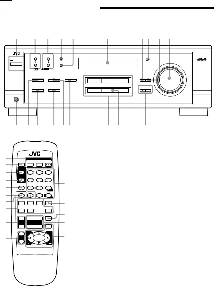
1POWER buttons (8, 27) TV, VCR, AUDIO
2 SLEEP button (15)
3 SURROUND button (21, 24, 26)
4 SURROUND MODE button
(22 – 24, 26)
5 SOUND button (10, 21 – 23, 26)
6 TV/VIDEO button (27)
q7 CD-DISC button (27)
8 Source selecting buttons (8, 9, 15) DVD, TV SOUND, VCR, CD,
TAPE/CDR, FM/AM
w9 TV VOL +/– buttons (27)
p TV CH +/– buttons (27)
eq • 10 keys for selecting preset channels
(17)
r• 10 keys for adjusting sound
(21 – 23, 26)
• 10 keys for operating audio/video
tcomponents (26, 27)
w ANALOG/DIGITAL button (15) e MUTING button (9)
r VOLUME +/– buttons (9)
tOperating buttons for audio/video components (26, 27)
Front Panel
1POWER button and STANDBY lamp
(8)
2 FM/AM TUNING 5/°buttons (16)
3 FM/AM PRESET 5/°buttons (16, 17)
4 FM MODE button (17)
5 MEMORY button (16)
6 Display (8)
7 ADJUST button (10, 11, 21 – 23)
8 Remote sensor (7)
9 SETTING button (11 – 14)
p MASTER VOLUME control (9) q PHONES jack (9)
w SURROUND ON/OFF button (21, 24) e DSP MODE button (22 – 24)
r SPEAKERS ON/OFF button (9) t INPUT ANALOG button (15)
INPUT ATT button (10)
y INPUT DIGITAL button (14)
uSource selecting buttons (8, 9, 14) DVD, VCR, TV SOUND, CD,
TAPE/CDR, FM/AM
i SOURCE NAME button (11)
*TAPE/CDR button also functions as the SOURCE NAME button
o CONTROL UP 5/DOWN °buttons
2

 Getting Started
This section explains how to connect audio/video components and speakers to the receiver, and how to connect the power supply.
Before Installation
General
•Be sure your hands are dry.
•Turn the power off to all components.
•Read the manuals supplied with the components you are going to connect.
Locations
•Install the receiver in a location that is level and protected from moisture.
•The temperature around the receiver must be between –5˚C and 35˚C (23˚F and 95˚F).
•Make sure there is good ventilation around the receiver. Poor ventilation could cause overheating and damage the receiver.
Handling the receiver
•Do not insert any metal object into the receiver.
•Do not disassemble the receiver or remove screws, covers, or cabinet.
•Do not expose the receiver to rain or moisture.
Checking the Supplied Accessories
Check to be sure you have all of the following items, which are supplied with the receiver.
The number in the parentheses indicates the quantity of the pieces supplied.
•Remote Control (1)
•Batteries (2)
•AM Loop Antenna (1)
•FM Antenna (1)
If anything is missing, contact your dealer immediately.
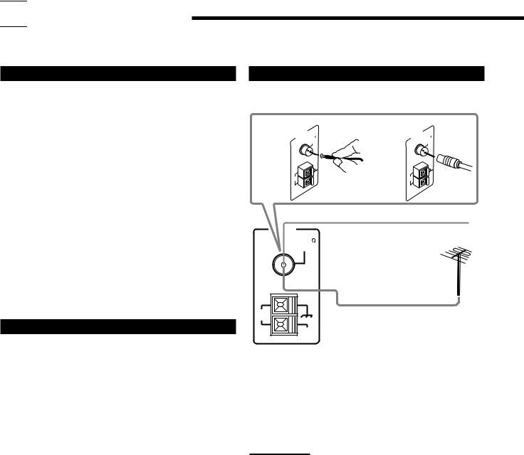
Connecting the FM and AM Antennas
FM Antenna Connections
A |
|
AN |
TENNA |
M |
75L |
|
B |
|
ANTENNA |
M 75L |
|
||||
|
|
|
F |
|
AXIA |
|
|
|
|
F |
|
AXIA |
|
|
|
|
|
|
CO |
|
|
|
|
|
|
CO |
|
|
|
||
|
A |
M |
|
|
|
A |
M |
|
A |
M |
|
A |
M |
||
|
OP |
|
|
|
EX |
T |
|
OP |
|
EX |
T |
||||
|
LO |
|
|
|
|
|
LO |
|
|
||||||
|
|
|
|
|
|
|
|
|
|
|
|
|
|
||
FM Antenna
Extend the supplied FM antenna horizontally.
AM |
Outdoor FM Antenna Cable |
LOOP |
|
AM
EXT
A.Using the Supplied FM Antenna
The FM antenna provided can be connected to the FM 75 Ω COAXIAL terminal as temporary measure.
B.Using the Standard Type Connector (Not Supplied)
A standard type connector should be connected to the FM 75 Ω COAXIAL terminal.
Note:
If reception is poor, connect an outdoor antenna.
Before attaching a 75 Ω coaxial cable (the kind with a round wire going to an outdoor antenna), disconnect the supplied FM antenna.
3
AM Antenna Connections Basic connecting procedure
|
1 |
2 |
3 |
ANTENNA |
Snap the tabs on the loop into the |
|
|
slots of the base to assemble the |
|
|
|
FM 75 |
|
|
|
AM loop. |
|
|
|
COAXIAL |
|
|
AM
LOOP
AM Loop Antenna
AM
EXT
1 |
2 |
3 |
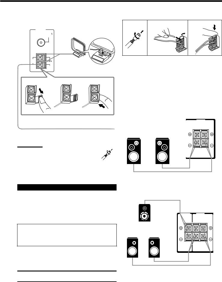
1Cut, twist and remove the insulation at the end of each speaker signal cable (not supplied).
2Open the terminal and then insert the speaker signal cable.
3Close the terminal.
Connecting the front speakers
Connect front speakers to the FRONT SPEAKERS terminals.
Outdoor single vinyl-covered wire (not supplied)
Turn the loop until you have the best reception. |
Left speaker |
Right speaker |
Notes:
• If the AM loop antenna wire is covered with vinyl, remove the vinyl by twisting it as shown in the diagram.
• Make sure the antenna conductors do not touch any other terminals, connecting cords and power cord. This could cause poor reception.
•If reception is poor, connect an outdoor single vinyl-covered wire to the AM EXT terminal. (Keep the AM loop antenna connected.)
FRONT |
|
SPEAKERS |
|
RIGHT |
LEFT |
Connecting the Speakers
You can connect the following speakers:
•One pair of front speakers to produce normal stereo sound.
•One pair of rear speakers to enjoy the surround effect.
•One center speaker to produce more effective surround effect (to emphasize human voices).
•One subwoofer to enhance the bass.
IMPORTANT:
After connecting the speakers listed above, set the speaker setting information properly to obtain the best possible DSP effect. For details, see page 12.
For each speaker (except for a subwoofer), connect the (+) and (–) terminals on the rear panel to the (+) and (–) terminals marked on the speakers. For connecting a subwoofer, see page 5.
CAUTION:
Use speakers with the SPEAKER IMPEDANCE indicated by the speaker terminals.
Connecting the rear and center speakers
Connect rear speakers to the REAR SPEAKERS terminals and a center speaker to the CENTER SPEAKER terminals.
|
CENTER |
REAR |
|
|
SPEAKER |
SPEAKERS |
|
Center speaker |
RIGHT |
LEFT |
|
|
|
||
Left rear |
Right rear |
|
|
speaker |
speaker |
|
|
4

Connecting the subwoofer speaker
You can enhance the bass by connecting a subwoofer. Connect the input jack of a powered subwoofer to the
SUBWOOFER OUT jack on the rear panel, using a cable with RCA pin plugs (not supplied).
|
SUBWOOFER |
Powered subwoofer |
OUT |
|
Connecting Audio/Video Components
You can connect the following audio/video components to this receiver. Refer also to the manuals supplied with your components.
Audio Components |
Video Components |
• CD player* |
• DVD player* |
|
|
• Cassette deck |
• TV* |
or CD recorder* |
• VCR |
|
|
*You can connect these components using the methods described in “Analog connections” (below) or in “Digital connections” (see page 7).
Analog connections
Audio component connections
Use the cables with RCA pin plugs (not supplied).
Connect the white plug to the audio left jack, and the red plug to the audio right jack.
CAUTION:
If you connect a sound-enhancing device such as a graphic equalizer between the source components and this receiver, the sound output through this receiver may be distorted.
CD player
CD player
|
CD |
|
OUT |
|
(REC) |
To audio output |
TAPE |
CDR |
|
|
IN |
|
(PLAY) |
|
OUT |
|
(REC) |
|
VCR |
|
IN |
|
(PLAY) |
|
TV SOUND |
RIGHT LEFT
AUDIO
Cassette deck or CD recorder |
|
|
|
Cassette deck |
|
To audio input |
PHONO |
To audio output |
|
CD |
|
CD
OUT (REC)
TAPE  CDR
CDR
IN (PLAY)
OUT (REC)
VCR
IN (PLAY)
TV SOUND
RIGHT LEFT
AUDIO
To audio input  To audio output CD recorder
Note:
You can connect either a cassette deck or a CD recorder to the TAPE/ CDR jacks. When connecting a CD recorder to the TAPE/CDR jacks, change the source name, which will be shown on the display when selected as the source, to “CDR.” See page 11 for details.
If your audio components have a COMPU LINK jack
See also page 25 for detailed information about the connection and the COMPU LINK remote control system.
5
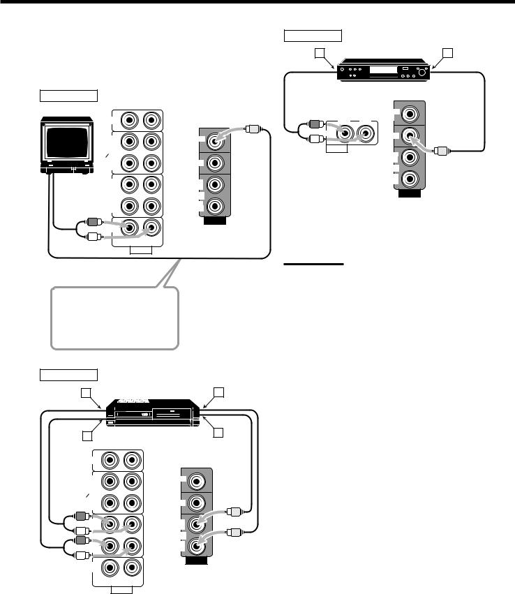
Video component connections
Use the cables with RCA pin plugs (not supplied).
Connect the white plug to the audio left jack, the red plug to the audio right jack, and the yellow plug to the video jack.
TV |
|
|
|
CD |
|
|
OUT |
MONITOR |
|
(REC) |
OUT |
|
TAPE |
|
|
CDR |
|
|
IN |
DVD |
|
(PLAY) |
|
TV |
OUT |
OUT |
|
||
|
(REC) |
(REC) |
|
VCR |
VCR |
To audio |
IN |
IN |
(PLAY) |
(PLAY) |
|
output |
|
VIDEO |
|
|
TV SOUND
RIGHT LEFT
AUDIO
To video input
Connect the TV to the MONITOR OUT jack to view the playback picture from the other connected video components.
VCR
A |
VCR |
C |
B |
|
D |
|
|
|
CD |
|
|
OUT |
MONITOR |
|
(REC) |
OUT |
|
TAPE |
|
|
|
|
|
CDR |
|
|
IN |
DVD |
|
(PLAY) |
|
|
OUT |
OUT |
|
(REC) |
(REC) |
|
VCR |
VCR |
|
IN |
IN |
|
(PLAY) |
(PLAY) |
|
VIDEO
TV SOUND
RIGHT LEFT
AUDIO
Å To left/right channel audio output ı To left/right channel audio input Ç To video output
Î To video input
DVD player
A |
DVD player |
B |
DVD |
|
|
MONITOR |
RIGHT |
LEFT |
OUT |
|
||
DVD |
|
DVD |
|
|
|
AUDIO |
|
|
|
|
OUT |
|
|
(REC) |
|
|
VCR |
|
|
IN |
|
|
(PLAY) |
VIDEO
Å To front left/right channel audio output (or to audio mixed output if necessary)
ı To video output
Note:
To enjoy the software encoded with Dolby Digital or DTS Digital Surround, you must connect the DVD player using the digital terminal on the rear of this receiver. (See “Digital connections” on page 7.)
6
Digital connections
This receiver is equipped with two DIGITAL IN terminals — one digital coaxial terminal and one digital optical terminal.
You can connect any component to one of the digital terminals using a digital coaxial cable (not supplied) or digital optical cable (not supplied).
IMPORTANT:
•When connecting the DVD player or digital TV broadcast tuner using the digital terminal, you also need to connect it to the video jack on the rear. Without connecting it to the video jack, you can view no playback picture.
•After connecting the components using the DIGITAL IN terminals, set the following correctly if necessary.
–Set the digital input (DIGITAL IN) terminal setting correctly. For details, see “Digital Input (DIGITAL IN) Terminal Setting” on page 14.
–Select the digital input mode correctly. For details, see “Selecting the Analog or Digital Input Mode” on page 14.
Digital TV
DVD player
DVD |
CD player |
CD recorder |
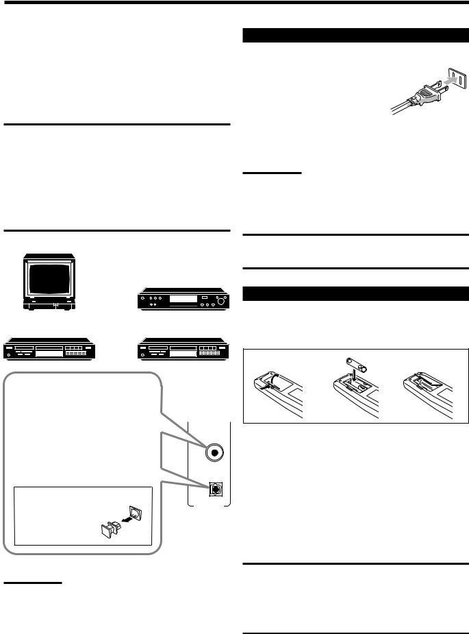
Connecting the Power Cord
Before plugging the receiver into an AC outlet, make sure that all connections have been made.
Plug the power cord into an AC outlet.
Keep the power cord away from the connecting cables and the antenna. The
power cord may cause noise or screen interference. We recommend that you use a coaxial cable to connect the antenna, since it is wellshielded against interference.
Note:
The preset settings such as preset channels and sound adjustment may be erased in a few days in the following cases:
–When you unplug the power cord.
–When a power failure occurs.
CAUTIONS:
•Do not touch the power cord with wet hands.
•Do not pull on the power cord to unplug the cord. When unplugging the cord, always grasp the plug so as not to damage the cord.
Putting Batteries in the Remote Control
Before using the remote control, put two supplied batteries first. When using the remote control, aim the remote control directly at the remote sensor on the receiver.
When the component has a digital coaxial output terminal, connect it to the DIGITAL 1 (DVD) terminal, using the digital coaxial cable (not supplied).
When the component has a digital optical output terminal, connect it to the DIGITAL 2 (CD) terminal, using the digital optical cable (not supplied).
Before connecting a digital optical cable, unplug the protective plug.
Notes:
DIGITAL 1 (DVD)
DIGITAL 2 ( CD )
DIGITAL IN
•When shipped from the factory, the DIGITAL IN terminals have been set for use with the following components.
–DIGITAL 1 (coaxial): For DVD player
–DIGITAL 2 (optical): For CD player
•When you want to operate the CD player or CD recorder using the COMPU LINK remote control system, connect the target component also as described in “Analog connections” (see page 5).
1 |
2 |
3 |
1.On the back of the remote control, remove the battery cover.
2.Insert batteries. Make sure to match the polarity:
(+) to (+) and (–) to (–).
3.Replace the cover.
If the range or effectiveness of the remote control decreases, replace the batteries. Use two R6P(SUM-3)/AA(15F) type dry-cell batteries.
CAUTION:
Follow these precautions to avoid leaking or cracking cells:
•Place batteries in the remote control so they match the polarity: (+) to (+) and (–) to (–).
•Use the correct type of batteries. Batteries that look similar may differ in voltage.
•Always replace both batteries at the same time.
•Do not expose batteries to heat or flame.
7

 Basic Operations
The following operations are commonly used when you play any sound source.
Turning the Power On and Off (Standby)
On the front panel:
To turn on the power, press POWER. |
STANDBY |
|
|
||
The STANDBY lamp goes off. The name of |
POWER |
|
the current source (or station frequency) |
||
|
||
appears on the display. |
|
Selected source name appears
DIGITAL AUTO |
SPK |
INPUT ATT |
SLEEP |
|
ANALOG |
L |
C |
R PROLOGIC DSP H.PHONE AUTOMUTING TUNED STEREO |
VOLUME |
LINEAR PCM |
S.WFR LFE |
|
||
DIGITAL |
LS |
S |
RS |
|
|
|
|
CH- |
|
|
|
|
|
|
Current source name appears
SPK
ANALOG |
L |
R |
VOLUME |
Current volume level is shown here
To turn off the power (into standby mode), press POWER again.
The STANDBY lamp lights up. A small amount of power is consumed in standby mode. To turn the power off completely, unplug the AC power cord.
From the remote control:
To turn on the power, press AUDIO in the POWER section.
The STANDBY lamp goes off. The name of the current source (or station frequency) appears on the display.
To turn off the power (into standby mode), press AUDIO in the POWER section again. The STANDBY lamp lights up.
 STANDBY
POWER
AUDIO
DVD |
Select the DVD player. |
TV SOUND |
Select the TV sound. |
VCR |
Select the video component connected to the |
|
VCR jacks. |
CD * |
Select the CD player. |
TAPE/CDR * |
Select the cassette deck (or the CD recorder). |
FM/AM * |
Select an FM or AM broadcast. |
|
• Each time you press the button, the band |
|
alternates between FM and AM. |
Notes:
•When connecting a CD recorder (to the TAPE/CDR jacks), change the source name that appears on the display. See page 11 for details.
•When you have connected some digital source components using the digital terminals (see page 7), you need to select the digital input mode.
•When you press one of the source selecting buttons on the remote control marked above with an asterisk (*), the receiver automatically turns on.
Signal and speaker indicators on the display
The signal indicators light up in the following cases:
•Only the indicators for the incoming signals light up.
•When analog input is selected, “L” and “R” always light up.
Selecting the Source to Play |
The speaker indicators light up only —: |
|
• When the corresponding speaker is activated. |
|
Press one of the source selecting buttons.
On the front panel:
DVD |
VCR |
TV SOUND |
CD |
TAPE/CDR |
FM/AM |
|
SOURCE NAME |
|
From the remote control:
AND
• When the corresponding speaker is required for the DSP mode selected currently.
Signal indicators light up in |
Speaker indicators light up |
red: |
in white: |
L |
C |
R |
L |
C |
R |
S.WFR LFE |
S.WFR LFE |
||||
LS |
S |
RS |
LS |
S |
RS |
DVD |
TV SOUND |
VCR |
CD |
TAPE/CDR |
FM/AM |
L: • When digital input is selected: Lights up when the left channel signal comes in.
• When analog input is selected: Always lights up.
R: • When digital input is selected: Lights up when the right channel signal comes in.
•When analog input is selected: Always lights up.
C:Lights up when the center channel signal comes in. LS: Lights up when the left rear channel signal comes in. RS: Lights up when the right rear channel signal comes in.
S: Lights up when the monaural rear channel signal comes in. LFE: Lights up when the LFE channel signal comes in.
Note:
When “SUBWOOFER” is set to “YES” (see page 11), S.WFR lights up.
8
Loading...