


AUDIO/VIDEO CONTROL RECEIVER
RECEPTOR DE CONTROL DE AUDIO/VÍDEO
RECEPTOR DE COMANDO AUDIO/VÍDEO
RX-5000VBK / RX-5001VGD
|
|
TV |
|
TA |
M |
|
A |
M AM |
|
T |
|
|
|
4 |
5 |
V |
|
|
|
|
|
7 |
|
|
V |
U |
|
|
|
|
|
V |
M T |
- |
|
|
U H |
|
|
P |
A |
|
|
|
|
|
+ |
M T |
|
V M |
|
V A
T T U U
2 5 3
– T +
5 |
6 |
5 |
– |
A • + |
|
8 5


 9
9
M U
–A • +
0 


 + 0
+ 0
TV V |
|
|
|
|
|
|
– |
+ |
|
|
|
|
MA T V M |
|
A |
V |
T |
V |
|
|
V |
|
|
|
|
|
– |
– |
+ |
|
|
|
|
|
|
TA |
|
|
|
|
|
|
|
|
|
A |
T |
A T |
|
+ |
|
|
|
|
|
V |
/I |
|
|
|
|
T |
– –
TA
£
M M
8
 4 1
4 1
4 1
7
V M T V V M M T
|
|
|
|
|
|
ONE OU H O ERA ION |
- |
X |
M T |
T |
AK |
TA M |
AM |
|
|
|
|
2 |
|
T ATT |
|
|
|
|
|
AM |
|
ON ÑO
INSTRUCTIONS
MANUAL DE INSTRUCCIONES INSTRUÇÕES
For Customer Use:
Enter below the Model No. and Serial No. which are located either on the rear, bottom or side of the cabinet. Retain this information for future reference.
Model No.
Serial No.
LVT0384-006A
[U, US]

Warnings, Cautions and Others / Avisos, precauciones y otras notas / Advertêcias, precauções e outras notas / 


CAUTION
To reduce the risk of electrical shocks, fire, etc.: 1. Do not remove screws, covers or cabinet.
2. Do not expose this appliance to rain or moisture.
PRECAUCIÓN
Para reducir riesgos de choques eléctricos, incendio, etc.:
1.No extraiga los tornillos, los cubiertas ni la caja.
2.No exponga este aparato a la lluvia o a la humedad.
ATENÇÃO
Para reduzir riscos de choques eléctricos, incêndio, etc.:
1. Não retire parafusos nem desmonte as tampas ou o gabinete. 2. Não exponha este aparelho à chuva nem à umidade.
Caution ––
 switch!
Disconnect the mains plug to shut the power off completely. The  switch in any position does not disconnect the mains line. The power can be remote controlled.
Precaución –– Interruptor 
 !
!
Desconectar el cable de alimentación para desactivar la alimentación totalmente. Cualquier que sea la posición de ajuste del interruptor
 , la alimentación no es cortada completamente. La alimentación puede ser controlada remotamente.
Precaução –– Interruptor !
!
Desconectar o cabo de alimentação para desligar a alimentação por completo. Qualquer que seja a posição de ajuste do interruptor  , a alimentação não é completamente cortada. A alimentação pode ser controlada remotamente.
G-1
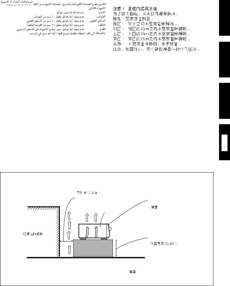
Caution: Proper Ventilation
To avoid risk of electric shock and fire and to protect from damage. Locate the apparatus as follows:
Front: |
No obstructions open spacing. |
Sides: |
No obstructions in 10 cm from the sides. |
Top: |
No obstructions in 10 cm from the top. |
Back: |
No obstructions in 15 cm from the back |
Bottom: |
No obstructions, place on the level surface. |
In addition, maintain the best possible air circulation as illustrated.
Precaución: Ventilación Adecuada
Para evitar el riesgo de choque eléctrico e incendio y para proteger el aparato contra daños.
Ubique el aparato de la siguiente manera:
Frente: |
Espacio abierto sin obstrucciones |
Lados: |
10 cm sin obstrucciones a los lados |
Parte superior: |
10 cm sin obstrucciones en la parte superior |
Parte trasera: |
15 cm sin obstrucciones en la parte trasera |
Fondo: |
Sin obstrucciones, colóquelo sobre una superficie |
|
nivelada |
Además, mantenga la mejor circulación de aire posible como se ilustra.
Precaução: ventilação apropriada
Para prevenir o risco de choque elétrico ou incêndio e para proteger o aparelho contra danos.
Localize-o da seguinte maneira:
Frente: |
Espaço aberto, sem obstruções |
Lados: |
Espaço de 10 cm sem obstruções nos lados |
Topo: |
Espaço de 10 cm sem obstruções acima |
Atrás: |
Espaço de 15 cm sem obstruções atrás |
Parte inferior: |
Sem obstruções. Coloque o aparelho em superfície |
nivelada.
Mantenha, além disso, a maior circulação de ar possível, como indica a ilustração.
Spacing 15 cm or more
Espacio de 15 cm o más
Espaço de 15 cm ou mais
RX-5000VBK/
RX-5001VGD
Wall or obstructions
Pared u obstrucciones
Parede ou obstáculo
Front
Frente
Frente
Stand height 15 cm or more Allura del soporte 15 cm o más
Base com altura de 15 cm ou mais
Floor
Piso
Piso
English
Español
Português
G-2

English
Table of Contents |
|
Parts Identification ...................................... |
2 |
Getting Started........................................... |
3 |
Before Installation ...................................................................... |
3 |
Checking the Supplied Accessories ........................................... |
3 |
Connecting the FM and AM Antennas ....................................... |
3 |
Connecting the Speakers ............................................................ |
4 |
Connecting Audio/Video Components ....................................... |
5 |
Connecting the Power Cord ....................................................... |
7 |
Putting Batteries in the Remote Control .................................... |
7 |
Basic Operations ......................................... |
8 |
Turning the Power On and Off (Standby) .................................. |
8 |
Selecting the Source to Play ....................................................... |
8 |
Adjusting the Volume ................................................................. |
9 |
Selecting the Front Speakers ...................................................... |
9 |
Muting the Sound ....................................................................... |
9 |
Recording a Source .................................................................... |
9 |
Attenuating the Input Signal .................................................... |
10 |
Adjusting the Front Speaker Output Balance ........................... |
10 |
Reinforcing the Bass ................................................................ |
10 |
Adjusting the Tone ................................................................... |
10 |
Basic Settings........................................... |
11 |
Changing the Source Name ...................................................... |
11 |
Setting Center and Rear Speakers for the DSP Modes ............ |
11 |
Storing the Basic Settings and Adjustments — One Touch |
|
Operation ........................................................................... |
12 |
Using the Sleep Timer .............................................................. |
12 |
Receiving Radio Broadcasts ........................ |
13 |
Setting the AM Tuner Internal Spacing .................................... |
13 |
Tuning in Stations Manually .................................................... |
13 |
Using Preset Tuning ................................................................. |
13 |
Selecting the FM Reception Mode ........................................... |
14 |
Using the DSP Modes ................................ |
15 |
Available DSP Modes According to the Speaker Arrangement .. |
16 |
Adjusting the 3D-PHONIC Modes .......................................... |
17 |
Adjusting the DAP Modes ....................................................... |
17 |
Adjusting the Surround Modes — Dolby Surround and JVC |
|
Theater Surround ............................................................... |
18 |
Activating the DSP Modes ....................................................... |
19 |
Using the DVD MULTI Playback Mode .......... |
20 |
Activating the DVD MULTI Playback Mode .......................... |
20 |
COMPU LINK Remote Control System ......... |
21 |
Operating JVC’s Audio/Video Components ... |
22 |
Troubleshooting ......................................... |
24 |
Specifications............................................ |
25 |
1
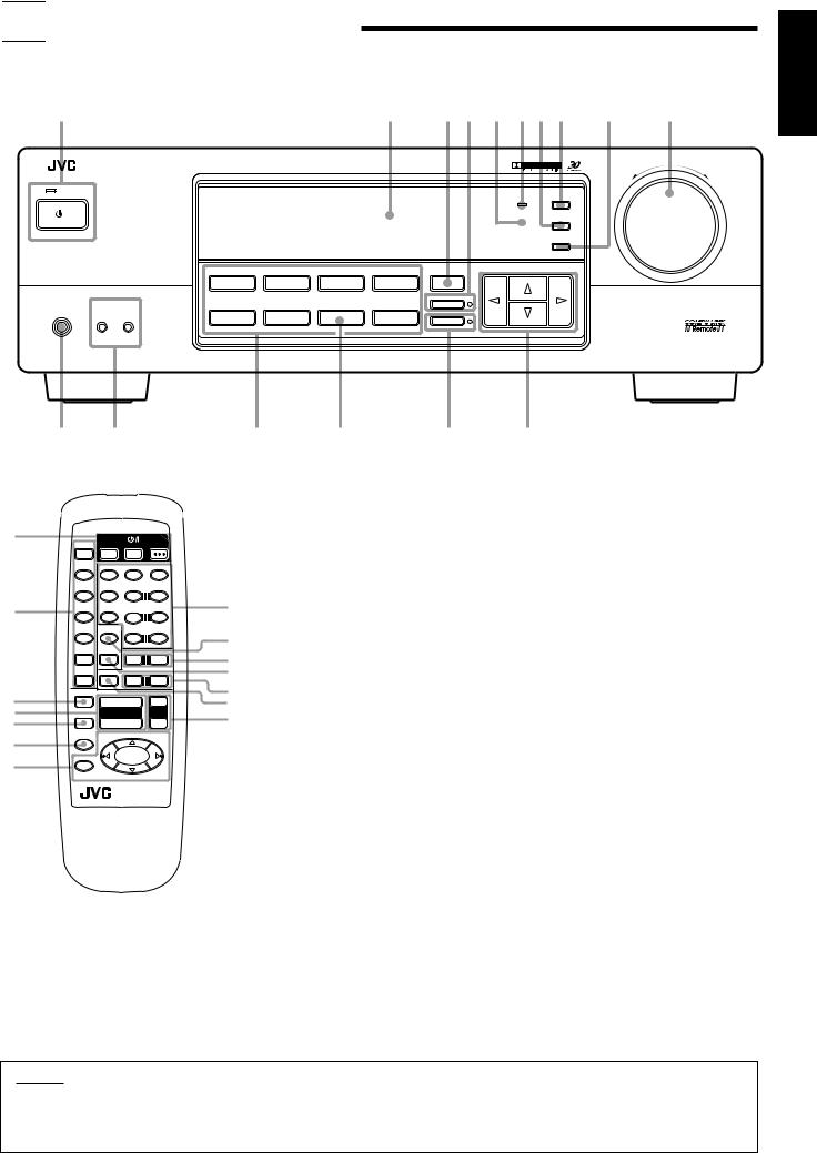

 Parts Identification
Become familiar with the buttons and controls on the receiver before use.
Refer to the pages in parentheses for details.
1 |
|
|
|
|
2 |
3 4 5 6 7 8 |
9 |
p |
||
|
|
|
|
|
|
|
|
|
|
MASTER VOLUME |
|
|
AUDIO/VIDEO CONTROL RECEIVER |
|
|
|
|
|
|
|
|
|
|
|
|
|
|
|
|
|
– |
+ |
S ANDB |
|
|
|
|
|
|
|
|
|
|
|
|
|
|
|
|
|
BASS BOOST |
ADJUST |
|
|
/I |
|
|
|
|
|
|
|
SETTING |
|
|
|
|
|
|
|
|
|
|
|
|
|
S ANDB ON |
|
|
|
|
|
|
|
|
|
|
|
|
|
|
|
|
|
|
MEMORY |
|
|
|
|
DVD MULTI |
DVD |
VCR |
FM |
SURROUND |
MULTI CURSOR |
|
|
|
|
|
|
|
|
|
ONE TOUCH OPERATION |
|
|
|
|
|
SPEAKERS |
CD |
PHONO |
TAPE/MD |
AM |
|
|
|
|
|
PHONES |
1 |
2 |
|
|
|
INPUT ATT. |
|
|
|
|
SOURCE NAME
_ON ÑOFF
English
y t |
r |
e |
w |
q |
1
2
3
4
5
6
7
CD |
|
V |
VCR |
AUDIO |
|
APE/MD |
DELAY |
ES |
|
|
|
|
1 |
2 5 |
3 |
|
|
FM/AM |
EFFEC |
CEN ER |
|
||
|
4 |
5 |
5 |
6 |
5 |
VCR |
|
|
REAR L |
|
|
|
7/P |
8 5 |
9 |
|
|
DVD |
|
T |
|
M |
|
|
REAR R |
|
|||
|
|
|
10 |
+10 |
|
DVD MUL I |
CD DISC |
|
|
T |
|
|
V VOL |
|
|||
|
|
|
– |
+ |
|
PHONO |
TV/VIDEO |
|
V CH |
|
|
|
|
|
– |
+ |
|
T |
|
|
|
|
|
AT |
|
|
|
|
|
|
|
+ |
|
+ |
|
MU NG |
|
VOLUME |
VCR CH |
||
|
|
– |
|
– |
|
SLEEP |
|
|
£ |
|
|
8 |
|
|
|
|
|
|
4 |
|
4 |
||
|
1 |
|
7 |
1 |
|
|
|
|
|
|
|
RM SR558XU REMO E CON ROL
Front Panel
1 STANDBY/ON  button and STANDBY lamp (8)
2 Display (8)
3 SURROUND button (16)
4 ONE TOUCH OPERATION button and lamp
8(12)
5 Remote sensor (7)
96 BASS BOOST lamp (10)
p7 SETTING button (11)*
q 8 ADJUST button (10)*
w9 MEMORY button (13)
ep MASTER VOLUME control (9)
rq Cursor control buttons
w INPUT ATT. button and lamp (10) e SOURCE NAME button (11)
r Source selecting buttons (8)
DVD MULTI, DVD, VCR, FM*, AM*, TAPE/MD, PHONO, CD
t SPEAKERS 1/2 buttons (9) y PHONES jack (9)
Remote Control
1  buttons (8, 23) TV, VCR, AUDIO
2Source selecting buttons (8)
CD, TAPE/MD, FM/AM, VCR, DVD,
DVD MULTI, PHONO
3 ONE TOUCH OPERATION button (12)
4 VOLUME +/– buttons (9)
5 MUTING button (9)
6 SLEEP button (12)
7 • Operating buttons for audio/video components
(22)
8• 10 keys for selecting preset channel (14, 22)
•10 keys for adjusting sound (12, 17, 22)
•10 keys for operating audio/video components
(22)
9 SOUND CONTROL button (12, 17, 22) p TV VOL. –/+ buttons (23)
q CD-DISC button (22) w TV CH –/+ buttons (23) e TV/VIDEO button (23)
r VCR CH +/– buttons (23)
IMPORTANT:
To use the Cursor control buttons (q) on the front panel:
What these buttons actually do depends on which function you are trying to adjust. Before using these buttons, select the function by pressing one of the buttons marked with *.
2
English

 Getting Started
This section explains how to connect audio/video components and speakers to the receiver, and how to connect the power supply.
Before Installation
General
•Be sure your hands are dry.
•Turn the power off to all components.
•Read the manuals supplied with the components you are going to connect.
Locations
•Install the receiver in a location that is level and protected from moisture.
•The temperature around the receiver must be between –5°C and 35°C (23°F and 95°F).
•Make sure there is good ventilation around the receiver. Poor ventilation could cause overheating and damage the receiver.
Handling the receiver
•Do not insert any metal object into the receiver.
•Do not disassemble the receiver or remove screws, covers, or cabinet.
•Do not expose the receiver to rain or moisture.
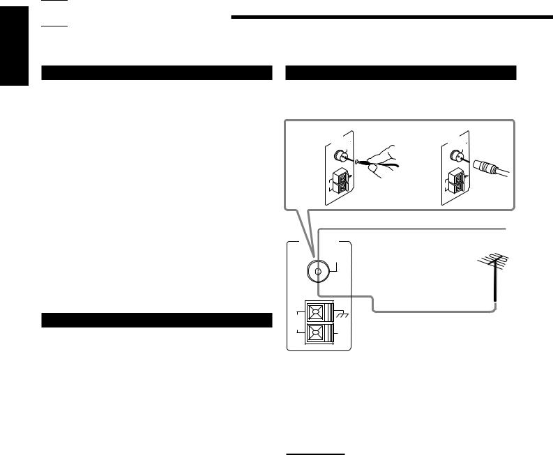
Connecting the FM and AM Antennas
FM Antenna Connections
A |
ANTENNA |
FM |
75 |
B |
ANTENNA |
FM |
75 |
|
|
COAXIAL |
|
|
COAXIAL |
||
|
AM |
|
AM |
|
AM |
|
AM |
|
|
EXT |
|
|
EXT |
||
|
LOOP |
|
|
LOOP |
|
||
|
|
|
|
|
|
||
FM Antenna
Extend the supplied FM antenna horizontally.
ANTENNA
FM 75
COAXIAL
Checking the Supplied Accessories
Check to be sure you have all of the following items, which are supplied with the receiver.
The number in the parentheses indicates quantity of the pieces supplied.
•Remote Control (1)
•Batteries (2)
•AM Loop Antenna (1)
•FM Antenna (1)
If anything is missing, contact your dealer immediately.
AM |
Outside FM Antenna Cable |
LOOP
AM
EXT
A. Using the Supplied FM Antenna
The FM antenna provided can be connected to the FM 75Ω COAXIAL terminal as temporary measure.
B. Using the Standard Type Connector (Not Supplied)
A standard type connector should be connected to the FM 75Ω COAXIAL terminal.
Note:
If reception is poor, connect the outside antenna.
Before attaching a 75Ω coaxial cable (the kind with a round wire going to an outside antenna), disconnect the supplied FM antenna.
3

AM Antenna Connections Basic connecting procedure
ANTENNA |
Snap the tabs on the loop into the |
1 |
2 |
3 |
|
|
|
||
slots of the base to assemble the |
|
|
|
|
FM 75 |
|
|
|
|
AM loop. |
|
|
|
|
COAXIAL |
|
|
|
English
AM
LOOP
AM
EXT AM Loop Antenna
1 |
2 |
3 |
Outdoor single vinyl-covered wire
Turn the loop until you have the best reception.
Notes:
•Make sure the antenna conductors do not touch any other terminals, connecting cords and power cord. This could cause poor reception.
•If reception is poor, connect an outdoor single vinyl-covered wire to the AM EXT terminal. (Keep the AM loop antenna connected.)
Connecting the Speakers
You can connect the following speakers:
•Two pairs of front speakers to produce normal stereo sound.
•One pair of rear speakers to enjoy the surround effect.
•One center speaker to produce more effective surround effect (to emphasize human voices).
•One subwoofer to enhance the bass.
IMPORTANT:
After connecting the speakers listed above, set the speaker setting information properly to obtain the best possible DSP (Digital Signal
Processor ) effect. For details, see page 11.
For each speaker (except for a subwoofer), connect the (–) and (+) terminals on the rear panel to the (–) and (+) terminals marked on the speakers. For connecting a subwoofer, see page 5.
CAUTION:
Use speakers with the SPEAKER IMPEDANCE indicated by the speaker terminals.
1Cut, twist and remove the insulation at the end of each speaker signal cable.
2Open the terminal and then insert the speaker signal cable.
3Close the terminal.
Connecting the front speakers
You can connect two pairs of front speakers (one pair to the FRONT SPEAKERS 1 terminals, and another pair to the FRONT SPEAKERS 2 terminals).
Right speaker |
|
FRONT SPEAKERS 1 |
|
Left speaker |
|
|
FRONT SPEAKERS
RIGHT LEFT
1 |
1 |
2 |
2 |
Right speaker |
|
FRONT SPEAKERS 2 |
|
Left speaker |
|
|
Connecting the rear and center speakers
Connect rear speakers to the REAR SPEAKERS terminals and a center speaker to the CENTER SPEAKER terminals.
Center speaker |
CENTER |
RIGHT |
LEFT |
|
SPEAKER |
|
|
||
Left rear |
Right rear |
|
|
REAR |
speaker |
speaker |
|
|
|
|
|
SPEAKERS |
||
4
English
Connecting the subwoofer speaker
You can enhance the bass by connecting a subwoofer. Connect the input jack of a powered subwoofer to the
SUBWOOFER OUT jack on the rear panel, using a cable with RCA pin plugs.
SUBWOOFER
OUT
Powered subwoofer
Connecting Audio/Video Components
You can connect the following audio/video components to this receiver using cables with RCA pin plugs (not supplied). Refer also to the manuals supplied with your components.
Use the cables with RCA pin plugs (not supplied).
Connect the white plug to the audio left jack, and the red plug to the audio right jack.
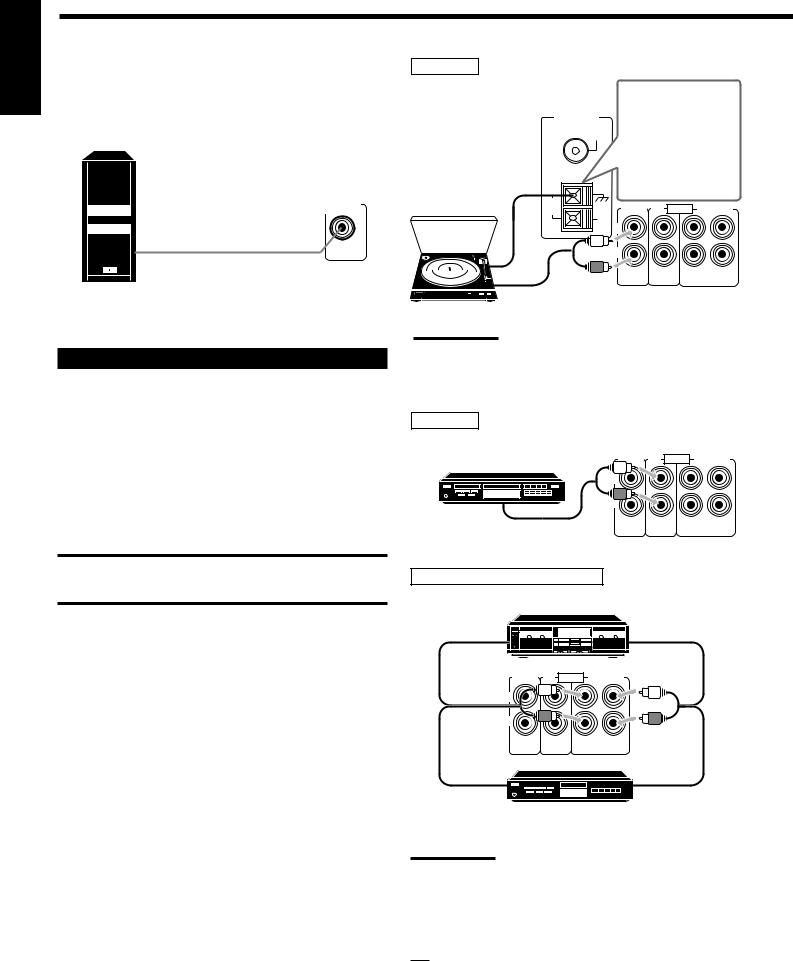
Audio component connections
CAUTION:
If you connect a sound-enhancing device such as a graphic equalizer between the source components and this receiver, the sound output through this receiver may be distorted.
Turntable
Turntable
ANTENNA
FM 75
COAXIAL
AM
LOOP
AM
EXT
If an earth cable is provided for your turntable, connect the cable to the ground terminal (H) of the
ANTENNA terminals on the rear panel.
PHONO CD AUDIO TAPE/MD
L
R
OUT |
IN |
(REC) |
(PLAY) |
To audio output
Note:
Any turntables incorporating a small-output cartridge such as an MC (moving-coil type) must be connected to this receiver through a commercial head amplifier or step-up transformer. Direct connection may result in insufficient volume.
CD player
CD player |
PHONO CD AUDIO |
TAPE/MD |
|
|
|
|
L |
|
|
R |
|
To audio output |
OUT |
IN |
(REC) |
(PLAY) |
|
Cassette deck or MD recorder |
|
|
Cassette deck |
|
|
To audio input |
To audio output |
|
PHONO CD AUDIO |
TAPE/MD |
|
L |
|
|
R |
|
|
OUT |
IN |
|
(REC) |
(PLAY) |
|
To audio input |
To audio output |
|
MD recorder |
|
|
Note:
You can connect either a cassette deck or an MD recorder to the TAPE/MD jacks. When connecting an MD recorder to the TAPE/MD jacks, change the source name, which will be shown on the display when selected as the source, to “M D.” See page 11 for details.
If your audio components have a COMPU LINK-3 terminal
See also page 21 for detailed information about the connection and the COMPU LINK-3 remote control system.
5
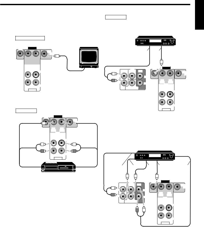
Video component connections
Use the cables with RCA pin plugs (not supplied).
Connect the white plug to the audio left jack, the red plug to the audio right jack and the yellow plug to the video jack.
TV (as the monitor)
TV (or Monitor)
DVD |
VIDEO |
|
MONITOR
OUT
|
OUT |
|
|
|
IN |
|
|
|
|
|
|
|
(REC) |
|
|
|
(PLAY) |
|
|
|
|
|
|
|
|
|
|
|
|
|
|
|
|
|
|
|
|
|
|
|
|
|
|
|
|||
|
OUT |
VCR |
|
|
|
|
|
||||
|
IN |
|
|
|
|
|
|||||
|
|
|
|
|
|
||||||
|
|
|
|
|
|
|
|
|
|||
|
|
|
|
|
|
|
|
|
|||
(REC) |
|
|
|
(PLAY) |
|
|
|
|
|
||
LEFT |
To video input |
|
|
RIGHT |
|
AUDIO
VCR
DVD |
VIDEO |
|
MONITOR


 OUT
OUT
OUT |
IN |
(REC) |
(PLAY) |
|
VCR |
OUT |
IN |
(REC) |
(PLAY) |
|
LEFT |
|
|
RIGHT |
|
AUDIO |
|
|
VHS |
|
To audio/video |
|
To audio/video |
input |
VCR |
output |
DVD player
• When you connect the DVD player with stereo output jacks:
DVD player
DVD |
•õ
DVD |
DVD |
VIDEO |
|
|
|
||
FRONT CENTER |
REAR |
|
MONITOR |
|
|
|
|
L |
|
|
OUT |
LEFT |
|
|
|
|
|
|
|
R |
|
OUT |
IN |
RIGHT |
(REC) |
(PLAY) |
|
|
|
VCR |
|
|
|
|
|
SUBWOOFER |
|
OUT |
IN |
|
|
(REC) |
(PLAY) |
LEFT
RIGHT
AUDIO
•To front left/right channel audio output (or to audio mixed output if necessary)
õ To video output
• When you connect the DVD player with its analog discrete output (5.1 CH reproduction) jacks:
DVD player
DVD |
• |
õ |
‚ |
ë |
ä |
|
DVD |
DVD |
VIDEO |
|
|
|
|
||
FRONT |
CENTER REAR |
|
|
MONITOR |
L |
|
|
|
OUT |
|
LEFT |
|
|
|
|
|
|
|
|
|
|
|
OUT |
IN |
R |
|
|
(REC) |
(PLAY) |
|
IGHT |
|
VCR |
|
|
|
|
||
|
|
|
|
|
|
SUBWOOFER |
|
OUT |
IN |
|
|
|
(REC) |
(PLAY) |
LEFT
RIGHT
AUDIO
• To front left/right channel audio output õ To center channel audio output
‚ To subwoofer audio output ë To video output
ä To rear left/right channel audio output
English
6
 Loading...