


LCD Flat Television Users Guide
For Models:
LT-32X585
LT-26X585
LT-32X575
LT-26X575
Illustration of LT-32X575 and RM-C1257G
Important Note:
In the spaces below, enter the model and serial number of your television (located at the rear of the television cabinet). Staple your sales receipt or invoice to the inside cover of this guide. Keep this user’s guide in a convenient place for future reference. Keep the carton and original packaging for future use.
Model Number:
Serial Number:
LCT1691-001A-A 0604TNH-II-IM
Important Safety Precautions
CAUTION
RISK OF ELECTRIC SHOCK
DO NOT OPEN
CAUTION: To reduce the risk of electric shock. Do not remove cover (or back). No user serviceable parts inside. Refer servicing to qualified service personnel.
The lightning flash with arrowhead symbol, within an equilateral triangle is intended to alert the user to the presence of uninsulated “dangerous voltage” within the product’s enclosure that may be of sufficient magnitude to constitute a risk of electric shock to persons.
The exclamation point within an equilateral triangle is intended to alert the user to the presence of important operating and maintenance (servicing) instructions in the literature accompanying the appliance.
WARNING: TO PREVENT FIRE OR SHOCK HAZARDS, DO NOT EXPOSE THIS TV SET TO RAIN OR MOISTURE.
CAUTION: TO INSURE PERSONAL SAFETY, OBSERVE THE FOLLOWING RULES REGARDING THE USE OF THIS UNIT.
1. Operate only from the power source specified on the unit.
2.Avoid damaging the AC plug and power cord.
3.Avoid Improper installation and never position the unit where good ventilation is unattainable.
4.Do not allow objects or liquid into the cabinet openings.
5.In the event of trouble, unplug the unit and call a service technician. Do not attempt to repair it yourself or remove the rear cover.
Changes or modifications not approved by JVC could void the warranty.
*When you don’t use this TV set for a long period of time, be sure to disconnect both the power plug from the AC outlet and antenna for your safety.
*To prevent electric shock do not use this polarized plug with an extension cord, receptacle or other outlet unless the blades can be fully inserted to prevent blade exposure.
IMPORTANT RECYCLING INFORMATION
This product has a fluorescent lamp that contains a small amount of mercury. It also contains lead in some components. Disposal of the materials may be regulated in your community due to environmental considerations. For disposal or recycling information, please contact your local authorities, or the Electronic Industries Alliance:
http://www.eiae.org
2

•As an “ENERGY STAR®” partner, JVC has determined
that this product or product model meets the “ENERGY STAR®” guidelines for energy efficiency.
IMPORTANT SAFETY INSTRUCTIONS
1)Read these instructions.
2)Keep these instructions.
3)Heed all warnings.
4)Follow all instructions.
5)Do not use this apparatus near water.
6)Clean only with dry cloth.
7)Do not block any ventilation openings. Install in accordance with the manufacturer's instructions.
8)Do not install near any heat sources such as radiators, heat registers, stoves, or other apparatus (including amplifiers) that produce heat.
9)Do not defeat the safety purpose of the polarized or grounding-type plug. A polarized plug has two blades with one wider than the other. A grounding type plug has two blades and a third grounding prong. The wide blade or the third prong are provided for your safety. If the provided plug does not fit into your outlet, consult an electrician for replacement of the obsolete outlet.
10)Protect the power cord from being walked on or pinched particularly at plugs, convenience receptacles, and the point where they exit from the apparatus.
11)Only use attachments/accessories specified by the manufacturer.
12)Use only with a cart, stand, tripod, bracket, or table specified by the manufacturer, or
sold with the apparatus. When a cart is used, use caution when moving the cart/apparatus combination to avoid injury from tip-over.
3

13)Unplug this apparatus during lightning storms or when unused for long periods of time.
14)Refer all servicing to qualified service personnel. Servicing is required when the apparatus has been damaged in any way, such as power-supply cord or plug is damaged, liquid has been spilled or objects have fallen into the apparatus, the apparatus has been exposed to rain or moisture, does not operate normally, or has been dropped.
15)Apparatus shall not be exposed to dripping or splashing and no objects filled with liquids, such as vases, shall be placed on the apparatus.
16)Avoid improper installation and never position the unit where good ventilation is impossible. When installing this TV, distance recommendations must be maintained between the set and the wall, as well as inside a tightly enclosed area or piece of furniture. Keep to the minimum distance guidelines shown for safe operation.
200 mm |
200 mm |
|
|
150 mm |
150 mm |
50 mm
17)Cautions for installation
—Do not tilt the TV towards the left or right, or towards the back.
—Install the TV in a corner on the floor so as to keep cords out of the way.
—The TV will generate a slight amount of heat during operation. Ensure that sufficient space is available around the TV to allow satisfactory cooling.
4

Warnings
Avoiding Ghost Images
Displaying fixed images for extended periods of time can leave a subtle but temporary ghost image on your screen. To avoid this, mix your viewing pattern.
Examples include, but are not limited to the following:
• |
Stock-market report bars |
For example... |
|
|
TV on |
TV off |
|||
• |
Shopping channel logos and pricing |
|||
|
|
|||
|
displays |
|
|
|
• |
Video game patterns or scoreboards |
|
|
|
• |
Bright station logos |
|
|
|
• |
Internet web sites or other computer-style |
|
|
|
|
images. |
|
|
|
• |
DVD discs, video tapes, laser discs |
|
|
|
• |
Broadcast, cable, satellite channels or |
XYZ |
XYZ |
|
|
digital television tuners/converters. |
|||
|
|
|
Caring for the Cabinet
Normally, light dusting with a soft, non-scratching duster will keep your TV clean.
If you wish to wipe down the television, first unplug it. Then wipe gently with a soft cloth, slightly moistened with water. You can add a few drops of mild liquid detergent to the water to help remove spots of oily dirt.
•DO NOT allow liquid to enter the TV through the ventilation slots.
•DO NOT use strong or abrasive cleaners on the TV.
•DO NOT spray liquids or cleaners directly on the TV’s surface.
•DO NOT rub or scrub the TV harshly. Wipe the set gently with a soft cloth.
Caring for the Screen
The screen is treated with an electrostatic-proof coating. When it gets dirty, wipe it gently with a soft cloth. If the screen is very dirty, wipe it down with a cloth dipped in a diluted kitchen cleaner and thoroughly wrung-out. Then wipe immediately after with a clean, dry cloth.
Do not apply alcohol, organic solvents (like acetone), acidic or alkaline cleansers to the screen. These will remove the coating layer and cause discolorations.
Do not push or hit the screen. This could cause scratches on the screen surface and image distortions.
5

Warnings (Continued...)
How to move the cabinet
Your fingers may become trapped under the TV, causing injuries. Hold the TV at the
bottom in the middle, and do not allow the TV to tilt up or down.
The TV may fall causing injuries. Hold the bottom of the stand with your hand and tilt the TV up or down.
6

Important Safety Precautions . . 2
Warnings . . . . . . . . . . . . . 5
Quick Setup . . . . . . . . . . . 8
Unpacking your TV . . . . . . . . . . . . 8 TV Model . . . . . . . . . . . . . . . . 9 TV Remote Control . . . . . . . . . . . 10 Getting Started . . . . . . . . . . . . . 11 Using the Stand . . . . . . . . . . 11 The Remote Control . . . . . . . . . . 12 Connecting Your Devices . . . . . . . 13 Interactive Plug In Menu . . . . . . . . 21
Remote Programming . . . . . 24
Setting CATV, VCR and DVD Codes . . . 24 CATV or Satellite Codes . . . . . . . . 24 VCR Codes . . . . . . . . . . . . . . 25 DVD Codes . . . . . . . . . . . . . . 26 Search Codes . . . . . . . . . . . . . 27
Onscreen Menus . . . . . . . . 28
Using the Guide . . . . . . . . . . . . . 28 Onscreen Menu System . . . . . . . . . 29
Initial Setup . . . . . . . . . . 31
Auto Tuner Setup . . . . . . . . . . . . 31 Channel Summary . . . . . . . . . . . . 31 V-Chip . . . . . . . . . . . . . . . . . . 33 Set Lock Code . . . . . . . . . . . . . 39 Auto Demo . . . . . . . . . . . . . . . 40 Language . . . . . . . . . . . . . . . . 40 Closed Caption . . . . . . . . . . . . . 41 Auto Shut Off . . . . . . . . . . . . . . 41 XDS ID . . . . . . . . . . . . . . . . . 42 Noise Muting . . . . . . . . . . . . . . 42 Front Panel Lock . . . . . . . . . . . . 42 V1 Smart Input . . . . . . . . . . . 43 Video Input Label . . . . . . . . . . . 43 Position Adjustment . . . . . . . . . . . 44 Power Indicator . . . . . . . . . . . . . 44 Digital-In . . . . . . . . . . . . . . . . . 45 Digital-In Audio . . . . . . . . . . . . . . . 45
Picture Adjust . . . . . . . . . 46
Picture Settings . . . . . . . . . . . . . 46 Adjust Picture Settings . . . . . . . . . 46 Color Temperature . . . . . . . . . . . . 47 Digital Noise Clear . . . . . . . . . . . . 47 Natural Cinema . . . . . . . . . . . . 47 Color Management . . . . . . . . . . . . 48 Dynamic Gamma . . . . . . . . . . . 48 Reset . . . . . . . . . . . . . . . . . . 48
Table of Contents
Sound Adjust . . . . . . . . . 49
Sound Settings . . . . . . . . . . . |
. . 49 |
Adjust Sound Settings . . . . . . . . . 49 |
|
MTS (Multi-channel Sound) . . . . . |
. . 49 |
Reset . . . . . . . . . . . . . . . 49 |
|
Clock Timers . . . . . . . . . . 50 |
|
Set Clock . . . . . . . . . . . . . . |
. . 50 |
On/Off Timer . . . . . . . . . . . . . |
. . 51 |
Button Functions . . . . . . . 52 |
|
Multi Screen Function . . . . . . . . . |
. 52 |
Index . . . . . . . . . . . . . . . . . . |
. 52 |
Twin . . . . . . . . . . . . . . . . . |
. 52 |
Freeze . . . . . . . . . . . . . . . . . |
. 53 |
Swap . . . . . . . . . . . . . . . . |
. 53 |
Select . . . . . . . . . . . . . . . . . |
. 53 |
Power . . . . . . . . . . . . . . . . . |
. 54 |
Number Buttons . . . . . . . . . . . . |
. 54 |
Tune . . . . . . . . . . . . . . . . . 54 |
|
Input . . . . . . . . . . . . . . . . . . |
. 54 |
Channel +/- . . . . . . . . . . . . . 54 |
|
Volume +/- . . . . . . . . . . . . . 54 |
|
Return + . . . . . . . . . . . . . . . |
. 55 |
Sound . . . . . . . . . . . . . . . . . |
. 55 |
Muting . . . . . . . . . . . . . . . . . |
. 55 |
Video Status . . . . . . . . . . . . . . |
. 56 |
TheaterPro D6500K . . . . . . . . . . |
. 56 |
Sleep Timer . . . . . . . . . . . . . . |
. 56 |
Display . . . . . . . . . . . . . . . . |
. 57 |
C.C. . . . . . . . . . . . . . . . . . . |
. 57 |
Aspect . . . . . . . . . . . . . . . . |
. 58 |
Aspect Ratios . . . . . . . . . . . . |
. 58 |
Menu . . . . . . . . . . . . . . . . . |
. 59 |
OK . . . . . . . . . . . . . . . . . . |
. 59 |
Back . . . . . . . . . . . . . . . . . . |
. 59 |
TV/CATV Slide Switch . . . . . . . . . |
. 60 |
VCR/DVD Slide Switch . . . . . . . |
. . 60 |
VCR Buttons . . . . . . . . . . . . . . |
. 60 |
DVD Buttons . . . . . . . . . . . . . . |
. 60 |
Light . . . . . . . . . . . . . . . . . . |
. 60 |
Appendices . . . . . . . . . . 61
No Program . . . . . . . . . . . . . . . 61 Troubleshooting . . . . . . . . . . . . . 62 Warranty . . . . . . . . . . . . . . . . . 63 Authorized Service Centers . . . . . . . 64 Specifications . . . . . . . . . . . . . . . 65 Notes . . . . . . . . . . . . . . . . . . 66
7
Quick Setup |
Unpacking your TV |
|
|
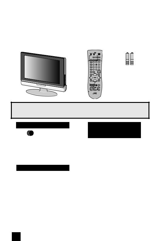
Thank you for your purchase of a JVC LCD Flat Television. Before you begin setting up your new television, please check to make sure you have all of the following items. In addition to this guide, your television box should include:
1 Television |
1 Remote Control |
||||
|
TV CATV VCR DVD |
POWER |
|||
|
MULTI SCREEN |
|
|
||
|
TWIN |
INDEX |
C.C. |
||
|
FREEZE SWAP |
SELECT |
INPUT |
||
|
DISPLAY |
1 |
|
2 |
3 |
|
|
|
|||
|
SLEEP TIMER |
4 |
|
5 |
6 |
|
|
|
|||
|
SOUND |
7 |
|
8 |
9 |
|
|
|
|||
|
VIDEO STATUS |
TUNE |
0 |
RETURN+ |
|
|
THEATER PRO ASPECT |
|
LIGHT |
||
|
MUTING |
|
|
|
OK |
|
|
CH + |
|
|
|
|
VOL |
|
|
|
VOL |
|
– |
|
|
|
+ |
|
|
CH – |
|
|
|
|
MENU |
|
|
|
BACK |
|
VCR CHANNEL |
VCR/DVD |
|
||
|
PREV NEXT |
POWER TV/VCR |
|||
|
REW |
PLAY |
|
FF |
|
|
REC |
STOP |
|
PAUSE |
|
|
OPEN/CLOSE |
|
|
STILL/PAUSE |
|
RM-C1257G
TV
Two AA
Batteries
Alkaline AA |
Alkaline AA |
Once you have unpacked your television, the next step is to connect it to your antenna/ cable or satellite system and to connect the audio/video devices you want to use with your television. To make these connections you will use plugs like the ones illustrated below.
Coaxial Cables
Used to connect an external antenna or cable TV system to your TV.
S-Video Cable
Used to make video connections with S-Video VCRs, Camcorders and DVD players.
Component Cables
Composite Cables
Audio Cables
Used to connect audio/ video devices like VCRs, DVD players, stereo amplifiers, game consoles, etc.
We recommend that before you start using your new television, you read your entire User’s Guide so you can learn about your new television’s many great features. If you’re anxious to start using your television right away, a quick setup guide follows on the next few pages.
8

Quick Setup |
TV Model |
|
|
NOTE: Before you connect your television to another device, please refer to the proper diagrams for your specific TV and remote. These will help assist you in understanding how to connect your television to another device, as well as use the remote to set up your television.
Rear Panel Diagram
|
S-VIDEO |
VIDEO |
|
|
|||
INPUT 1 |
R |
- |
AUDIO |
- |
L |
|
|
|
|
|
|||||
INPUT 2 |
S-VIDEO |
VIDEO |
|
|
|||
|
|
||||||
R |
- |
AUDIO |
- |
L |
|
|
|
|
|
||||||
|
|
||||||
|
|
|
|||||
|
|
|
|
VIDEO |
|
|
|
INPUT 3 |
|
|
|
|
|
|
|
|
R |
- |
AUDIO |
- |
L |
|
|
COMPONENT1 |
Pr |
|
|
|
Y |
|
|
INPUT |
|
|
|
|
Pb |
|
|
AUDIO |
R |
- |
AUDIO |
- |
L |
|
|
DIGITAL IN |
|
|
|
|
|
|
|
OUT |
R |
|
|
|
L |
|
|
AUDIO |
|
|
|
|
|
|
|
|
|
|
|
|
|
|
|
Side Panel Diagram
75Ω (UHF/VHF)
-IN DIGITAL
 POWER - VOLUME + - CHANNEL + MENU INPUT
9
Quick Setup |
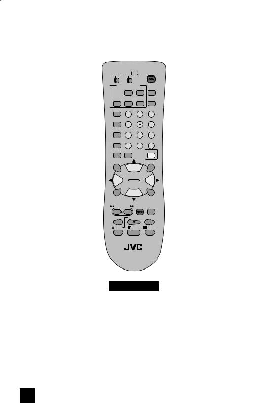
TV Remote Control |
|
|
TV CATV VCR DVD |
POWER |
|||
MULTI SCREEN |
|
|
||
|
TWIN |
INDEX |
C.C. |
|
FREEZE SWAP |
SELECT |
INPUT |
||
DISPLAY |
1 |
|
2 |
3 |
|
|
|||
SLEEP TIMER |
4 |
|
5 |
6 |
|
|
|||
SOUND |
7 |
|
8 |
9 |
|
|
|||
VIDEO STATUS TUNE |
0 |
RETURN+ |
||
THEATER PRO ASPECT |
|
|
LIGHT |
|
MUTING |
|
|
|
OK |
|
CH + |
|
|
|
VOL |
|
|
|
VOL |
–+
CH –
MENU |
BACK |
VCR CHANNEL |
VCR/DVD |
PREV NEXT |
POWER TV/VCR |
REW PLAY FF
REC |
STOP |
PAUSE |
 OPEN/CLOSE STILL/PAUSE
RM-C1257G
TV
RM-C1257G
Note:
• For information on remote control buttons, see pages 52 - 60.
10
Quick Setup |
Getting Started |
|
|
Getting Started
These quick setup pages will provide you, in three easy steps, with the basic information you need to begin using your new television right away.
If you have questions, or for more detailed information on any of these steps, please consult other sections of this manual.
Step 1 - Using the stand
This TV comes with a Table Top Stand already attached.
This stand can be used to adjust the direction of the TV screen 5° up, 10° down and 20° to the left or right.
Tilt the TV up or down
While holding the bottom of the stand with one hand, use your other hand to hold the middle of the top of the TV, and slowly tilt the TV up or down.
• As a safety measure, the stand is constructed so that it requires a certain amount of force to tilt the TV.
Rotate the TV left or right
While holding the bottom of the stand with one hand, use your other hand to hold the edge of the panel and slowly adjust the direction of the TV stand.
Cable Holder
A cable holder which keeps your connection cables tidy is attached on the back of the stand. Gently squeeze the left and right of the cable holder, and pull it to remove it from the stand. After putting the cables in the cable holder, attach it to the back of the stand again.
Cable Holder
11

Quick Setup |
Getting Started |
|
|
Step 2 – The Remote Control
Before you can operate your remote control, you first need to install the batteries (included).
Lift and pull the latch on the back of the remote control to open. Insert two batteries (included) carefully noting the “+” and “–” markings, placing the “–” end in the unit first. Snap the cover back into place.
When you change the batteries, try to complete the task within three minutes. If you take longer than three minutes, the remote control codes for your VCR, DVD, and/or cable box/satellite receiver may have to be reset. See pages 24 - 27.
Key Feature Buttons
The four key feature buttons at the center of the remote can be used for basic operation of the television. The top and bottom buttons will scan forward and back through the available channels. To move rapidly through the channels using JVC’s Hyperscan feature, press and hold CH+ or CH–. The channels will zip by at a rate of five channels per second. The right and left buttons will turn the volume up or down. These buttons are also marked with four arrows and are used with JVC’s onscreen menu system. To use the onscreen menus, press the MENU button.
MUTING |
OK |
|
CH + |
VOL |
VOL |
–+
CH –
MENU |
BACK |
Basic Operation
Turn the television on and off by pressing the POWER button at the top right corner of the remote. If this is the first time you are turning on the TV, the interactive plug-in menu appears.
•Make sure the TV/CATV switch is set to TV. Move the switch to CATV only if you need to operate a cable box.
•Slide the VCR/DVD selector switch to VCR to control a VCR. Slide to
DVD to control a DVD player. Please see pages 24 to 27 for instructions on programming your remote control to operate a cable box, VCR or DVD player.
POWER
TV CATV
VCR DVD
12

Quick Setup |
Connections |
|
|
Step 3 - Connecting your devices
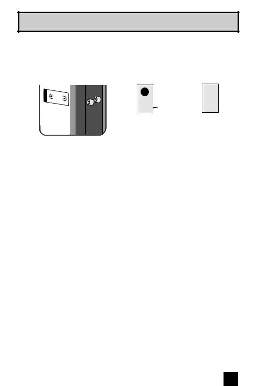
Remove the terminal cover
There are connection terminals behind the covers on the left and right in the back of the TV. Remove these two covers before connecting an antenna or other devices. The covers can be removed by removing the hooks. When replacing the covers, place the side of the covers against the TV and insert the hooks.
Note:
• Leave the terminal covers off if they do not fit properly. Do not force to replace the covers. Doing so may damage the connection cables and covers.
Connections
Please follow the flow chart below to determine which connection setup is right for you. Then, refer to the appropriate diagrams to connect your television to other devices that you may have. After you are finished connecting your devices, plug the power cord into the nearest power outlet and turn on the TV.
A VCR is not necessary for operation of the television. If you follow these diagrams and the television does not work properly, contact your local cable operator.
•To connect a DVD player, see Diagram #3. A DVD player is optional.
•If you have a satellite television system, please refer to the satellite TV manual.
Do you use a Cable TV Box?
Yes |
No |
Do you have a VCR? |
|
Do you have a VCR? |
|
|
|
Yes |
No |
Yes |
No |
Diagram #2 Diagram #1 |
Diagram #3 Diagram #1 |
13

Quick Setup |
Connections |
|
|
Diagram #1 Cable or Antenna
Output
Coaxial Cable
OR
IN OUT
Cable Box
Note:
75Ω (UHF/VHF)
TV Rear Panel
•If you do not have a cable box, connect the cable wire from the wall outlet into the back of the TV.
Diagram #2
Cable or Antenna
Output
Coaxial Cable
IN |
Two-Way |
OUT OUT |
Splitter |
Cable Box |
|
OUT IN |
|
S-VIDEO |
|
|
VIDEO |
||
|
|
|
|
|
|
INPUT 1 |
|
|
|
|
|
R |
|
- |
AUDIO |
|
- L |
|
|
|
|
||
S-VIDEO |
|
|
|
||
|
|
|
|
|
VIDEO |
INPUT 2 |
|
|
|
|
|
R |
- |
AUDIO |
- |
L |
|
|
|
||||
75Ω (UHF/VHF)
VCR
IN
IN
OUT |
TV Rear Panel |
V L R
OUT
 OR
OR
DIGITAL |
-IN |
Notes:
•If your VCR is a mono sound unit, it will have only one audio out jack. Connect it to the LEFT AUDIO INPUT on the rear of the TV.
•Use the S-Video connection if possible for superior picture quality.
•Your VCR must be turned on to view premium cable channels.
14

Quick Setup |
Connections |
|
|
Notes:
•Green, blue and red are the most common colors for DVD cables. Some models may vary colors. Please consult the user’s manual for your DVD player for more information.
•Be careful not to confuse the red DVD cable with the red audio cable. It is best to complete one set of connections (DVD or audio output) before starting the other to avoid accidentally switching the cables.
•You may also connect the DVD player to Input 1.
Diagram #3
Cable or Antenna
Output
Coaxial Cable
IN |
Two-Way |
OUT OUT |
Splitter |
|
IN |
R L V |
|
|
S-VIDEO |
|
|
|
|
|
VIDEO |
|||
|
IN |
|
|
|
|
|
|
|
|
|
|
|
|
|
OUT |
|
INPUT 1 |
|
|
|
|
|
|
|
|
|
|
|
|
|
|
R - |
AUDIO - L |
|
|
|
|
|
|
|
|
OUT |
|
|
|
|
|
|
VCR |
|
|
2 |
S-VIDEO |
|
|
|
OR |
|
|
VIDEO |
||
|
|
INPUT |
|
|
|
|
|
|
|
|
|
|
|
|
|
|
|
R |
- |
|
|
|
|
|
|
AUDIO - L |
|
|
|
|
|
|
|
VIDEO |
|
|
|
INPUT 3 |
|
|
|
|
|
|
|
R |
- |
|
|
|
|
|
|
AUDIO - L |
|
|
|
|
COMPONENT1 |
Pr |
|
Y |
|
|
|
INPUT |
|
|
Pb |
|
|
|
AUDIOINDIGITAL |
R - |
|
|
|
|
|
|
|
AUDIO - L |
|
OUT |
L |
|
R |
UDIO |
|
75Ω (UHF/VHF)
TV Rear Panel
DIGITAL |
-IN |
|
Y |
Green |
|
PB |
Blue |
AUDIO OUT |
PR |
Red |
|
|
|
R L |
OUT |
|
DVD Player (OPTIONAL)
15

Quick Setup |
Connections |
|
|
Connecting to a Camcorder
You can connect a camcorder to you televison by using the input jacks located on the back of the television.
TV Rear Panel
CAMCORDER
 OR
OR
S-VIDEO |
|
|
VIDEO |
||
|
|
|
|
|
|
INPUT 1 |
|
|
|
|
|
R |
|
- |
AUDIO |
|
- L |
|
|
|
|
||
S-VIDEO |
|
|
|
||
|
|
|
|
|
VIDEO |
INPUT 2 |
|
|
|
|
|
R |
- |
AUDIO |
- |
L |
|
|
|
||||
|
|
|
|
|
VIDEO |
INPUT 3 |
|
|
|
|
|
R |
- AUDIO |
|
|
||
1)Connect a yellow composite cable from the camcorder VIDEO OUT, into the VIDEO IN on the back of the TV, OR connect an S-Video cable from the camcorder to the back of the TV.
2)Connect a white cable from the camcorder LEFT AUDIO OUT, into the LEFT AUDIO IN on the back of the TV.
3)Connect a red cable from the camcorder RIGHT AUDIO OUT, into the RIGHT AUDIO IN on the back of the TV.
Note:
•If your camcorder is a mono sound model it will have only one AUDIO OUT. Connect it to the LEFT AUDIO IN on the back of the TV.
Headphone Connection
You can connect a pair of headphones to the television using the headphone jack located on the side of the television.
1) Plug a headphone jack into the headphone jack on the television’s side panel.
16
Quick Setup |
Connections |
Connecting to an External Amplifier
AUDIO OUT
R
TV Rear Panel
Speaker |
Speaker |
Amplifier
L
1)Connect a white cable from the LEFT AUDIO OUTPUT on the back of the TV to the LEFT AUDIO INPUT on the amplifier.
2)Connect a red cable from the RIGHT AUDIO OUTPUT on the back of the TV to the RIGHT AUDIO INPUT on the amplifier.
Notes:
•Refer to your amplifier’s manual for more information.
•You can use AUDIO OUTPUT for your home theater system.
•DVI analog sound can not be outputted.
17

Quick Setup |
Connections |
|
|
Connecting to an AV Receiver using your television's V1 Smart Input
By connecting your AV Receiver to your television's V1 Smart Input, you can watch picture sources from many different devices, without having to change or use the other input connections on your TV. This allows you to free up the other input connections so you can connect more devices to your television.
TV Rear Panel
DIGITAL IN AUDIO INPUT 1 COMPONENT INPUT 3 INPUT 2 INPUT 1
S-VIDEO |
|
VIDEO |
|||
|
|
|
|
||
R |
|
- |
AUDIO |
- |
L |
S-VIDEO |
|
|
|
||
|
|
|
|
VIDEO |
|
R |
- |
AUDIO |
- |
L |
|
|
|
||||
|
|
|
|
VIDEO |
|
R |
- |
AUDIO |
- |
L |
|
|
|
|
|
|
Y |
Pr |
|
|
|
|
Pb |
|
|
|
|
|
|
R |
- |
AUDIO |
- |
L |
|
AV Receiver
MONITOR |
Y |
|
OUT |
||
|
||
|
PB |
|
|
PR |
|
|
MONITOR OUT |
AUDIO OUT
R
L
1)Connect an S-Video Cable from the AV Receiver's MONITOR OUT, to the S-Video INPUT-1 on the back of your television.
2)Connect a Yellow Composite Cable from the AV Receiver's MONITOR OUT, into the VIDEO INPUT-1 on the back of your television.
3)Connect a Green Component Cable from the AV Receiver's Y MONITOR OUT, into the Y VIDEO INPUT-1 on the back of your television.
4)Connect a Blue Component Cable from the AV Receiver's PB MONITOR OUT, into the Pb VIDEO INPUT-1 on the back of your television.
5)Connect a Red Component Cable from the AV Receiver's PR MONITOR OUT, into the Pr VIDEO INPUT-1 on the back of your television.
Notes:
•Please refer to your AV Receiver instruction manual for more information on connecting your speakers and other devices like a DVD player.
•Use your AV Receiver's remote to switch to the different devices you have connected.
•Some AV Receivers may not respond when the V1 Smart Input function is turned on.
•If you have video connections for each input device connected to your AV Receiver, you should not connect them using both S-Video and Composite connection at the same time when you are using V1 Input as the V1 Smart Input. In this case we recommend using the S-Video connection.
18

Quick Setup |
Connections |
|
|
Connecting to a Digital TV Receiver
By connecting a Digital TV Receiver, high definition pictures can be displayed on your TV in their digital form.
75Ω (UHF/VHF)
TV Rear Panel
-IN DIGITAL
|
INPUT |
|
R - |
|
AUDIO - L |
|
TV Rear Panel |
DTV Decoder |
VIDEO |
3 |
|
|
INPUT |
|
R - |
|
AUDIO - L |
DIGITAL OUT |
AUDIO OUT |
L R
COMPONENT1 |
Pr |
|
|
|
Y |
INPUT |
|
|
|
|
Pb |
AUDIO |
R |
- |
AUDIO |
- |
L |
DIGITAL IN |
|
|
|
|
|
OUT |
R |
|
|
|
L |
AUDIO |
|
|
|
|
|
HDMI to DVI Cable
After the connections have been made, tighten the screw to secure the cables.
1)Connect the HDMI to DVI Cable from the DIGITAL OUT on the back of your DTV decoder, to the DIGITAL-IN on the back of your television.
2)Connect a red cable from the DTV decoder RIGHT AUDIO OUT, to the RIGHT AUDIO DIGITAL-IN on the back of your television.
3)Connect a white cable from the DTV decoder LEFT AUDIO OUT, to the LEFT AUDIO DIGITAL-IN on the back of your television.
•The digital-in terminal is not compatible with the picture signal of a personal computer.
•Use a HDMI to DVI cable (commercially available) in order to digitally connect the television with a DTV decoder.
Notes:
•If 480p signals (640x480 or 720x480) are displayed on the screen, the horizontal balance may be slightly shifted. Access the “DIGITAL-IN” in the initial setup menu to adjust it. (Refer to page 45.)
•When you do the above connection, set DIGITAL-IN AUDIO in the Initial Setup menu to ANALOG. See "DIGITAL-IN AUDIO", page 45.
19

Quick Setup |
Connections |
|
|
Connecting to a HDMI Compatible Device
By connecting a HDMI compatible device, high definition pictures can be displayed on your TV in their digital form. Some HDMI devices can include DVD players, D-VHS or any HDMI compatible device.
HDMI (High Definition Multimedia Interface) is the first industry supported, uncompressed, all digital audio/video interface. HDMI provides and interface between any audio/video source, such as a set-top box, DVD player, A/V receiver or an audio and/or video monitor, such as a digital television (DTV).
HDMI Compatible Device
75Ω (UHF/VHF)
DIGITAL OUT |
AUDIO OUT |
L R
DIGITAL-IN |
HDMI Cable
1)Connect the HDMI Cable from the DIGITAL OUT on the back of your DTV or HDMI device, to the DIGITAL-IN on the back of your television.
Note:
•When you do the above connection, set DIGITAL-IN AUDIO in the Initial Setup menu to DIGITAL. See "DIGITAL-IN AUDIO", page 45.
20
Quick Setup |
Plug-In Menu |
|
|
Step 4 – The Interactive Plug In Menu
When you turn your television on for the first time the interactive plug-in menu will appear. The plug-in menu helps you to get your TV ready to use by letting you set your preferences for:
•The language in which you want the onscreen menus to appear.
•Setting the TV’s clock to the correct time so your timer functions will work properly. You can choose “AUTO” or “MANUAL” for setting the clock.
•The auto tuner setup of which channels you wish to receive.
We recommend you complete the interactive plug-in items before you start using your television.
Notes:
•The interactive plug-in menu setting does not appear if your TV has been turned on before. In this case use the onscreen menus to perform these settings. See pages 40, 50, 31.
•If you press the Menu button while setting up the interactive plug-in menu, it will skip over it.
Language
After the “JVC INTERACTIVE PLUG IN MENU” has been displayed, the TV automatically switches to the LANGUAGE settings. You can choose to view your onscreen menus in three languages: English, French (Français) or Spanish (Español).
LANGUAGE/LANGUE/IDIOMA |
|
|
|
|
|
|
|
|
ENGLISH |
|
|
|
NEXT |
|
|
|
|
|
|
|
SELECT OPERATE |
MENU EXIT |
|
√® To choose a language: (English, Français or Español)
†To NEXT (To set clock)
(To be continued...)
21
Quick Setup |
Plug-In Menu |
|
|
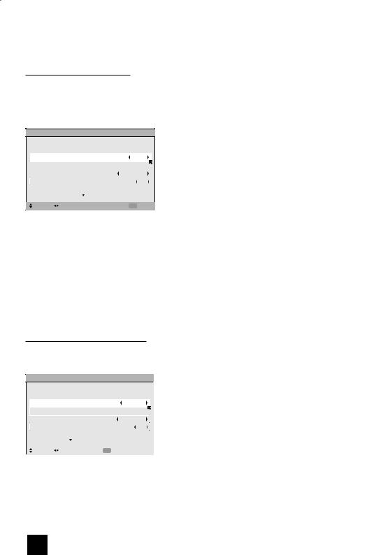
Auto Clock Set
Before you use any of your TV’s timer functions, you must first set the clock. You may precisely set your clock using the XDS time signal broadcast by most public broadcasting stations. If you do not have this in your area, you will have to set the clock manually. See manual clock set below. To set the clock using the XDS signal:
SET CLOCK
|
MODE |
AUTO |
|
|
TIME |
-- : -- -- |
|
|
TIME ZONE |
ATLANTIC |
|
|
D.S.T. |
ON |
|
|
|
NEXT |
|
|
|
|
|
|
SELECT OPERATE |
MENU EXIT |
|
Notes:
è To choose AUTO
†To TIME ZONE
è To select your time zone: (Atlantic, Eastern, Central, Mountain, Pacific, Alaska or Hawaii)
†To move to D.S.T. (Daylight Savings Time) √® To turn D.S.T. ON or OFF
†To NEXT (To Auto Tuner Setup)
•D.S.T. can be used only for US and Canada when it is set to ON in the SET CLOCK menu.
•Only when the MODE set to AUTO, the Daylight Savings Time feature automatically adjusts your TV’s clock for Daylight Savings. The clock will move forward one hour at 2:00 am on the first Sunday in April. The clock will move back one hour at 2:00 am on the last Sunday in October.
•You will have to reset the clock after a power interruption. You must set the clock before operating any timer functions.
Manual Clock Set
To set your clock manually (without using the XDS signal), choose MANUAL. If you choose AUTO, see auto clock set above.
SET CLOCK
|
MODE |
|
MANUAL |
|
|
TIME |
|
-- : -- -- |
|
|
TIME ZONE |
|
ATLANTIC |
|
|
D.S.T. |
|
ON |
|
|
|
START CLOCK |
|
|
|
|
|
|
|
|
SELECT |
OPERATE |
MENU EXIT |
|
Note:
è To choose MANUAL
†To TIME
è To set the hour
†To minute
è To set the minute
†To Start Clock
•You will have to reset the clock after a power interruption. You must set the clock before operating any timer functions.
(To be continued...)
22
 Loading...