


 Loading...
SERVICE MANUAL
LCD FLAT TELEVISION
LT-17S2 LT-17S2 LT-17S2
/S
/A
TABLE OF CONTENTS
1. |
PRECAUTIONS .......................................................................................................................................... |
1-3 |
2. |
SPECIFICSERVICEINSTRUCTIONS .......................................................................................................... |
1-5 |
3. |
DISASSEMBLY ........................................................................................................................................... |
1-6 |
4. |
ADJUSTMENT .......................................................................................................................................... |
1-22 |
5. |
TROUBLESHOOTING .............................................................................................................................. |
1-23 |
COPYRIGHT © 2004 Victor Company of Japan, Limited
No.YA033
2004/9

|
|
|
SPECIFICATION |
|
|
|
|
Items |
|
Contents |
|
|
|
|
|
Dimentions (W x H x D) |
|
46.5cm x 32.5cm x 7.8cm (TV only) |
|
|
|
|
46.5cm x 36.3cm x 19.0cm |
Mass |
|
6.1kg (TV only) |
|
|
|
|
7.3kg |
TV RF System |
|
B, G, I, D, K |
|
Colour System |
|
TV Mode |
PAL / SECAM |
|
|
Video Mode |
PAL / SECAM / NTSC3.58 / NTSC4.43 |
Stereo System |
|
A2(B/G, D/K), NICAM (B/G, I, D/K, L) |
|
Teletext System |
|
FLOP(Fastext), WST(World Standard System) |
|
Receiving Frequency |
|
|
E2 ~ E12, E21 ~ E69 |
|
|
|
S1 ~ S41, X, Y, Z, Z+1, Z+2 |
|
|
ITALY |
A-H, H+1, H+2 |
|
|
|
F2 ~ F10, F21 ~ F69 |
|
|
|
R1 ~ R12, R21 ~ R69 |
|
|
IR |
A ~ J |
|
|
French cable TV |
116MHz ~ 172MHz |
|
|
|
220MHz ~ 469MHz |
Aerial Input Terminal |
|
75Ω unbalanced |
|
Power Input |
|
TV : 12V DC, AC adapter : AC100V ~ AC240V, 50Hz/60Hz |
|
Power Consumption |
|
60W, Standby : 3W |
|
Display area |
|
Visible size: 43.5cm (Diagonal) / 37.0cm x 22.5cm (H x V) |
|
Display pixels |
|
1280 x 768 (W-XGA) |
|
Speakers |
|
5.4cm, Round type x 2 |
|
Audio Output |
|
3W + 3W |
|
Video / Audio Inputs |
|
VIDEO-1 terminal |
Composite video, S-VIDEO, Audio L, R |
(1/2) |
|
VIDEO-2 terminal |
Component video, Audio L, R |
Audio Outputs |
|
RCA connectors x3 |
|
|
|
|
Audio L, R, Subwoofer |
PC Input |
|
Analog RGB : D-SUB(15pin) x1, PC AUDIO IN x1 |
|
Headphone |
|
3.5mm stereo mini jack x 1 |
|
Remote Control Unit |
|
DA-5000100084 |
|
|
|
|
(AA/R06/UM-3 battery x 2) |
AC adapter |
|
HP-OL060D031 |
|
NOTE: Design & specifications are subject to change without notice.
1-2 (No. YA033)

SECTION 1 PRECAUTION
1.1 SAFETY PRECAUTIONS
(1)The design of this product contains special hardware, many circuits and components specially for safety purposes. For continued protection, no changes should be made to the original design unless authorized in writing by the manufacturer. Replacement parts must be identical to those used in the original circuits. Service should be performed by qualified personnel only.
(2)Alterations of the design or circuitry of the products should not be made. Any design alterations or additions will void the manufacturer's warranty and will further relieve the manufacturer of responsibility for personal injury or property damage resulting therefrom.
(3)Many electrical and mechanical parts in the products have special safety-related characteristics. These characteristics are often not evident from visual inspection nor can the protection afforded by them necessarily be obtained by using replacement components rated for higher voltage, wattage, etc. Replacement parts which have these special safety characteristics are identified in the parts list of Service manual. Electrical components
having such features are identified by shading on the schematics and by ( ) on the parts list in Service manual. The use of a substitute replacement which does not have the same safety characteristics as the recommended replacement part shown in the parts list of Service manual may cause shock, fire, or other hazards.
(4)Don't short between the LIVE side ground and ISOLATED (NEUTRAL) side ground or EARTH side ground when repairing.
Some model's power circuit is partly different in the GND. The difference of the GND is shown by the LIVE : (  ) side GND, the ISOLATED (NEUTRAL) : (
  ) side GND and
EARTH : (  ) side GND. Don't short between the LIVE side GND and ISOLATED (NEUTRAL) side GND or EARTH side GND and never measure the LIVE side GND and ISOLATED (NEUTRAL) side GND or EARTH side GND at the same time with a measuring apparatus (oscilloscope etc.).
If above note will not be kept, a fuse or any parts will be broken.
(5)If any repair has been made to the chassis, it is recommended that the B1 setting should be checked or adjusted (See ADJUSTMENT OF B1 POWER SUPPLY).
(6)The high voltage applied to the picture tube must conform with that specified in Service manual. Excessive high voltage can cause an increase in X-Ray emission, arcing and possible component damage, therefore operation under excessive high voltage conditions should be kept to a minimum, or should be prevented. If severe arcing occurs, remove the AC power immediately and determine the cause by visual inspection (incorrect installation, cracked or melted high voltage harness, poor soldering, etc.). To maintain the proper minimum level of soft X-Ray emission, components in the high voltage circuitry including the picture tube must be the exact replacements or alternatives approved by the manufacturer of the complete product.
(7)Do not check high voltage by drawing an arc. Use a high voltage meter or a high voltage probe with a VTVM. Discharge the picture tube before attempting meter
connection, by connecting a clip lead to the ground frame and connecting the other end of the lead through a 10kΩ 2W resistor to the anode button.
(8)When service is required, observe the original lead dress. Extra precaution should be given to assure correct lead dress in the high voltage circuit area. Where a short circuit has occurred, those components that indicate evidence of overheating should be replaced. Always use the manufacturer's replacement components.
(9)Isolation Check
(Safety for Electrical Shock Hazard)
After re-assembling the product, always perform an isolation check on the exposed metal parts of the cabinet (antenna terminals, video/audio input and output terminals, Control knobs, metal cabinet, screw heads, earphone jack, control shafts, etc.) to be sure the product is safe to operate without danger of electrical shock.
a)Dielectric Strength Test
The isolation between the AC primary circuit and all metal parts exposed to the user, particularly any exposed metal part having a return path to the chassis should withstand a voltage of 3000V AC (r.m.s.) for a period of one second. (. . . . Withstand a voltage of 1100V AC (r.m.s.) to an appliance rated up to 120V, and 3000V AC (r.m.s.) to an appliance rated 200V or more, for a period of one second.) This method of test requires a test equipment not generally found in the service trade.
b)Leakage Current Check
Plug the AC line cord directly into the AC outlet (do not use a line isolation transformer during this check.). Using a "Leakage Current Tester", measure the leakage current from each exposed metal part of the cabinet, particularly any exposed metal part having a return path to the chassis, to a known good earth ground (water pipe, etc.). Any leakage current must not exceed 0.5mA AC (r.m.s.).
However, in tropical area, this must not exceed 0.2mA AC (r.m.s.).
Alternate Check Method
Plug the AC line cord directly into the AC outlet (do not use a line isolation transformer during this check.). Use an AC voltmeter having 1000 ohms per volt or
more sensitivity in the following manner. Connect a 1500Ω 10W resistor paralleled by a 0.15µF AC-type capacitor between an exposed metal part and a known good earth ground (water pipe, etc.). Measure the AC voltage across the resistor with the AC voltmeter. Move the resistor connection to each exposed metal part, particularly any exposed metal part having a return path to the chassis, and measure the AC voltage across the resistor. Now, reverse the plug in the AC outlet and repeat each measurement. Any voltage measured must not exceed 0.75V AC (r.m.s.). This corresponds to 0.5mA AC (r.m.s.).
However, in tropical area, this must not exceed 0.3V AC (r.m.s.). This corresponds to 0.2mA AC (r.m.s.).
AC VOLTMETER (HAVING 1000Ω/V,
OR MORE SENSITIVITY)
0.15µF AC-TYPE |
|
|
|
PLACE THIS PROBE |
|
1500Ω 10W |
ON EACH EXPOSED |
|
METAL PART |
||
|
GOOD EARTH GROUND
(No. YA033) 1-3
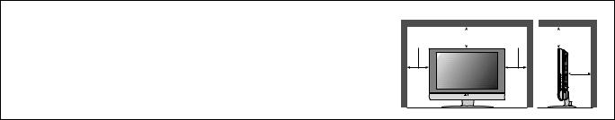
1.2 INSTALLATION 1.2.1 HEAT DISSIPATION
If the heat dissipation vent behind this unit is blocked, cooling efficiency may deteriorate and temperature inside the unit will rise. Therefore, please make sure pay attention not to block the heat dissipation vent as well as the ventilation outlet behind the unit and ensure that there is room for ventilation around it.
1.2.2 INSTALLATION REQUIREMENTS
Ensure that the minimal distance is maintained, as specified below, between the unit with and the surrounding walls. Install the unit on stable flooring or stands.
Take precautionary measures to prevent the unit from tipping in order to protect against accidents and earthquakes.
Distance recommendations
Avoid improper installation and never position the unit where good ventilation is impossible.
When installing this TV, distance recommendations must be maintained between the set and the wall, as well as inside a tightly enclosed area or piece of furniture.
Keep to the minimum distance guidelines shown for safe operation.
150 mm |
200 mm |
150 mm |
200 mm |
|
|
50 mm
1.3PRECAUTIONS
(1)Depending on the around temperature, the brightness leaning occurs. Be careful of the environment in the product installation place and so on sufficiently.
(2)Don't hinder radiation from the back, the heaven and the side. Please refer to the next page that explains about the condition of the installation.
The inside becomes hot if hindering radiation and there is fear, which the inner circuit damages.
(3)Install in the place with good ventilation. Use in the condition that around temperature is in the 0~35°C range.
(4)Avoid preservation and use at the high temperature or high humidity place. If you behave like this, leaning sometimes happens in the screen when the set actives.
(5)Depending on the condition and the environment of display, the slight fleck of the light and leaning of the screen and so on is sometimes conspicuous. This is the characteristic which is peculiar to liquid crystal display. It is not set trouble.
(6)This monitor has cool cathode pipe as the backlight. The time change and the use time sometimes change brightness and condition of display.
1.4THE ATTENTION IN TRANSPORTATION
When transporting a set, if the load handling is bad (throwing, falling and so on) however it is using a solid box, pressure inside liquid crystal display.
In the case there is fear to break the liquid crystal display while transporting. To prevent from the accident or trouble while transporting, pay attention to choice of the transportation company sufficiently and also arrange for it in the delivery after the attention of the load handling is explained to the transportation company.
This set is used glass for composing liquid crystal display. When carrying, pay attention not to add over vibration and impact sufficiently.
Ensure that it is placed upright and not horizontally during transportation and storage as the LCD panel is very vulnerable to lateral impacts and may break. During transportation, ensure that the unit is loaded along the traveling direction of the vehicle, and avoid stacking them on one another. For storage, ensure that they are stacked in 2 layers or less even when placed upright.
1-4 (No. YA033)
SECTION 2
SPECIFIC SERVICE INSTRUCTIONS
2.1 DESCRIPTION ABOUT LIQUID CRYSTAL PANEL 2.2.1 STRUCTURE OF LIGUID CRYSTAL PANEL
The Liquid Crystal Panel of this model is TFT Panel. The Print circuit board that consist of TFT array and the print circuit board adopted stripe shaped image element alignment are used. These two boards are mixed. The Liquid crystal is enclosed between two boards.
2.1.2 LONG RANGEAFTERIMAGE OF LIQUID CRYSTAL
The small amount of ion material has mixed a liquid crystal panel with the liquid crystal material in the manufacturing process. If ion material is piled up partially among the poles when the voltage is impressed among the poles, the brightness difference occurs and becomes a long-range afterimage If same picture is reflected for long time, such a long-range afterimage occurs. If the long-range afterimage occurs, we recommend that you reflect the single color image or moving picture and so on to restore.
2.1.3 THE DISPLAY REPLYING SPEED OF LIQUID CRYSTAL
Because the speed to display of Liquid crystal panel is slower than the speed of the CRT monitor, some of the moving picture cannot overtake to the speed to display and the image looks flowing is sometimes displayed. This is not trouble, but efficiency of Liquid Crystal.
2.1.4 THE EYESIGHT CORNER OF LIQUID CRYSTAL
The liquid crystal panel has the wide eyesight corner for which it is difficult to reverse brightness. The tint changes depending on the direction to see a screen. This is not trouble, but efficiency of Liquid Crystal.
2.1.5 THE PICTURE ELEMENT FAULT OF LIQUID CRYSTAL
The liquid crystal panel is composed of precise technique but all devices don't always work right.
2.2 ATTENTION ITEMS WHEN REPLACING PARTS
2.2.1 ATTENTION TO EXCHANGE THE LIQUID CRYSTAL PANEL
(1)The stillness electricity sometimes makes damage a liquid crystal panel. In liquid crystal panel exchange, do a measure of the stillness electricity such as the earth band.
(2)A liquid crystal panel and back-light are made from glass. If you gain an impact to these materials, there is fear to damage. So in case of treatment, be careful sufficiently.
(3)Fix with the screw after confirming that there is not a float to chassis base when exchanging liquid crystal panel. After that reflect all the black signals and confirm that brightness leaning doesn't occur near the screw fixation part. When brightness leaning occurs, slacken a screw in the neighborhood until the brightness leaning is running-out.
(4)Fix the torque that installs a screw below 0.294Nm.
If you install at any more torque, the liquid crystal panel is transformed and sometimes damages.
(5)If you pull out or insert each connector when power is ON, it causes the trouble.
So pull out or insert each connector in the condition to have pulled out a power supply plug.
2.2.2 ATTENTION WHEN EXCHANGING THE FUSE
When exchanging the fuse, please use specified parts. After fuse exchange, confirm that insulater is set to the shield and insulate surely.
(No. YA033) 1-5

SECTION 3
DISASSEMBLY
3.1 DISASSEMBLY PROCEDURE CAUTION:
•Disconnect the set and attached devices from the electrical outlet
•To avoid ESD (Electro-Static Discharge), ground yourself by using a wrist grounding strap or by periodically touching unpainted metal on the set.
3.1.1 REMOVING THE CABLE COVER AND NECK COVER
(1)Remove the CABLE COVER (L) by pulling the snap tabs.
(2)Make similar ways to remove the CABLE COVER (R) and NECK COVER.
Snap tabs |
CABLE COVER (L) |
CABLE COVER (R) |
NECK COVER |
REAR COVER |
1-6 (No. YA033)

3.1.2 REMOVING THE DUMMY COVERS (If necessary)
(1) Remove the DUMMY COVERS of TUNER module and AV JACK module by pulling the snap tabs
Snap tab |
DUMMY COVER |
||
|
|
|
|
Snap tab |
DUMMY COVER TUNER COVER |
TUNER module
AV JACK module
(No. YA033) 1-7
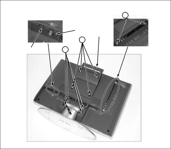
3.1.3 PREPARING TO REMOVE THE MODULE UNITS
(1)Remove the TUNER module cover by pulling snap tab.
(2)Loosen 2 screws [A] of AV JACK module.
3.1.4 REMOVING THE BASE AND THE HANDLE
(1)Remove 4 screws [B] and remove the BASE by pulling BASE.
(2)Remove 4 screws [C] and remove the HANDLE.
A
TUNER module
HANDLE
C
Snap tab |
B |
|
1-8 (No. YA033)
Loading...