


KWAVX-624-UI
JVC KWAVX-624-UI, KWADV-792-J, KWAVX-625-EU, KWAVX-625-U, KWAVX-625-UT Service manual
...
SERVICE MANUAL
DVD RECEIVER WITH MONITOR
MA443<Rev.001>20094SERVICE MANUAL
KW-ADV792J, KW-AVX624UI, KW-AVX625U,
KW-AVX625UT, KW-AVX625EU, KW-AVX626U,
KW-AVX626UT, KW-AVX626EU, KW-AVX626A,
KW-AVX720J, KW-AVX720E, KW-AVX720EE,
KW-AVX724UI, KW-AVX725U, KW-AVX725UN,
KW-AVX725UT, KW-AVX725EU, KW-AVX726U,
KW-AVX726UN, KW-AVX726UT, KW-AVX726EU,
KW-AVX726A, KW-AVX728UF
only KW-ADV792/KW-AVX720J
COPYRIGHT © 2009 Victor Company of Japan, Limited
Lead free solder used in the board (material : Sn-Ag-Cu, melting point : 219 Centigrade)
Lead free solder used in the board (material : Sn-Cu, melting point : 230 Centigrade)
TABLE OF CONTENTS
1 PRECAUTION. . . . . . . . . . . . . . . . . . . . . . . . . . . . . . . . . . . . . . . . . . . . . . . . . . . . . . . . . . . . . . . . . . . . . . . . . 1-7
2 SPECIFIC SERVICE INSTRUCTIONS . . . . . . . . . . . . . . . . . . . . . . . . . . . . . . . . . . . . . . . . . . . . . . . . . . . . . 1-10
3 DISASSEMBLY . . . . . . . . . . . . . . . . . . . . . . . . . . . . . . . . . . . . . . . . . . . . . . . . . . . . . . . . . . . . . . . . . . . . . . 1-10
4 ADJUSTMENT . . . . . . . . . . . . . . . . . . . . . . . . . . . . . . . . . . . . . . . . . . . . . . . . . . . . . . . . . . . . . . . . . . . . . . . 1-19
5 TROUBLESHOOTING . . . . . . . . . . . . . . . . . . . . . . . . . . . . . . . . . . . . . . . . . . . . . . . . . . . . . . . . . . . . . . . . . 1-32
COPYRIGHT © 2009 Victor Company of Japan, Limited
except KW-AVX626/KW-AVX625/KW-AVX624only KW-AVX726/KW-AVX725 E,EE
No.MA443<Rev.001>
2009/4
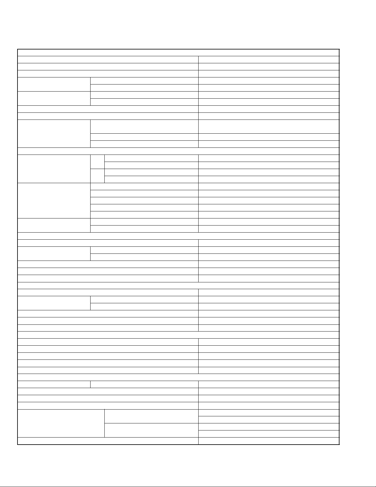
SPECIFICATION
KW-ADV792/KW-AVX720J
AMPLIFIER
Power Output 20 W RMS × 4 Channels at 4 Ω and < or = 1% THD+N
Signal-to-Noise Ratio 80 dBA (reference: 1 W into 4 Ω)
Load Impedance 4 Ω (4 Ω to 8 Ω allowance)
Equalizer Control Range Frequencies 60 Hz, 150 Hz, 400 Hz, 1 kHz, 2.5 kHz, 6.3 kHz, 15 kHz
Level ±10 dB
Audio Output Level
LINE OUT (REAR) and SUBWOOFER
Color System NTSC
Video Output (composite) 1 Vp-p/75 Ω
Other Terminals Input LINE IN, VIDEO IN, Antenna input, USB input, Steering
Frequency Range FM
FM Tuner Usable Sensitivity 9.3 dBf (0.8 µV/75 Ω)
AM Tuner Sensitivity 20 µV
Signal Detection System Non-contact optical pickup (semiconductor laser)
Frequency Response DVD, fs=48 kHz/96 kHz 16 Hz to 22 000 Hz
Dynamic Range 96 dB
Signal-to-Noise Ratio 98 dB
Wow and Flutter Less than measurable limit
USB Standards USB 2.0 Full Speed
Data Transfer Rate Full Speed Maximum 12 Mbps
Compatible Device Mass storage class
Compatible File System FAT 32/16/12
Max. Current DC 5 V 500 mA
Screen Size 7 inch wide liquid crystal display
Number of Pixel 336 960 pixels: 480 × 3 (horizontal) × 234 (vertical)
Drive Method TFT (Thin Film Transistor) active matrix format
Color System NTSC/PAL
Aspect Ratio 16:9 (wide)
Power Requirement Operating Voltage DC 14.4 V (11 V to 16 V allowance)
Grounding System Negative ground
Allowable Storage Temperature -10°C to +60°C (14°F to 140°F)
Allowable Operating Temperature 0°C to +40°C (32°F to 104°F)
Dimensions (W × H × D)
With trim plate and sleeve attached
Mass (approx.) 3.3 kg (7.3 lbs) (including trim plate and sleeve)
Line-Out Level/Impedance 2.5 V/20 kΩ load (full scale)
Output Impedance 1 kΩ
wheel remote input
Output VIDEO OUT
Others CD changer, DIGITAL OUT (optical)
TUNER SECTION
with channel interval set to 100 kHz or 200 kHz
with channel interval set to 50 kHz 87.5 MHz to 108.0 MHz
AM with channel interval set to 10 kHz 530 kHz to 1 710 kHz
with channel interval set to 9 kHz 531 kHz to 1 602 kHz
50 dB Quieting Sensitivity 16.3 dBf (1.8 µV/75 Ω)
Alternate Channel Selectivity (400 kHz) 65 dB
Frequency Response 40 Hz to 15 000 Hz
Stereo Separation 40 dB
Selectivity 40 dB
DVD/CD
VCD/CD 16 Hz to 20 000 Hz
USB
Low Speed Maximum 1.5 Mbps
MONITOR
GENERAL
Installation Size (approx.) 182 mm × 111 mm × 161 mm
Panel Size (approx.) 188 mm × 117 mm × 22 mm
87.5 MHz to 107.9 MHz
(7-3/16” × 4-3/8” × 6-3/8”)
(7-7/16” × 4-5/8” × 7/8”)
Design and specifications are subject to change without notice.
1-2 (No.MA443<Rev.001>)
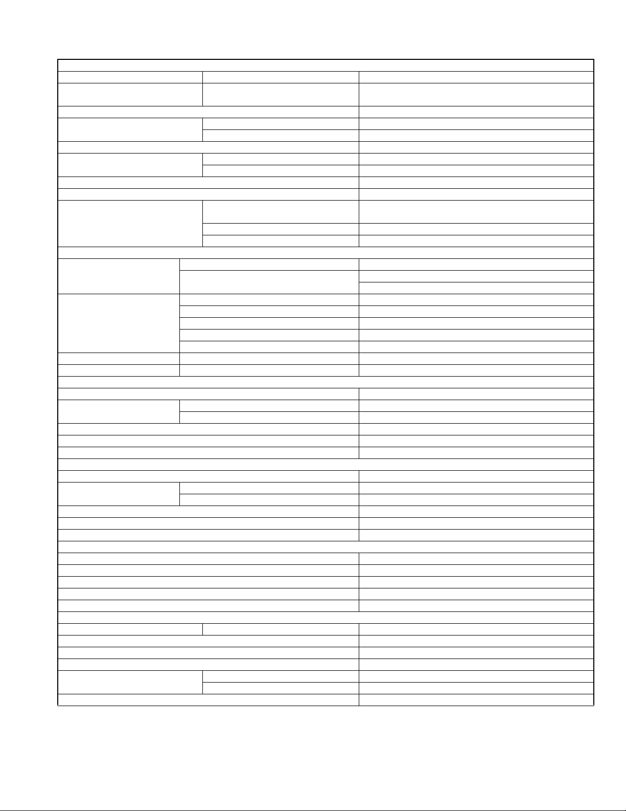
KW-AVX720E
AMPLIFIER
Maximum Power Output Front/Rear 50 W per channel
Continuous Power Output (RMS) Front/Rear 20 W per channel into 4 Ω, 40 Hz to 20 000 Hz at no more
than 1.0% total harmonic distortion
Load Impedance 4 Ω (4 Ω to 8 Ω allowance)
Equalizer Control Range Frequencies 60 Hz, 150 Hz, 400 Hz, 1 kHz, 2.5 kHz, 6.3 kHz, 15 kHz
Level ±10 dB
Signal-to-Noise Ratio 70 dB
Audio Output Level
LINE OUT (REAR) and SUBWOOFER
Color System PAL
Video Output (composite) 1 Vp-p/75 Ω
Other Terminals Input LINE IN, VIDEO IN, Aerial input, USB input, Steering
Frequency Range FM 87.5 MHz to 108.0 MHz
FM Tuner Usable Sensitivity 9.3 dBf (0.8 µV/75 Ω)
MW Tuner Sensitivity/Selectivity 20 µV/40 dB
LW Tuner Sensitivity 50 µV
Signal Detection System Non-contact optical pickup (semiconductor laser)
Frequency Response DVD, fs=48 kHz/96 kHz 16 Hz to 22 000 Hz
Dynamic Range 96 dB
Signal-to-Noise Ratio 98 dB
Wow and Flutter Less than measurable limit
USB Standards USB 2.0 Full Speed
Data Transfer Rate Full Speed Maximum 12 Mbps
Compatible Device Mass storage class
Compatible File System FAT 32/16/12
Max. Current DC 5 V 500 mA
Screen Size 7 inch wide liquid crystal display
Number of Pixel 336 960 pixels: 480 × 3 (horizontal) × 234 (vertical)
Drive Method TFT (Thin Film Transistor) active matrix format
Color System NTSC/PAL
Aspect Ratio 16:9 (wide)
Power Requirement Operating Voltage DC 14.4 V (11 V to 16 V allowance)
Grounding System Negative ground
Allowable Storage Temperature -10°C to +60°C
Allowable Operating Temperature 0°C to +40°C
Dimensions (W × H × D)
With trim plate and sleeve attached
Mass (approx.) 3.3 kg (including trim plate and sleeve)
Line-Out Level/Impedance 2.5 V/20 kΩ load (full scale)
Output Impedance 1 kΩ
wheel remote input
Output VIDEO OUT
Others CD changer, DIGITAL OUT (optical)
FM/AM TUNER
AM (MW) 522 kHz to 1 620 kHz
(LW) 144 kHz to 279 kHz
50 dB Quieting Sensitivity 16.3 dBf (1.8 µV/75 Ω)
Alternate Channel Selectivity (400 kHz) 65 dB
Frequency Response 40 Hz to 15 000 Hz
Stereo Separation 40 dB
DVD/CD
VCD/CD 16 Hz to 20 000 Hz
USB
Low Speed Maximum 1.5 Mbps
MONITOR
GENERAL
Installation Size (approx.) 182 mm × 111 mm × 161 mm
Panel Size (approx.) 188 mm × 117 mm × 22 mm
Design and specifications are subject to change without notice.
(No.MA443<Rev.001>)1-3
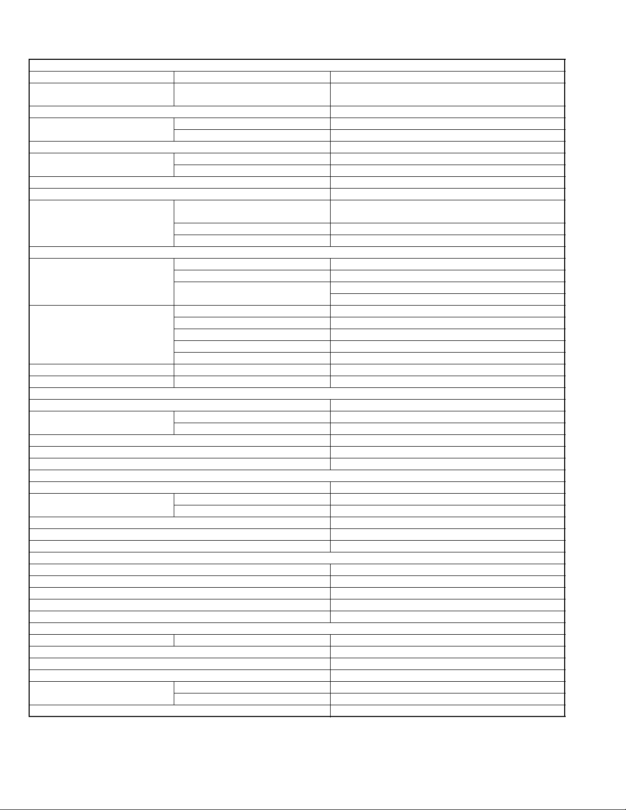
KW-AVX720EE
AMPLIFIER
Maximum Power Output Front/Rear 50 W per channel
Continuous Power Output (RMS) Front/Rear 20 W per channel into 4 Ω, 40 Hz to 20 000 Hz at no more
than 1.0% total harmonic distortion
Load Impedance 4 Ω (4 Ω to 8 Ω allowance)
Equalizer Control Range Frequencies 60 Hz, 150 Hz, 400 Hz, 1 kHz, 2.5 kHz, 6.3 kHz, 15 kHz
Level ±10 dB
Signal-to-Noise Ratio 70 dB
Audio Output Level
LINE OUT (REAR) and SUBWOOFER
Color System PAL
Video Output (composite) 1 Vp-p/75 Ω
Other Terminals Input LINE IN, VIDEO IN, Aerial input, USB input, Steering
Frequency Range FM1/FM2 87.5 MHz to 108.0 MHz
FM Tuner Usable Sensitivity 9.3 dBf (0.8 µV/75 Ω)
MW Tuner Sensitivity/Selectivity 20 µV/40 dB
LW Tuner Sensitivity 50 µV
Signal Detection System Non-contact optical pickup (semiconductor laser)
Frequency Response DVD, fs=48 kHz/96 kHz 16 Hz to 22 000 Hz
Dynamic Range 96 dB
Signal-to-Noise Ratio 98 dB
Wow and Flutter Less than measurable limit
USB Standards USB 2.0 Full Speed
Data Transfer Rat Full Speed Maximum 12 Mbps
Compatible Device Mass storage class
Compatible File System FAT 32/16/12
Max. Current DC 5 V 500 mA
Screen Size 7 inch wide liquid crystal display
Number of Pixel 336 960 pixels: 480 × 3 (horizontal) × 234 (vertical)
Drive Method TFT (Thin Film Transistor) active matrix format
Color System NTSC/PAL
Aspect Ratio 16:9 (wide)
Power Requirement Operating Voltage DC 14.4 V (11 V to 16 V allowance)
Grounding System Negative ground
Allowable Storage Temperature -10°C to +60°C
Allowable Operating Temperature 0°C to +40°C
Dimensions (W × H × D)
With trim plate and sleeve attached
Mass (approx.) 3.3 kg (including trim plate and sleeve)
Line-Out Level/Impedance 2.5 V/20 kΩ load (full scale)
Output Impedance 1 kΩ
wheel remote input
Output VIDEO OUT
Others CD changer, DIGITAL OUT (optical)
FM/AM TUNER
FM3 65.0 MHz to 74.0 MHz
AM (MW) 522 kHz to 1 620 kHz
(LW) 144 kHz to 279 kHz
50 dB Quieting Sensitivity 16.3 dBf (1.8 µV/75 Ω)
Alternate Channel Selectivity (400 kHz)
Frequency Response 40 Hz to 15 000 Hz
Stereo Separation 40 dB
DVD/CD
VCD/CD 16 Hz to 20 000 Hz
USB
Low Speed Maximum 1.5 Mbps
MONITOR
GENERAL
Installation Size (approx.) 182 mm × 111 mm × 161 mm
Panel Size (approx.) 188 mm × 117 mm × 22 mm
65 dB
Design and specifications are subject to change without notice.
1-4 (No.MA443<Rev.001>)
KW-AVX726/KW-AVX725/KW-AVX626/KW-AVX625EU
AMPLIFIER
Maximum Power Output Front/Rear 50 W per channel
Continuous Power Output (RMS) Front/Rear 20 W per channel into 4 Ω, 40 Hz to 20 000 Hz at no more
than 1.0% total harmonic distortion
Load Impedance 4 Ω (4 Ω to 8 Ω allowance)
Equalizer Control Range Frequencies 60 Hz, 150 Hz, 400 Hz, 1 kHz, 2.5 kHz, 6.3 kHz, 15 kHz
Level ±10 dB
Signal-to-Noise Ratio 70 dB
Audio Output LevelLINE OUT (REAR) and
SUBWOOFER (for KW-AVX726/KW-AVX725)
Color System KW-AVX726/KW-AVX725 NTSC/PAL
Video Output (composite) 1 Vp-p/75 Ω
Other Terminals Input LINE IN, VIDEO IN, Aerial input
Frequency Range FM 87.5 MHz to 108.0 MHz
FM Tuner Usable Sensitivity 9.3 dBf (0.8 µV/75 Ω)
AM/MW Tuner Sensitivity/Selectivity 20 µV/40 dB
LW Tuner Sensitivity 50 µV
Signal Detection System Non-contact optical pickup (semiconductor laser)
Frequency Response DVD, fs=48 kHz/96 kHz 16 Hz to 22 000 Hz
Dynamic Range 96 dB
Signal-to-Noise Ratio 98 dB
Wow and Flutter Less than measurable limit
USB Standards USB 2.0 Full Speed
Data Transfer Rat Full Speed Maximum 12 Mbps
Compatible Device Mass storage class
Compatible File System FAT 32/16/12
Max. Current DC 5 V 500 mA
Screen Size 7 inch wide liquid crystal display
Number of Pixel 336 960 pixels: 480 × 3 (horizontal) × 234 (vertical)
Drive Method TFT (Thin Film Transistor) active matrix format
Color System NTSC/PAL
Aspect Ratio 16:9 (wide)
Power Requirement Operating Voltage DC 14.4 V (11 V to 16 V allowance)
Grounding System Negative ground
Allowable Storage Temperature -10°C to +60°C
Allowable Operating Temperature 0°C to +40°C
Dimensions (W × H × D)
With trim plate and sleeve attached
Mass (approx.) 3.3 kg (including trim plate and sleeve)
Line-Out Level/Impedance 2.5 V/20 kΩ load (full scale)
Output Impedance 1 kΩ
KW-AVX626/KW-AVX625 PAL
USB input (for KW-AVX726/KW-AVX725)
Output VIDEO OUT
Others CD changer, DIGITAL OUT (optical), POSITION OUT
FM/AM TUNER
AM KW-AVX726/KW-AVX725 (MW) 522 kHz to 1 620 kHz
(LW) 144 kHz to 279 kHz
KW-AVX626/KW-AVX625 531 kHz to 1 602 kHz
50 dB Quieting Sensitivity 16.3 dBf (1.8 µV/75 Ω)
Alternate Channel Selectivity (400 kHz) 65 dB
Frequency Response 40 Hz to 15 000 Hz
Stereo Separation 40 dB
DVD/CD
VCD/CD 16 Hz to 20 000 Hz
USB (for KW-AVX726/KW AVX725)
Low Speed Maximum 1.5 Mbps
MONITOR
GENERAL
Installation Size (approx.) 182 mm × 111 mm × 161 mm
Panel Size (approx.) 188 mm × 117 mm × 22 mm
Design and specifications are subject to change without notice.
(No.MA443<Rev.001>)1-5
KW-AVX726/KW-AVX725/KW-AVX724/KW-AVX626/KW-AVX625/KW-AVX624 U/UN/UT/A/UI
AMPLIFIER
Maximum Power Output Front/Rear 50 W per channel
Continuous Power Output (RMS) Front/Rear 20 W per channel into 4 Ω, 40 Hz to 20 000 Hz at no more
than 1.0% total harmonic distortion
Load Impedance 4 Ω (4 Ω to 8 Ω allowance)
Equalizer Control Range Frequencies 60 Hz, 150 Hz, 400 Hz, 1 kHz, 2.5 kHz, 6.3 kHz, 15 kHz
Level ±10 dB
Signal-to-Noise Ratio 70 dB
Audio Output Level LINE OUT (REAR) and SUBWOOFER
(for KW-AVX726/KW-AVX725/KW-AVX724)
Color System NTSC/PAL
Video Output (composite) 1 Vp-p/75 Ω
Other Terminals Input LINE IN, VIDEO IN, Antenna input
Frequency Range FM 87.5 MHz to 108.0 MHz
FM Tuner Usable Sensitivity 9.3 dBf (0.8 µV/75 Ω)
AM Tuner Sensitivity/Selectivity 20 µV/40 dB
Signal Detection System Non-contact optical pickup (semiconductor laser)
Frequency Response DVD, fs=48 kHz/96 kHz 16 Hz to 22 000 Hz
Dynamic Range 96 dB
Signal-to-Noise Ratio 98 dB
Wow and Flutter Less than measurable limit
USB Standards USB 2.0 Full Speed
Data Transfer Rate Full Speed Maximum 12 Mbps
Compatible Device Mass storage class
Compatible File System FAT 32/16/12
Max. Current DC 5 V 500 mA
Screen Size 7 inch wide liquid crystal display
Number of Pixel 336 960 pixels: 480 × 3 (horizontal) × 234 (vertical)
Drive Method TFT (Thin Film Transistor) active matrix format
Color System NTSC/PAL
Aspect Ratio 16:9 (wide)
Power Requirement Operating Voltage DC 14.4 V (11 V to 16 V allowance)
Grounding System Negative ground
Allowable Storage Temperature -10°C to +60°C
Allowable Operating Temperature 0°C to +40°C
Dimensions (W × H × D) Installation Size (approx.) 178 mm × 100 mm × 160 mm
Mass (approx.) 2.7 kg
Line-Out Level/Impedance 2.5 V/20 kΩ load (full scale)
Output Impedance 1 kΩ
USB input (for KW-AVX726/KW-AVX725/KW-AVX724)
Output VIDEO OUT
Others CD changer, DIGITAL OUT (optical), POSITION OUT
FM/AM TUNER
AM 531 kHz to 1 602 kHz
50 dB Quieting Sensitivity 16.3 dBf (1.8 µV/75 Ω)
Alternate Channel Selectivity (400 kHz)
Frequency Response 40 Hz to 15 000 Hz
Stereo Separation 40 dB
DVD/CD
VCD/CD 16 Hz to 22 000 Hz
USB (for KW-AVX726/KW-AVX725/KW-AVX724)
Low Speed Maximum 1.5 Mbps
MONITOR
GENERAL
Panel Size (approx.) 184 mm × 112 mm × 23 mm
65 dB
Design and specifications are subject to change without notice.
1-6 (No.MA443<Rev.001>)
SECTION 1
PRECAUTION
1.1 Safety Precautions
(1) This design of this product contains special hardware and
many circuits and components specially for safety purposes. For continued protection, no changes should be made
to the original design unless authorized in writing by the
manufacturer. Replacement parts must be identical to
those used in the original circuits. Services should be performed by qualified personnel only.
(2) Alterations of the design or circuitry of the product should
not be made. Any design alterations of the product should
not be made. Any design alterations or additions will void
the manufacturers warranty and will further relieve the
manufacture of responsibility for personal injury or property
damage resulting therefrom.
(3) Many electrical and mechanical parts in the products have
special safety-related characteristics. These characteristics are often not evident from visual inspection nor can the
protection afforded by them necessarily be obtained by using replacement components rated for higher voltage, wattage, etc. Replacement parts which have these special
safety characteristics are identified in the Parts List of Service Manual. Electrical components having such features
are identified by shading on the schematics and by ( ) on
the Parts List in the Service Manual. The use of a substitute
replacement which does not have the same safety characteristics as the recommended replacement parts shown in
the Parts List of Service Manual may create shock, fire, or
other hazards.
(4) The leads in the products are routed and dressed with ties,
clamps, tubings, barriers and the like to be separated from
live parts, high temperature parts, moving parts and/or
sharp edges for the prevention of electric shock and fire
hazard. When service is required, the original lead routing
and dress should be observed, and it should be confirmed
that they have been returned to normal, after reassembling.
(5) Leakage shock hazard testing
After reassembling the product, always perform an isolation check on the exposed metal parts of the product (antenna terminals, knobs, metal cabinet, screw heads,
headphone jack, control shafts, etc.) to be sure the product
is safe to operate without danger of electrical shock.Do not
use a line isolation transformer during this check.
• Plug the AC line cord directly into the AC outlet. Using a
"Leakage Current Tester", measure the leakage current
from each exposed metal parts of the cabinet, particularly any exposed metal part having a return path to the
chassis, to a known good earth ground. Any leakage current must not exceed 0.5mA AC (r.m.s.).
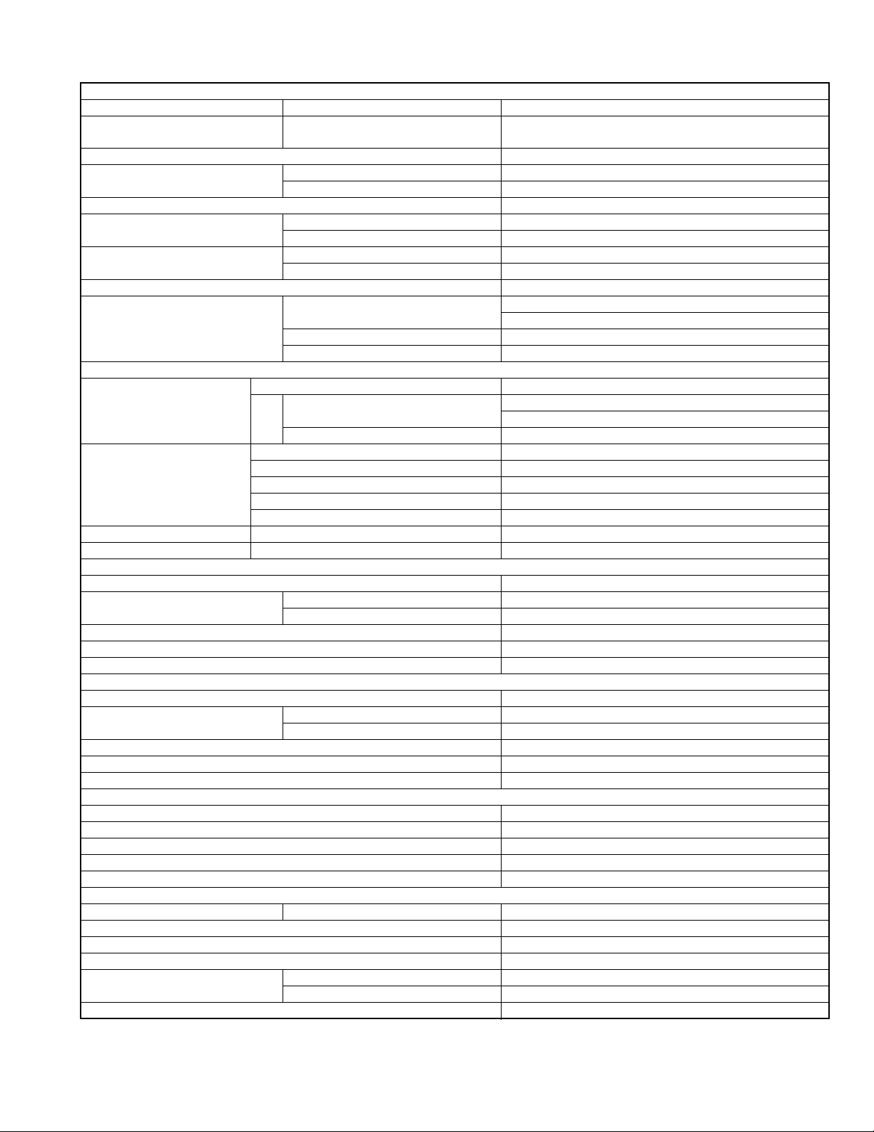
• Alternate check method
Plug the AC line cord directly into the AC outlet. Use an
AC voltmeter having, 1,000
in the following manner. Connect a 1,500
paralleled by a 0.15
exposed metal part and a known good earth ground.
Measure the AC voltage across the resistor with the AC
Ω per volt or more sensitivity
Ω 10W resistor
µF AC-type capacitor between an
voltmeter.
Move the resistor connection to each exposed metal
part, particularly any exposed metal part having a return
path to the chassis, and measure the AC voltage across
the resistor. Now, reverse the plug in the AC outlet and
repeat each measurement. Voltage measured any must
not exceed 0.75 V AC (r.m.s.). This corresponds to 0.5
mA AC (r.m.s.).
AC VOLTMETER
(Having 1000
ohms/volts,
or more sensitivity)
0.15 F AC TYPE
Place this
probe on
1500 10W
Good earth ground
1.2 Warning
(1) This equipment has been designed and manufactured to
meet international safety standards.
(2) It is the legal responsibility of the repairer to ensure that
these safety standards are maintained.
(3) Repairs must be made in accordance with the relevant
safety standards.
(4) It is essential that safety critical components are replaced
by approved parts.
(5) If mains voltage selector is provided, check setting for local
voltage.
1.3 Caution
Burrs formed during molding may be left over on some parts
of the chassis.
Therefore, pay attention to such burrs in the case of preforming repair of this system.
1.4 Critical parts for safety
In regard with component parts appearing on the silk-screen
printed side (parts side) of the PWB diagrams, the parts that are
printed over with black such as the resistor ( ), diode ( )
and ICP ( ) or identified by the " " mark nearby are critical
for safety. When replacing them, be sure to use the parts of the
same type and rating as specified by the manufacturer.
(This regulation dose not Except the J and C version)
each exposed
metal part.
(No.MA443<Rev.001>)1-7
1.5 Preventing static electricity
Electrostatic discharge (ESD), which occurs when static electricity stored in the body, fabric, etc. is discharged, can destroy the laser
diode in the traverse unit (optical pickup). Take care to prevent this when performing repairs.
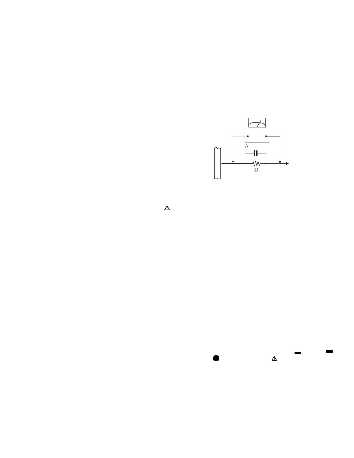
1.5.1 Grounding to prevent damage by static electricity
Static electricity in the work area can destroy the optical pickup (laser diode) in devices such as laser products.
Be careful to use proper grounding in the area where repairs are being performed.
(1) Ground the workbench
Ground the workbench by laying conductive material (such as a conductive sheet) or an iron plate over it before placing the
traverse unit (optical pickup) on it.
(2) Ground yourself
Use an anti-static wrist strap to release any static electricity built up in your body.
(caption)
Anti-static wrist strap
1M
Conductive material
(conductive sheet) or iron palate
(3) Handling the optical pickup
• In order to maintain quality during transport and before installation, both sides of the laser diode on the replacement optical
pickup are shorted. After replacement, return the shorted parts to their original condition.
(Refer to the text.)
• Do not use a tester to check the condition of the laser diode in the optical pickup. The tester's internal power source can easily
destroy the laser diode.
1.6 Handling the traverse unit (optical pickup)
(1) Do not subject the traverse unit (optical pickup) to strong shocks, as it is a sensitive, complex unit.
(2) Cut off the shorted part of the flexible cable using nippers, etc. after replacing the optical pickup. For specific details, refer to the
replacement procedure in the text. Remove the anti-static pin when replacing the traverse unit. Be careful not to take too long a
time when attaching it to the connector.
(3) Handle the flexible cable carefully as it may break when subjected to strong force.
(4) I t is not possible to adjust the semi-fixed resistor that adjusts the laser power. Do not turn it.
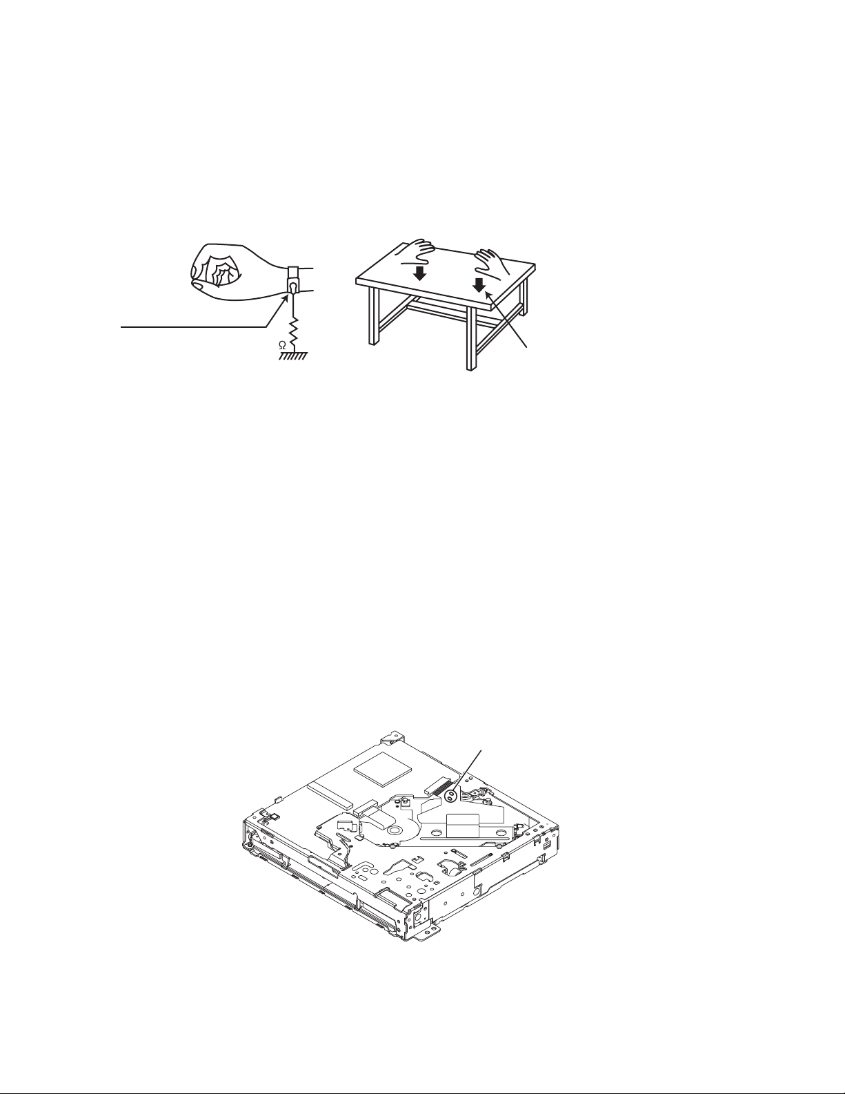
1.7 Attention when traverse unit is decomposed
*Please refer to "Disassembly method" in the text for the pickup unit.
• Apply solder to the short land sections before the card wire is disconnected from the connecto on the servo board. (If the card wire
is disconnected without applying solder, the pickup may be destroyed by static electricity.)
• In the assembly, be sure to remove solder from the short land sections after connecting the card wire.
Solder short part
1-8 (No.MA443<Rev.001>)
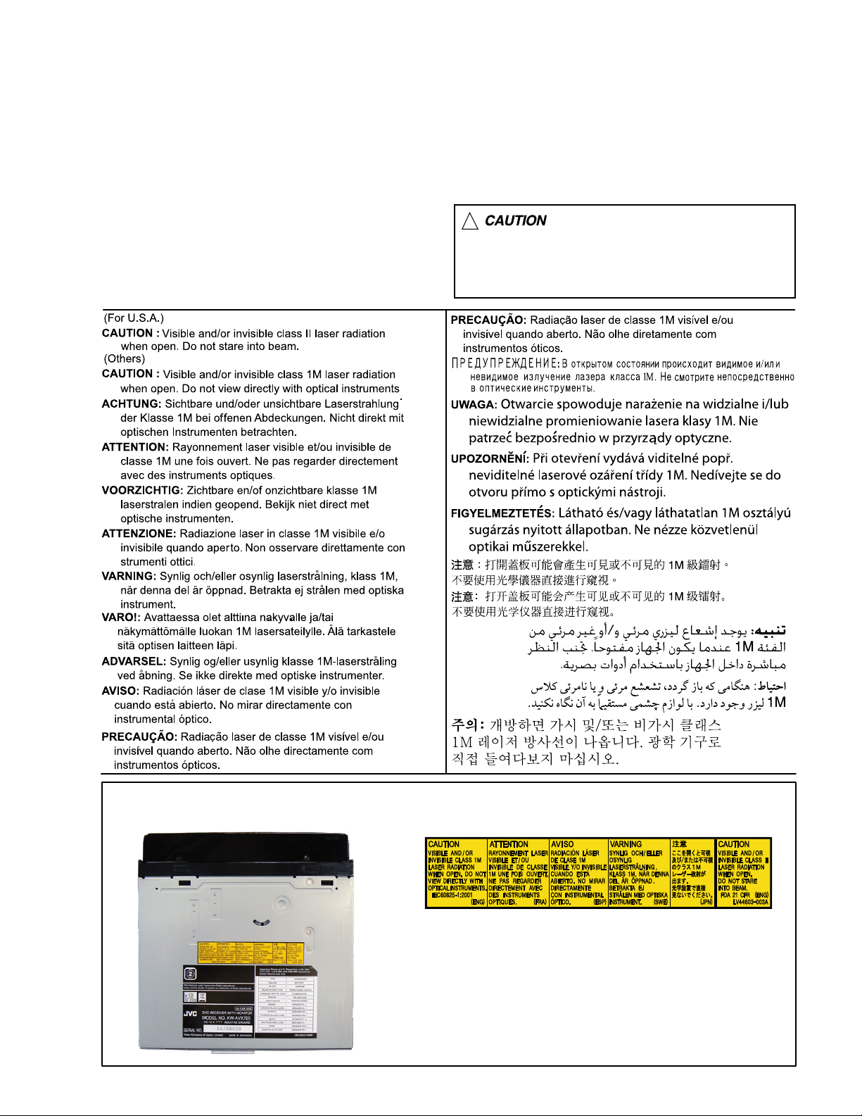
1.8 Important for laser products
1.CLASS 1 LASER PRODUCT
2.CAUTION :
(For U.S.A.) Visible and/or invisible class II laser radiation
when open. Do not stare into beam.
(Others) Visible and/or invisible class 1M laser radiation
when open. Do not view directly with optical instruments.
3.CAUTION : Visible and/or invisible laser radiation when
open and inter lock failed or defeated. Avoid direct
exposure to beam.
4.CAUTION : This laser product uses visible and/or invisible
laser radiation and is equipped with safety switches which
prevent emission of radiation when the drawer is open and
the safety interlocks have failed or are defeated. It is
dangerous to defeat the safety switches.
5.CAUTION : If safety switches malfunction, the laser is able
to function.
6.CAUTION : Use of controls, adjustments or performance of
procedures other than those specified here in may result in
hazardous radiation exposure.
!
Please use enough caution not to
see the beam directly or touch it
in case of an adjustment or operation
check.
REPRODUCTION AND POSITION OF LABELS and PRINT
WARNING LABEL and PRINT
(No.MA443<Rev.001>)1-9
SECTION 2
SPECIFIC SERVICE INSTRUCTIONS
This service manual does not describe SPECIFIC SERVICE INSTRUCTIONS.
SECTION 3
DISASSEMBLY
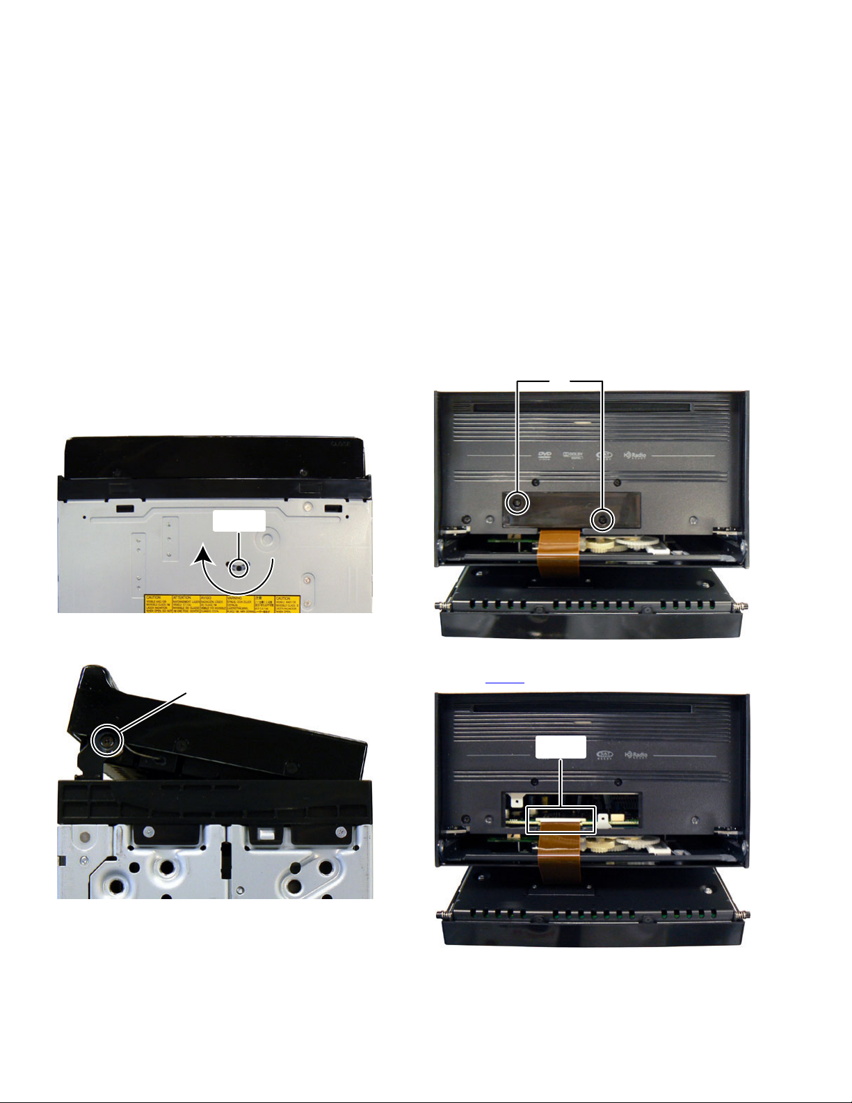
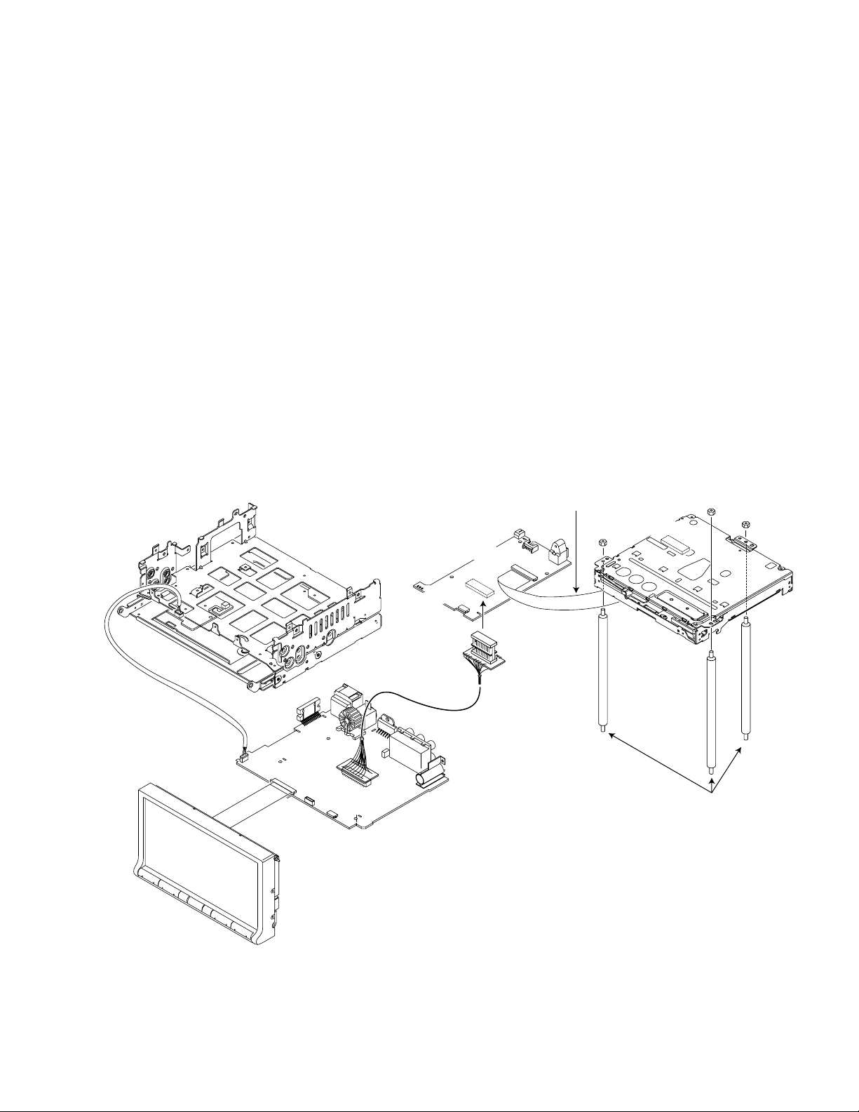
3.1 Main body (Used figure are KW-AVX720J)
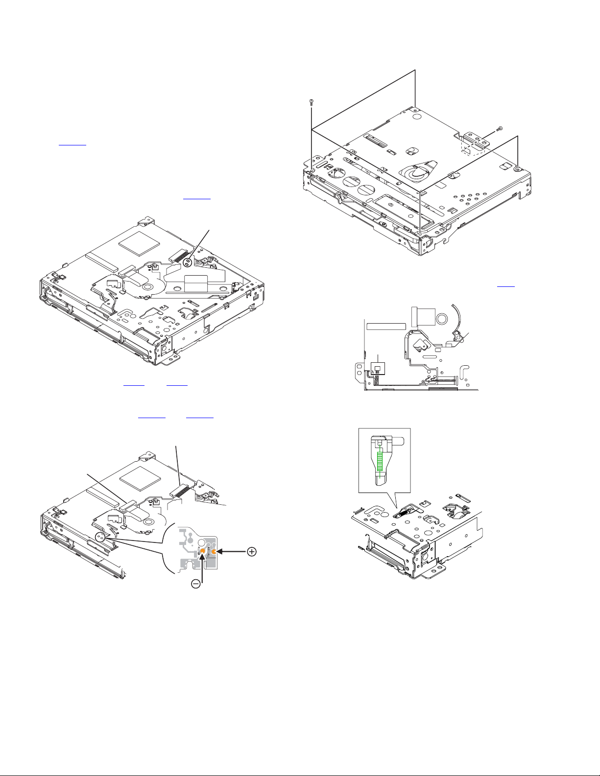
3.1.1 Removing the Front panel (See Fig.1 to 4)
(1) From the bottom side of the main body, insert the screw-
driver to hole of the third gear from hole a of the bottom
chassis, and then turn the gear to clockwise until Front
panel comes up. (See Fig.1)
hole a
Fig.1
(2) Remove the two screws A attaching the both side of the
Front panel. (See Fig.2)
A
(3) Remove the two screws B attaching the FPC cover. (See
Fig.3)
B
Fig.3
(4) Disconnect the FPC from Front panel connected to con-
nector CN701
of the Main board. (See Fig.4)
1-10 (No.MA443<Rev.001>)
CN701
Fig.2
Fig.4
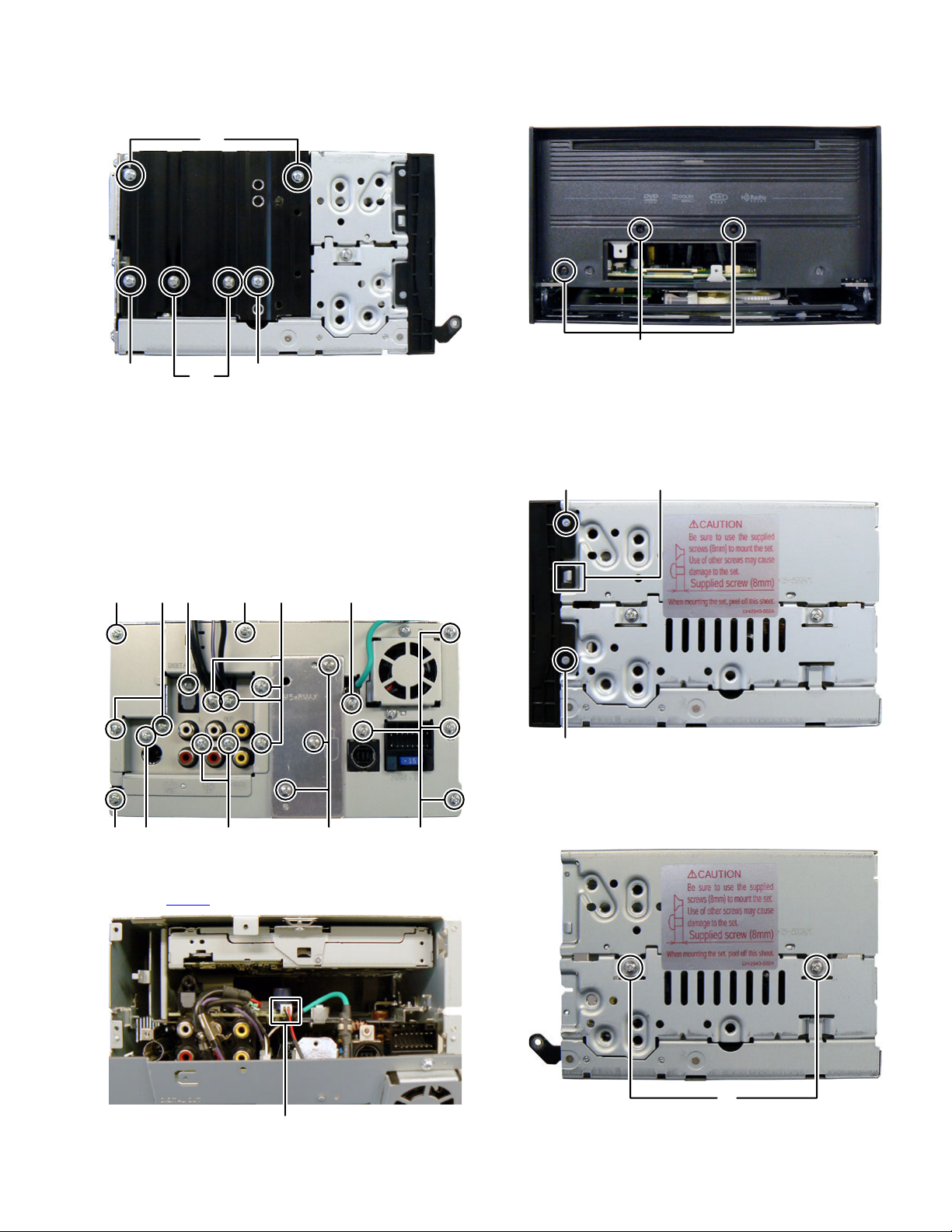
3.1.2 Removing the Heat sink (See Fig.5)
(1) Remove the four screws C and two screws D attaching the
Heat sink.
C
CDC
Fig.5
3.1.3 Removing the Rear bracket (A) (See Fig.6, 7)
(1) Remove the three screws E attaching the Rear heat sink.
(See Fig.6)
(2) Remove the six screws F, two screws G, one screw H and
one screw J attaching the Rear bracket (B). (See Fig.6)
(3) Remove the one screw K attaching the Subwoofer cable.
(See Fig.6)
(4) Remove the seven screws L attaching the Rear bracket
(A). (See Fig.6)
3.1.4 Removing the Front chassis (See Fig.8, 9)
(1) Remove the three screws M attaching the Front chassis.
(See Fig.8)
M
Fig.8
(2) Remove the four screws N attaching the both side of the
Front chassis. (See Fig.9)
(3) Disengage two hooks b engaged both side of the Front
chassis. (See Fig.9)
hook
N
b
FKLFJ
EGHLL
Fig.6
(5) Disconnect the connector wire from FAN connected to con-
nector CN604
of the Sub board. (See Fig.7)
N
Fig.9
3.1.5 Removing the Top chassis (See Fig.10, 11)
(1) Remove the two screws P attaching the Top chassis. (See
Fig.10)
CN604
Fig.7
P
Fig.10
(No.MA443<Rev.001>)1-11
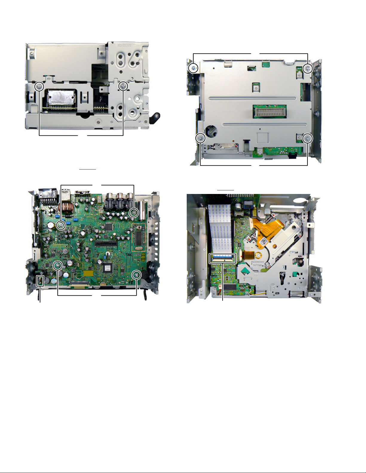
(2) Remove the two screws Q attaching the Top chassis. (See
Fig.11)
Q
Fig.11
3.1.6 Removing the Main board (See Fig.12)
(1) Disconnect the connector wire from Door switch board con-
nected to connector CN961
(2) Remove the four screws R attaching the Main board.
of the Main board.
R
3.1.7 Removing the DVD mechanism (See Fig.13 to 16)
(1) Remove the four screws S attaching the Sub board brack-
et. (See Fig.13)
S
S
Fig.13
(2) Disconnect the card wire from Sub board connected to
connector CN403
of the Front end board. (See Fig.14)
CN961
1-12 (No.MA443<Rev.001>)
R
Fig.12
CN403
Fig.14
(3) Remove the three screws T attaching the Support bracket.
(See Fig.15)
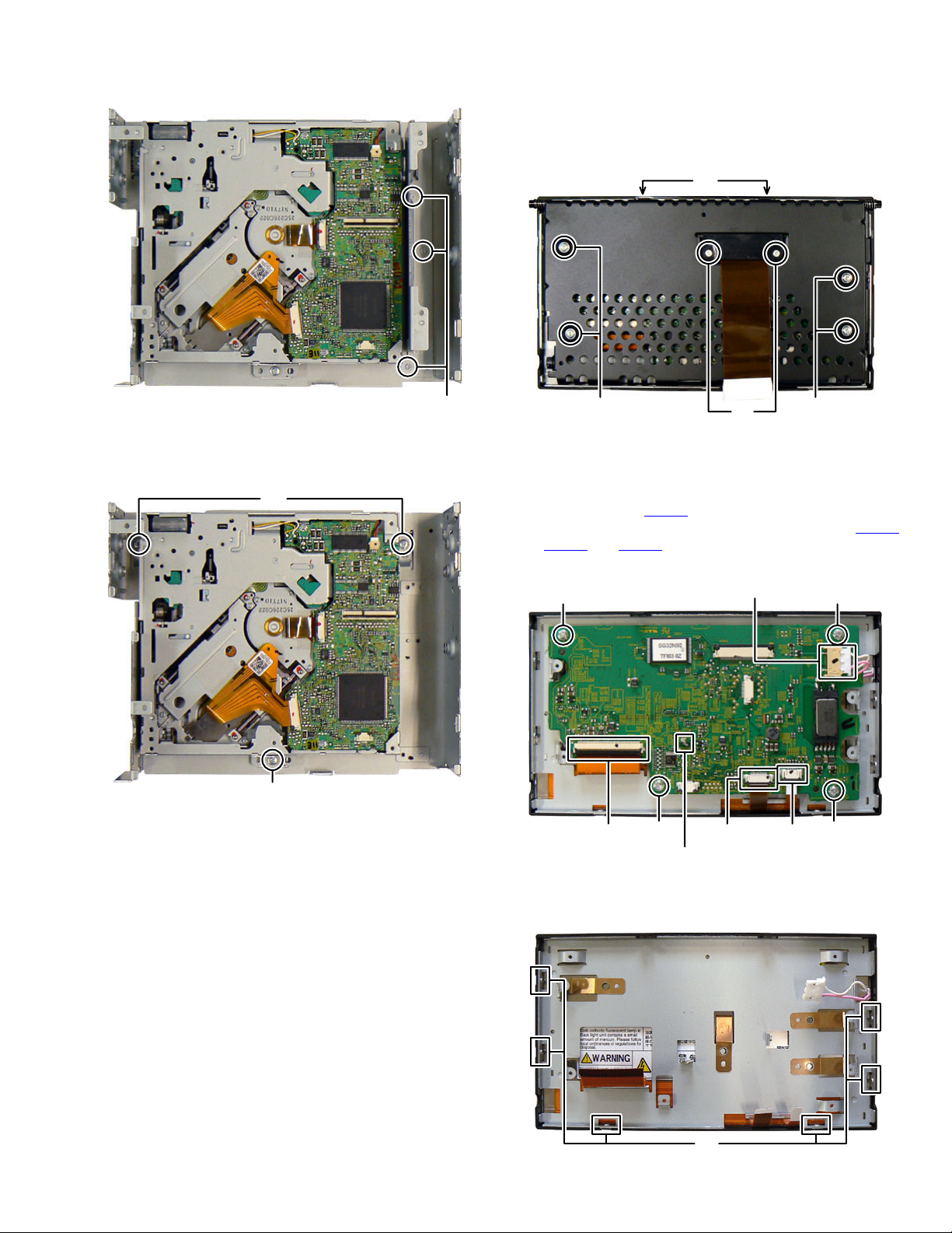
3.2 Monitor section
3.2.1 Removing the Front bracket (See Fig.1)
(1) Remove the two screws A attaching the FPC cover.
(2) Remove the four screws B attaching the Front bracket.
(3) Remove the two screws C attaching the Front bracket.
C
T
Fig.15
(4) Remove the three screws U attaching the DVD mecha-
nism. (See Fig.16)
U
U
Fig.16
ABB
Fig.1
3.2.2 Removing the Panel board (See Fig.2)
(1) Remove solder of hook a and straighten it.
(2) Disconnect the connector wire from LCD module connect-
ed to connector CN607
(3) Disconnect the FPC connected to connector CN601
CN602
and CN606 of the Panel board.
(4) Remove the four screws D attaching the Panel board.
DD
3.2.3 Removing the LCD module (See Fig.3)
(1) Remove the six screws E attaching the Panel bracket.
of the Panel board.
CN607
hook
CN601 CN602CN606
a
Fig.2
DD
,
E
Fig.3
(No.MA443<Rev.001>)1-13
3.3 DVD mechanism assembly section
3.3.1 Removing the Traverse mechanism assembly (See
Fig.1 to 6)
(1) Solder the short land section on the flexible wire of pickup.
(See Fig.1)
Caution:
* Solder the short land section on the flexible wire of pickup
before disconnecting the flexible wire form the connector
on the Front end board.
CN101
If the flexible wire is disconnected without attaching the
solder, the pickup may be destroyed by static electricity.
* When attaching the Traverse mechanism assembly, remove the solder from the short land section after connection
the flexible wire to the connector CN101
on the Front end
board.
Solder short part
(4) Remove the five screws A attaching the Top cover assembly.
(See Fig.3)
A
Fig.3
(5) From the bottom side, disconnect the connector wire from
Top cover assembly connected to connector CN2
Front end board. (See Fig.4)
of the
Fig.1
(2) Voltage supply to TP79
and TP81 approx DC 3.0V until
Clamper is shift to loading complete position. (See Fig.2)
(3) Disconnect the flexible wires from Traverse mechanism assembly
connected to connector CN101
and CN164 of the Front end
board. (See Fig.2)
CN101
CN164
TP79 TP81
TP79
R317
TP67
R312
R21
R357
TP81
TP92
CENTER
D-
DGND_7
WOOFER
Voltage supply
position
Fig.2
CN2
Fig.4
(6) From the bottom side, remove the spring from Traverse
mechanism assembly. (See Fig.5)
Fig.5
1-14 (No.MA443<Rev.001>)
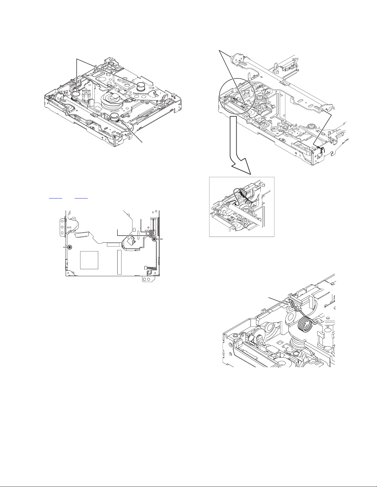
(7) From the top side, pull up the traverse mechanism and disengage
three dumper positions. (See Fig.6)
Dumper
(same color spring)
Dumper
(Different color spring)
Fig.6
3.3.2 Removing the Front end board (See Fig.7)
(1) Remove the Motor wires from loading motor soldered to
and TP81 of the Front end board.
TP79
(2) Remove the two screws B attaching the Front end board.
3.3.3 Removing the Loading arm assembly (See Fig.8)
(1) Remove the Loading arm spring L from Loading arm assembly.
(2) Slide to left side and then disengage hook a then hook b.
hook b
Loading arm
assembly
hook
Loading arm spring L
a
B
TP79
Fig.7
TP81
B
Fig.8
3.3.4 Removing the Gear base assembly (See Fig.9, 10)
(1) Remove the Loading arm spring L. (See Fig.9)
Loading arm
spring L
Fig.9
(No.MA443<Rev.001>)1-15
(2) Remove the two screws C attaching the Gear base assembly.
r
(See Fig.10)
C
Fig.10
3.3.5 Removing the Loading arm holder. (See Fig.11)
(1) Remove the two screws D attaching the Loading arm holder.
(2) Remove the Loading arm spring R.
D
Loading arm
holder
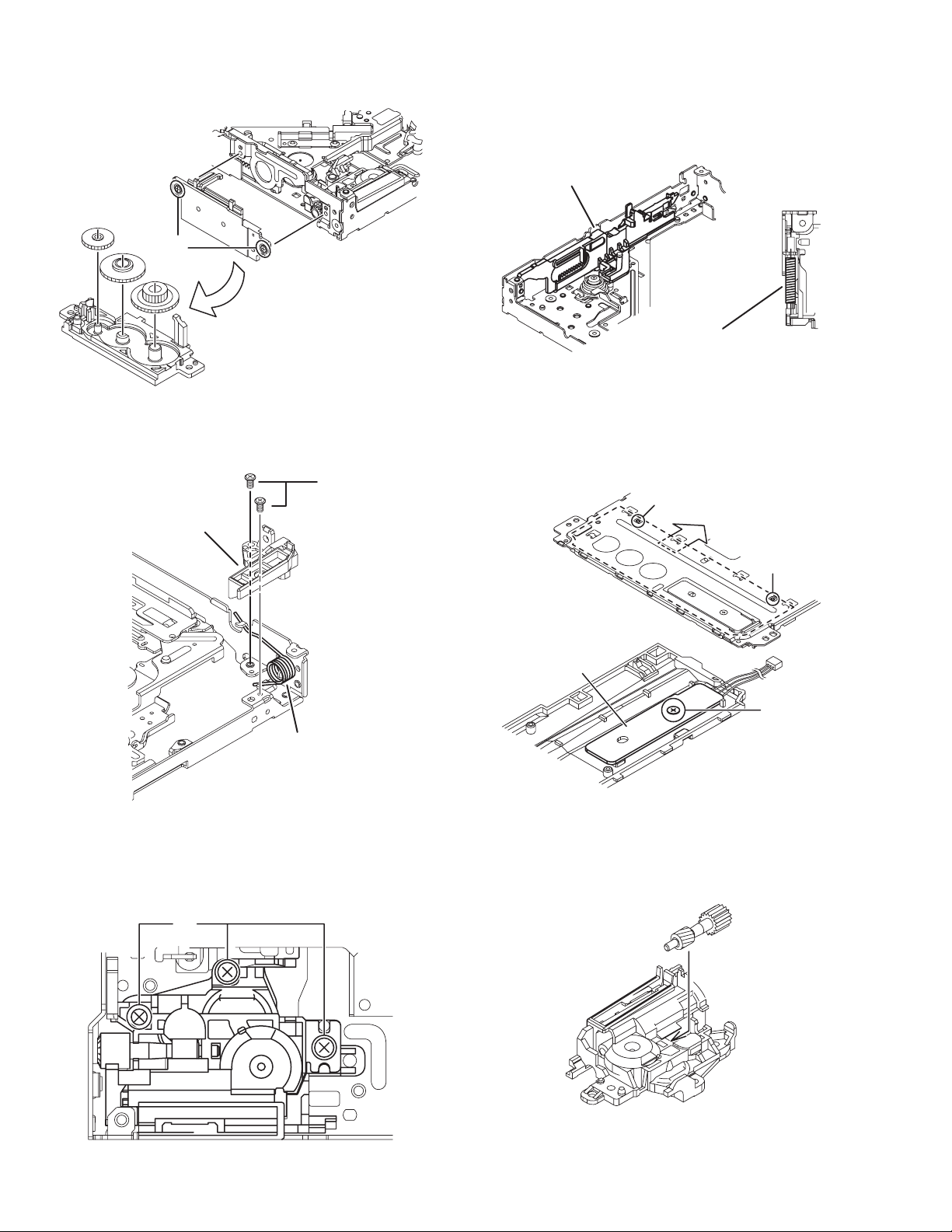
3.3.7 Removing the Slide cam assembly (See Fig.13)
(1) Slide to backward the Slide cam assembly and the remove
the Slide cam spring.
(2) Slide to frontward the slide cam assembly, and then take
out it.
Slide cam assembly
Slide cam spring
Fig.13
3.3.8 Removing the Photo board (See Fig.14)
(1) Pressing the hook c and then slide to backward (slide to the
arrow side) the Disc plate.
(2) Remove the one screw F attaching the Photo board.
hook
c
Loading arm
spring R
Fig.11
3.3.6 Removing the Loading moor assembly (See Fig.12)
(1) Remove the three screws E attaching the Loading motor
assembly.
E
hook
c
Photo board
F
Fig.14
3.3.9 Removing the Loading motor (See Fig.15 to 18)
(1) Remove the A wheel gear. (See Fig.15)
A Wheel gea
1-16 (No.MA443<Rev.001>)
Fig.15
Fig.12

(2) Remove the A worm gear, M connect gear and M wheel
gear by sequentially. (See Fig.16)
A worm gear
M connect gear
M wheel gear
Fig.16
(3) Remove the two screws G attaching the Loading motor.
(Se Fig.17)
G
Fig.17
(4) When attaching the Loading motor, motor wire should arrange
to figure. (See Fig.18)
Direction
R middle gear
R collar R
R connect gear
Slit washer
part c
part a
part b
Fig.19
3.3.11 Removing the Roller (See Fig.20)
(1) Remove the Slit washer.
(2) Pull out the Roller shaft.
CAUTION:
When reattach the Roller shaft, Slit washer should be change
new part.
Wire arrangement
Fig.18
3.3.10 Removing the Roller assembly (See Fig.19)
(1) Remove the Slit washer.
(2) Remove the R middle gear.
(3) Remove the R connect gear.
(4) Snap off the part a of the Roller assembly.
(5) Lift up the part b of the Roller assembly, and then release
part c (When release part c, R collar R is easy to come off,
does not lose it).
CAUTION:
When reattach the Roller assembly, Middle gear should keep
direction and Slit washer should be change new part.
slit
keep direction
keep direction
slit
small side
Fig.20
(No.MA443<Rev.001>)1-17

1-18 (No.MA443<Rev.001>)
SECTION 4
ADJUSTMENT
4.1 Test instruments required for adjustment
(1) Digital oscilloscope (100MHz)
(2) Digital tester
(3) Test Disc
(4) Extension cable : EXTXD001-50PF
EXTDV002-30P
EXTCN001-6P
(5) Extension stud : STDV001-3P
4.2 Standard measuring conditions
Power supply voltage DC14.4V(10.5 to 16V)
Load impedance 20K ohm (2 Speakers connection)
Output Level Line out 2.5V (Vol. MAX)
4.5 How to connect the extension cable for adjusting
Caution:
Be sure to attach the heat sink and rear bracket onto the power amplifier IC and regulator IC respectively, before supply the power.
If voltage is applied without attaching these parts, the power amplifier IC and regulator IC will be destroyed by heat.
4.3 Standard volume position
Balance and Bass &Treble volume : lndication"0"
Loudness : OFF
4.4 Dummy load
Exclusive dummy load should be used for AM,and FM.
For FM dummy load, there is a loss of 6dB between SSG output and antenna input.
The loss of 6dB need not be considered sincedirect reading of
figures are applied in this working standard.
EXTXD001-50PF
CN403
CN851
EXTCN001-6P
CN961
CN701
Original
cable
CN704
CN803
CN811
EXTDV002-30P
STDV001-3P
(No.MA443<Rev.001>)1-19
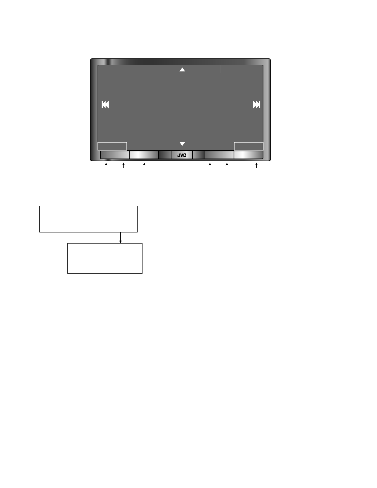
4.6 Service mode
4.6.1 Button position
UP Button
ENTER
REW Button FF Button
TOUCH PANEL
DOWN Button
[STANDBY/ON
[DISP] [VOL] [MENU TP/PTY] [SOURCE] [OPEN]
ATTENUATOR]
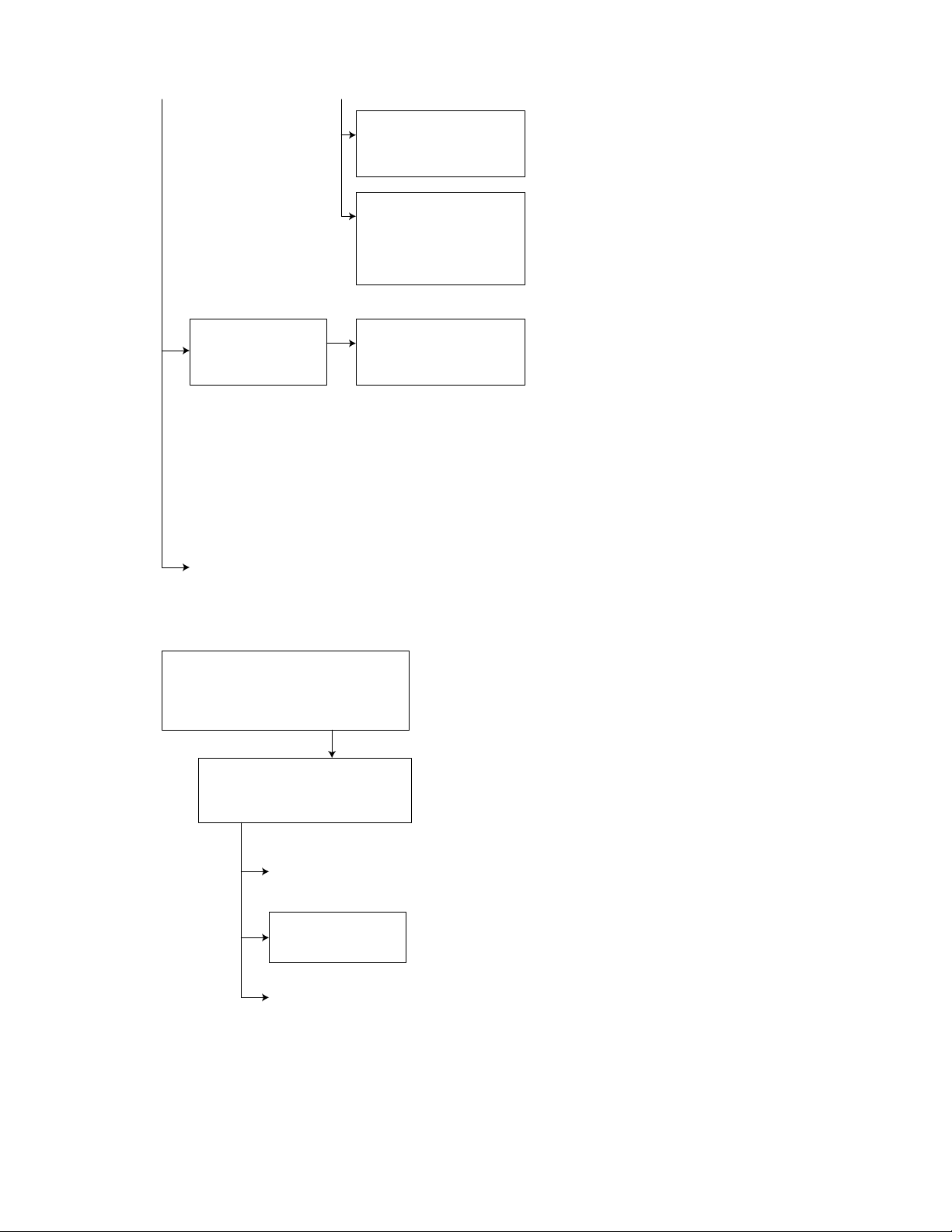
4.6.2 Service mode 1 (Indication of a service mode 1 is nothing.)
Keep this state more 2 seconds
while continuing pressing the
[STANDBY/ON ATTENUATOR] button
and [OPEN] button sequentially.
Screen indication
Exchanging it operate a menu of a service mode with the [UP] button
NO EJECT?
EMERGENCY EJECT?
and [DOWN] button. Operate choice of a menu with a [ENTER] button.
*1
*1 : When an [ENTER] button is pushed in NO EJECT indication, it is set
*2
by an EJECT prohibition mode.
When an [ENTER] button is pushed in EJECT OK indication, it is set
by a normal mode.
*2 : Forced EJECT movement
A screen becomes normal indication after an [ENTER] button was pushed.
[Exit][Back]
1-20 (No.MA443<Rev.001>)
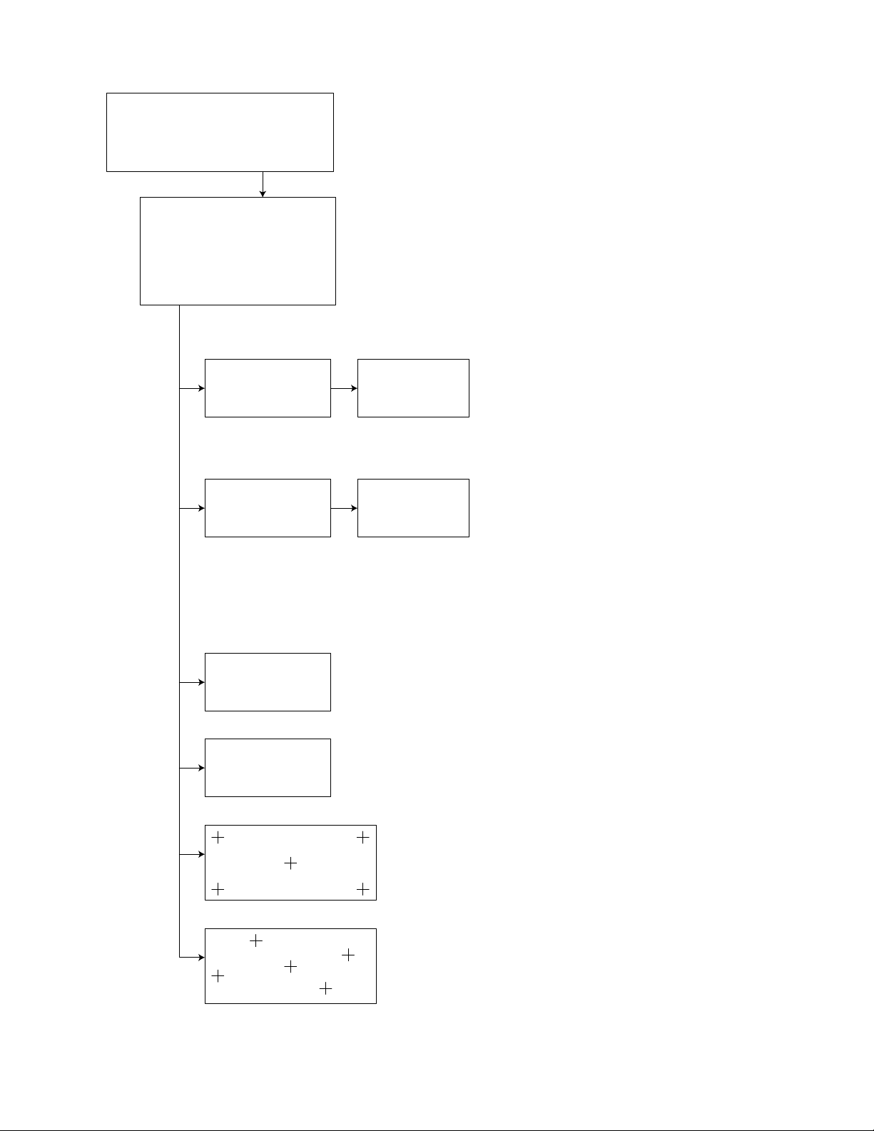
4.6.3 Service mode 2
Keep this state more 2 seconds
while continuing pressing the
[MENU or TP/PTY] button, [SOURCE]
button and TOUCH PANEL [DOWN]
button sequentially.
Screen indication
SERVICE MODE 2
INITIALIZE ALL
INITIALIZE
INITIALIZE DVD
INITIALIZE BT
TOUCH PANEL CALIBRATION
TOUCH PANEL CHECK MODE
Exchanging it operate a menu of a service mode with the [UP] button
and [DOWN] button. Operate choice of a menu with a [ENTER] button.
INITIALIZE ALL
...
NOW
INITIALIZE ALL
INITIALIZE
...
NOW
INITIALIZE
INITIALIZE DVD
INITIALIZE DVD
OK ***
INITIALIZE ALL
INITIALIZE ALL
OK **
INITIALIZE
OK **
Full initialization of EEPROM of a DVD unit ( It is included a permanent domain)
After clear completion, this indication is continued till an effective key is input.
(Each EEPROM is initialized by a factory shipment state.)
* Main micon EEPROM initialization (user entry domain,
error history, speaker setting, sub area of J-version,
data to pre-set )
* Panel micon EEPROM initialization
(picture adjustment data)
INITIALIZE (Initialization of a user area of each EEPROM)
* Main micon EEPROM initialization (a user entry domain )
(a user entry domain, speaker setting, sub area of
J-version, data to pre-set )
* Panel micon EEPROM initialization
(picture adjustment data )
* DVD unit EEPROM initialization
(except a permanent domain)
* Bluetooth (Module/Hideaway) EEPROM initialization
* After clear completion, a screen returns to normal indication
after OK indication was displayed for three seconds.
INITIALIZE BT
INITIALIZE BT
OK ***
TOUCH PANEL CALIBRATION
TOUCH PANEL CHECK MODE
Full initialization of EEPROM of Bluetooth ( Module/Hideaway )
After clear completion, this indication is continued till an effective key is input.
Push the center of a + character displayed in turn.
The confirmation mode that the calibration of the touch panel was
performed definitely.
*Return to previous menu with a [DISP] button.
(No.MA443<Rev.001>)1-21
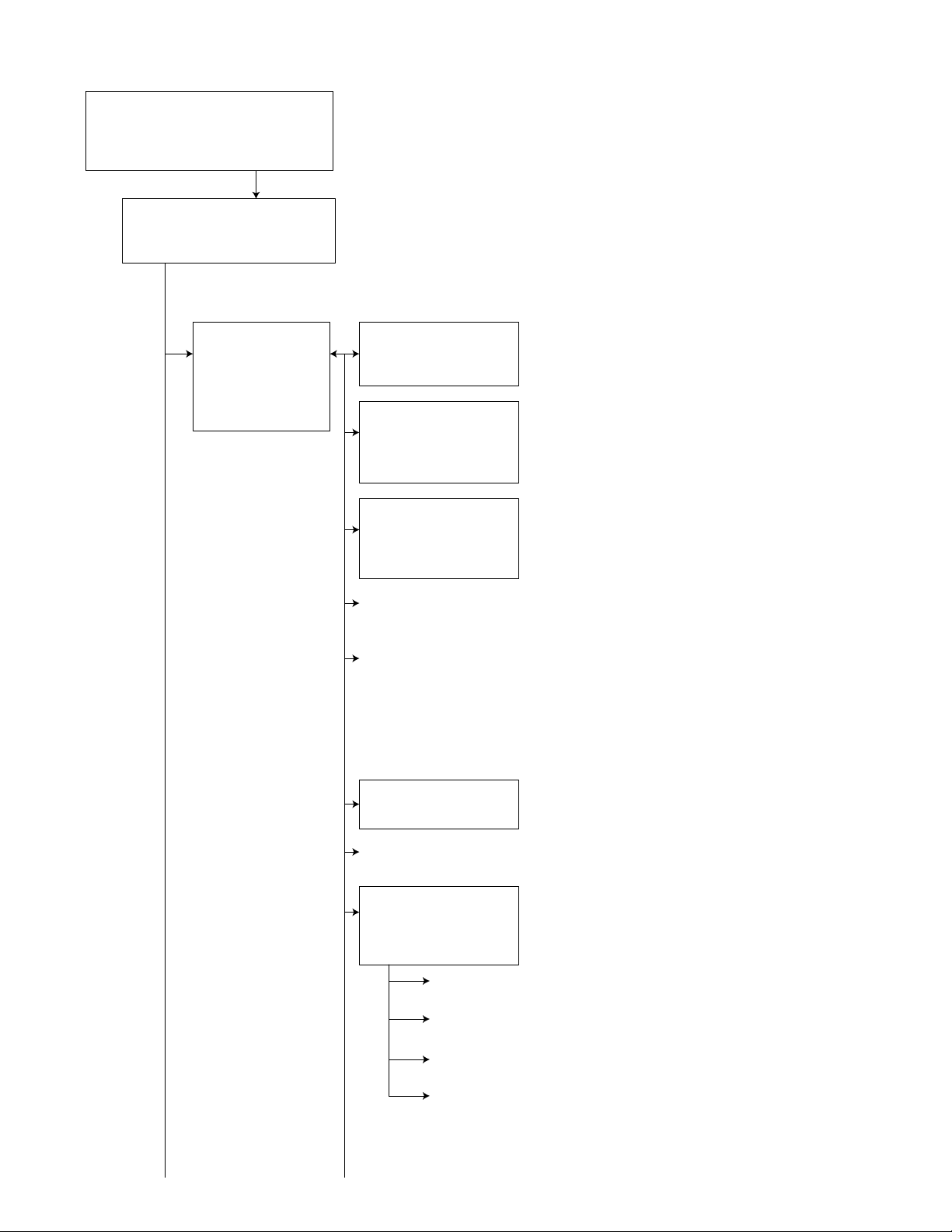
4.6.4 Service mode 3
Keep this state more 2 seconds
while continuing pressing the
[MENU or TP/PTY] button, [VOLUME -]
button and TOUCH PANEL [DOWN]
button sequentially.
Screen indication
SERVICE MODE 3
SERVICE MODE
INITIALIZE ALL
RUNNING MODE
Exchanging it operate a menu of a service mode with the [UP] button
and [DOWN] button. Operate choice of a menu with a [ENTER] button.
SERVICE MODE
SERVICE MODE
VERSION
AREA/REGION
TEMPERATURE
MEMORY CHECK
DVD NTSC/PAL
DVD CHECK MODE
* Exchanging it operate
a menu of a service
mode with the [UP]
button and [DOWN]
button.
* Operate choice of a
menu with a [ENTER]
button.
* Return to previous
menu with a [BACK]
button.
SERVICE MODE
ERROR READ
ERROR CLEAR
BT VERSION
VERSION
MAIN
DISC
CH
PA
AREA/REGION
SYS-AREA
DISC-AREA
REGION
PANEL-AREA
TEMPERATURE Temperature data reading
* Temperature data by the temperature sensor in the main micon
and DVD module is read every 5 seconds and displayed in hex numbers.
MEMORY CHECK ( It is displayed only at the time of the disc insertion )
Memory residual quantity indication mode
* Data residual quantity of a disc is displayed by LCD.
* About the playback control-related key ([FSKIP], [BSKIP],
[UP], [DOWN], [VOL]), only movement is effective.
Indication does not change as memory residual quantity indication.
* About cancellation of this mode, press the [STANDBY/ON ATTENUATOR]
button.
V**** [**]
****
******
V**** V*** [**]
Micon version indication
Main micon version and ROM correction version
DVD module version
CH version
Panel micon version and ROM correction version
Area and region indication
Main micon area
: **
DVD module area
: **
Region
: *
Panel area
: **
1-22 (No.MA443<Rev.001>)
DVD NTSC/PAL
NTSC
PAL
DVD CHECK MODE
* See "DVD CHECK MODE" for details.
ERROR READ
DVD ERROR READ
CH ERROR READ
MECHA ERROR READ
READ ALL
DVD ERROR READ
Reading of a DVD unit error history
CH ERROR READ
Reading of a CD changer error history
MECHA ERROR READ
Reading of a door mechanism error history
READ ALL
Reading of a main micon EEPROM (All contents)
DVD picture change
DVD unit output picture setting (NTSC)
DVD unit output picture setting (PAL)
ERROR CLEAR
DVD ERROR CLEAR
CH ERROR CLEAR
MECHA ERROR CLEAR
Clear of each error history
A screen returns to following
indication after clear completion.
INITIALIZE ALL
NOW
INITIALIZE ALL INITIALIZE ALL
RUNNING MODE
* See "Running mode" for details.
4.6.5 Service mode 4
BT VERSION
SW BT CORE
HW BT MODULE
SW BT MODULE
SW HIDEAWAY
ADR-
...
OK **
***
***
***
***
***********
Bluetooth version indication
Software version of BT core
Hardware version of BT Module
Software version of BT Module
Software version of BT Hideaway controller
BT Address
INITIALIZE ALL
(Each EEPROM is initialized by a factory
shipment state.)
* Main micon EEPROM initialization
(user entry domain, error history,speaker setting,
sub area of J-version, data to pre-set )
* Panel micon EEPROM initialization
(picture adjustment data)
* DVD unit EEPROM initialization
(except a permanent domain)
* Bluetooth (Module/Hideaway)
EEPROM initialization
* After clear completion, a screen returns to normal
indication after OK indication was
displayed for three seconds.
Keep this state more 2 seconds
while continuing pressing the
[MENU or TP/PTY] button, [VOLUME +]
button and TOUCH PANEL [DOWN]
button sequentially.
Screen indication
SERVICE MODE 4
RDS MODE
MONITOR S MODE
HD RADIO S MODE
Exchanging it operate a menu of a service mode with the [UP] button
and [DOWN] button. Operate choice of a menu with a [ENTER] button.
RDS S MODE
* RDE service mode
MONITOR S MODE
R/W CHROMA
DATA CLEAR
HD RADIO S MODE
* It is displayed in HD Radio unit connection.
*See "Monitor adjustment" for details.
CHROMA DATA read/write
Clear of CHROMA DATA (return to an initial value)
(No.MA443<Rev.001>)1-23
4.7 DVD check mode
DVD CHECK MODE
NORMAL PLAY
EF OUT-TRACKING OFF
EF IN-TRACKING OFF
CD-LASER ON
DVD-LASER ON
DVDx1 JITTER MODE
Exchanging it operate a menu of a service mode with the [UP] button
and [DOWN] button. Operate choice of a menu with a [ENTER] button.
DVD CHECK MODE
NORMAL PLAY
EF OUT-TRACKING OFF
EF IN-TRACKING OFF
CD-LASER ON
DVD-LASER ON
DVDx1 JITTER MODE
DVD CHECK MODE
NORMAL PLAY
EF OUT-TRACKING OFF
EF IN-TRACKING OFF
CD-LASER ON
DVD-LASER ON
DVDx1 JITTER MODE
Command Mechanism unit operation Indication contents
NORMAL PLAY Start at normal speed
Laser current value, jitter value
(After start, jitter is measured by an inner position.)
EF OUT-TRACKING OFF Tracking off the outermost position of CD For EF phase error
EF IN-TRACKING OFF Tracking off the innermost position of CD For EF phase error
CD-LASER ON CD_LD lights and laser current is displayed. Laser current value, jitter value
DVD-LASER ON DVD_LD lights and laser current is displayed Laser current value, jitter value
DVDx1 JITTER MODE DVD x1 jitter measuring mode
Laser current value, jitter value
(for use in mechanism adjustment)
EEPROM DATA DISP Contents of EEPROM is displayed. EEPROM address
EEPROM contents
EEPROM DATA CLEAR Contents of EEPROM is initialized. EEPROM address
EEPROM contents
TEMPERATURE Temperature indication Temperature is displayed in hex numbers.
SEARCH & JITTER The search and jitter measurement to an appointed position
Position measured with VT-501 jitter value
of DVD.
MONITOR Monitor terminal setting
PLAY DVD x1 stopped start
Not displayed.
(After start, jitter is measured by an inner position.)
STOP Disc stopped, LD-OFF Not displayed.
OPEN OPEN Not displayed.
CLOSE CLOSE Not displayed.
1-24 (No.MA443<Rev.001>)
4.8 Error code tables
4.8.1 Mechanism error code
Error contents Details Error code Detailed error code
Disc loading error
(1) D1 time out 09 0013
Eject error
(3) B1 time out
(4) C1 time out
Error in loading wait Loading of a running mode
Disc was pulled out in a wait.
4.8.2 Disc error code
Error contents Details Error code Detailed error code
TOC read error TOC lead movement of a CD is not completed. 84 0059
First track access error Even if TOC reading passes after the end with CD run-
ning mode for 30 seconds, the first track access is not
finished.
Last track access error Even if first track passes after the end with CD running
mode for 30 seconds, the last track access is not finished.
T1 access error Even if T1 access passes in a DVD running mode for
30 seconds, it is not finished.
T12 access error Even if T12 access passes in a DVD running mode for
30 seconds, it is not finished.
T24 access error Even if T24 access passes in a DVD running mode for
30 seconds, it is not finished.
Read-in area read error Read-in area read operation of DVD is not completed. 84 0072
DVD L1 layer adjustment error Adjustment of L1 layer of DVD is not finished normally.
(including focus jump failure)
DVD L0 layer adjustment error Adjustment of L0 layer of DVD is not finished normally.
(including focus jump failure)
NO DISC judgment Judgment without disc 80 0090
It is NO DISC by start failure Start is impossible 80 0091
It is stopped by playback inability. Stop in running mode playback 80 0093
Logic format NG Logic format analysis inability or non-correspondence
logic format
Seek access error It cannot arrive at an aim address even if it passes for
15 seconds.
01
01
09 0031
0023
0024
80 0060
80 0061
80 0069
80 0070
80 0071
80 0074
80 0075
80 0094
80 0095
(No.MA443<Rev.001>)1-25
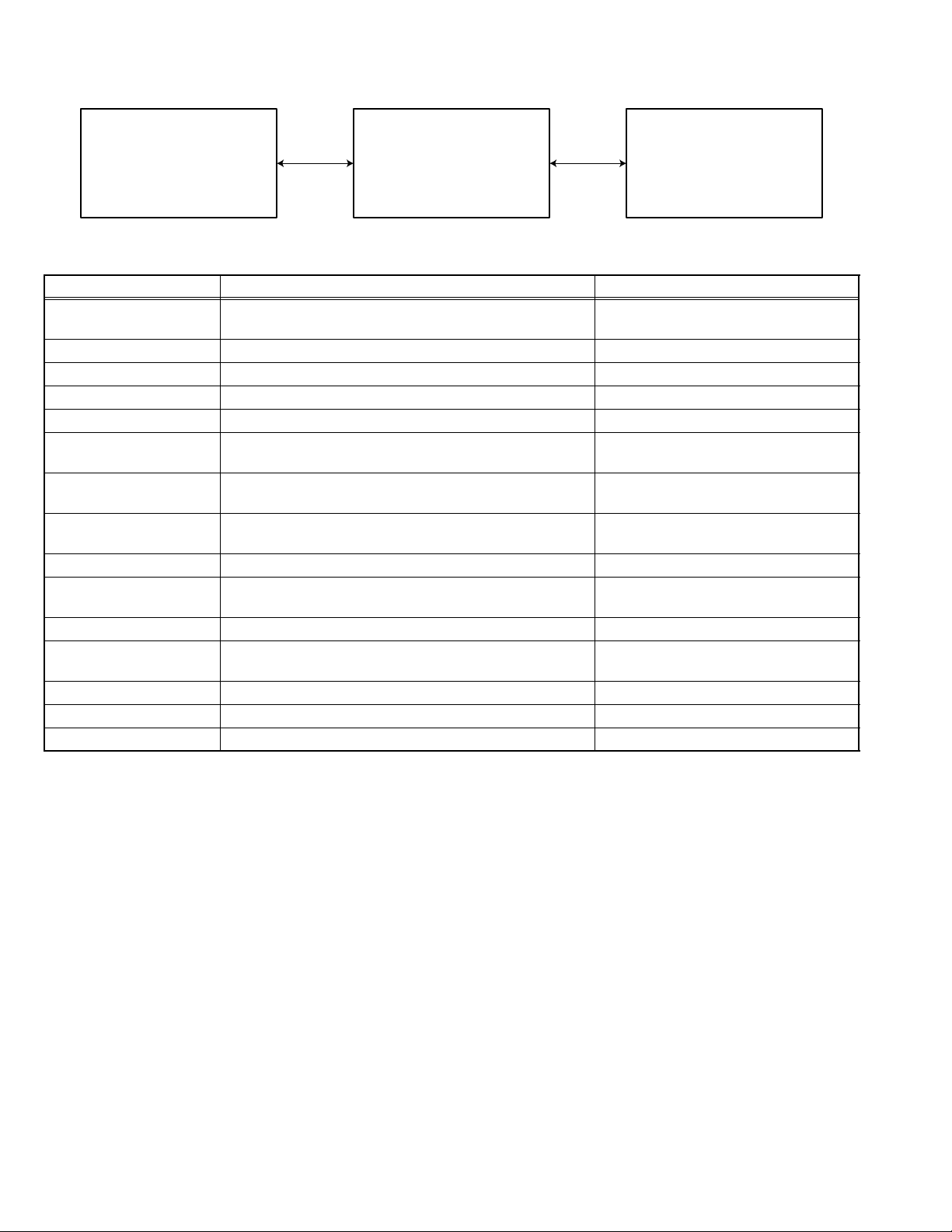
4.8.3 Error codes of panel mechanism
*As for two columns of the beginning of the error code, as for error contents, two columns of middle, number of the pulse counts,
last two columns are a purpose position and movement directions.
Error contents
Time out
Position error by
the external force
Abnormal voltage (1)
Abnormal voltage (2)
Abnormal voltage (3)
Abnormal voltage (4)
code
OB
OC
F3
F5
F7
F8
When assumed last two columns XY;, as for X, as for purpose position,
Y, is a movement direction.
Purpose position
CLOSE
5 degrees
10 degrees
15 degrees
20 degrees
25 degrees
30 degrees
OPEN
Detail
X
1
2
3
4
5
6
7
8
Movement direction
Open direction
Close direction
Error code
(Service mode)
It is time-out during movement to the closed position. 0B**11
It is time-out during 5 degrees tilt movement.(open direction) 0B**20
It is time-out during 5 degrees tilt movement.(close direction) 0B**21
It is time-out during 10 degrees tilt movement.(open direction) 0B**30
It is time-out during 10 degrees tilt movement.(close direction) 0B**31
It is time-out during 15 degrees tilt movement.(open direction) 0B**40
It is time-out during 15 degrees tilt movement.(close direction) 0B**41
It is time-out during 20 degrees tilt movement.(open direction) 0B**50
It is time-out during 20 degrees tilt movement.(close direction) 0B**51
It is time-out during 25 degrees tilt movement.(open direction) 0B**60
It is time-out during 25 degrees tilt movement.(close direction) 0B**61
It is time-out during 30 degrees tilt movement.(open direction) 0B**70
It is time-out during 30 degrees tilt movement.(close direction) 0B**71
It is time-out during movement to the open position. 0B**80
It is time-out during movement to the open position. 0B**80
It is position error during close position stop. 0C0011
It is position error during 5 degree tilt position stop. 0C0020
It is position error during 10 degree tilt position stop. 0C0030
It is position error during 15 degree tilt position stop. 0C0040
It is position error during 20 degree tilt position stop. 0C0050
It is position error during 25 degree tilt position stop. 0C0060
It is position error during 30 degree tilt position stop. 0C0070
It is position error during open position stop. 0C0080
Detect abnormal voltage (1) F3**XY
Detect abnormal voltage (2) F5**XY
Detect abnormal voltage (3) F7**XY
Detect abnormal voltage (4) F8**XY
Y
0
1
Note: "**" of the above error code is the number of the pulse counts at the time of the error outbreak.
1-26 (No.MA443<Rev.001>)
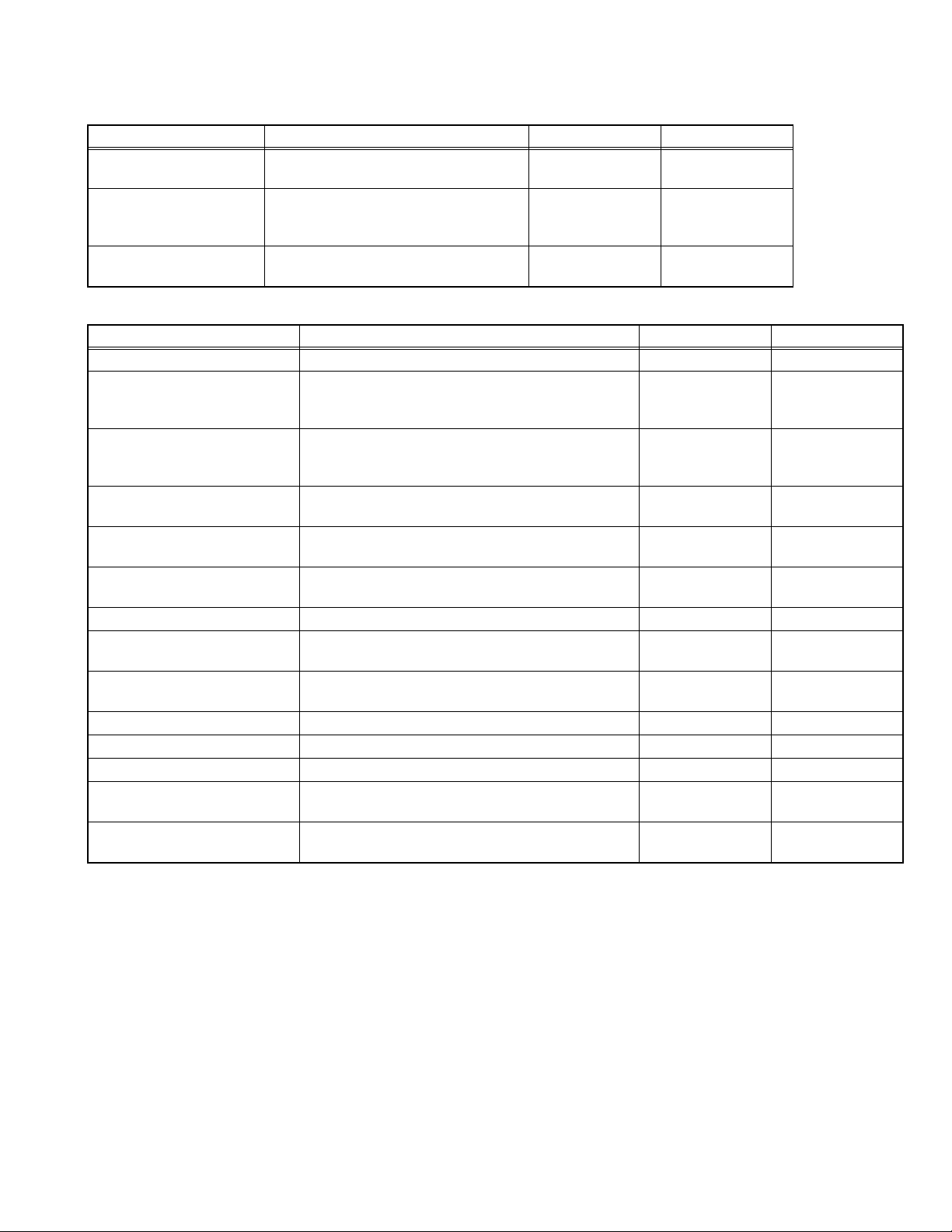
4.9 Running mode
In
Indication Explanation Operation contents of 1 cycle
mech
a er-
ror
↔
RUNNING1 MECHA Door mecha running 1 Panel close
RUNNING2 MECHA Door mecha running 2 Panel close
25 degrees → 30 degrees → Panel open
RUNNING3 MECHA Door mecha running 3 Panel
→
Panel close
RUNNING4 DVD DVD+Door mecha running1 Loading
RUNNING5 DVD DVD+Door mecha running2 Loading
RUNNING6 DVD DVD+Door mecha running3 Loading
RUNNING7 DVD DVD+Door mecha running4 Loading
RUNNING8 DVD DVD+Door mecha running5 Loading
RUNNING9 DVD DVD+Door mecha running6 Loading
Panel open - -
→
5 degrees → 10 degrees → 15 degrees → 20 degrees
close → 5 degrees →
→
Eject → Wait for 5 seconds+Door open/close Stop -
→
Eject → Wait for 5 seconds+Door open/close Retry -
→
Playback → Eject → Wait for 5 seconds+Door open/close Stop Stop
→
Playback → Eject → Wait for 5 seconds+Door open/close Retry Stop
→
Playback → Eject → Wait for 5 seconds+Door open/close Stop Retry
→
Playback → Eject → Wait for 5 seconds+Door open/close Retry Retry
····
→ 30 degrees →
····
→ 5 degrees
→
--
→
--
* Cancellation of running1,2 and 3 : Press the [EJECT] key
* In running 1,2 and 3 cancellation, a door does not stop at the position and moves to a panel position.
* Cancellation of running4 to 9 : Press the [POWER] key
* The number of count and an error cord are displayed in running.
Playback contents in a running mode
•CD
The first track is played for 30 seconds.
→ The last track is played for 30 seconds.
(The last track is played in the case of less than till the last for 30 seconds.)
•DVD
2layer disc (Pit disc)
Title 1 (the L0 layer internal circumference) is played for 30 seconds.
→ Title 24 (L1layer internal circumference) is played for 30 seconds.
→ Title 12 (L0 layer circumference) is played for 30 seconds.
2layer disc (Recordable disc)
Title 1 (the L0 layer internal circumference) is played for 30 seconds. → Title 13 (L0 layer circumference) is played for 30 seconds.
→ Title 24 (L1layer internal circumference) is played for 30 seconds.
1layer disc
First chapter of title 1 is played for 30 seconds.
→ The last chapter of title 1 is played for 30 seconds
In
disc
error
(No.MA443<Rev.001>)1-27
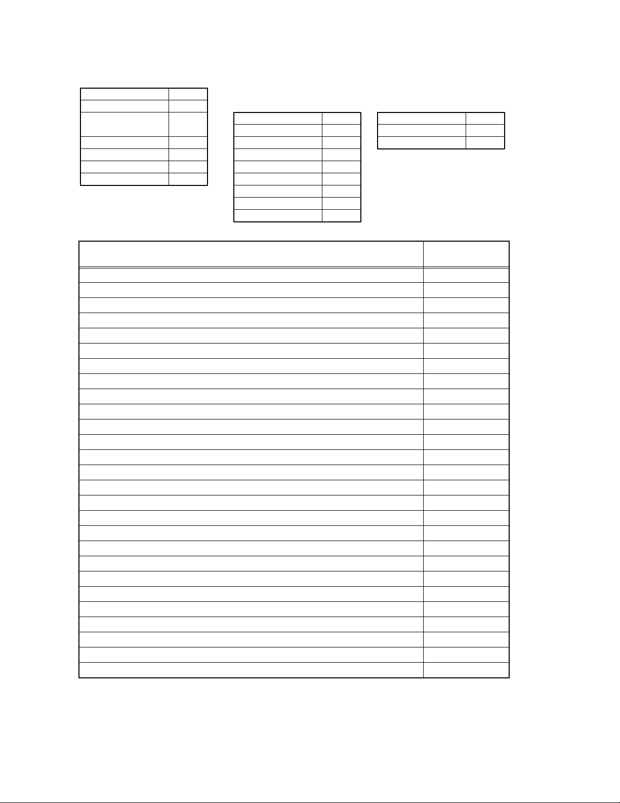
4.10 Monitor adjustment
* When adjusting, switch on the main unit and insert a test disc (VT-501). And play the test disc and pause it.
1. Set the service mode 4.
2. Exchanging it operate a menu of a service mode with the [UP] button and [DOWN] button.
3. Change data with the [B.SKIP]/[F.SKIP] buttons.
4. Write data with a [ENTER] button.
R/W CHROMA
Indication
00001 00000 00001 00000 00000 Fix Color amplitude revision ON/OFF
00002 00000 00003 00000 00000 Fix Color amplitude revision CAS
00003 00000 00063 00000 00000 Fix Color amplitude revision APC
00004 00000 00003 00000 00000 Fix Color amplitude revision CUS
00005 00000 00063 00000 00000 Fix Color amplitude revision APU
00006 00000 00001 00000 00000 Fix Black level extension ON/OFF
00007 00000 00001 00001 00001 Fix Black level extension FUNCTION
00008 00000 00511 00176 00176 Fix Black level extension START POINT
00009 00000 00511 00128 00128 Fix Black level extension OFFSET
00010 00000 00255 00128 00128 Adjust Enhancer revision effect adjustment (NTSC)
00011 00000 00255 00128 00128 Adjust Enhancer revision effect adjustment (PAL)
00012 00000 00255 00064 00064 Adjust Limiter of the horizontal enhancer (NTSC)
00013 00000 00255 00068 00068 Adjust Limiter of the horizontal enhancer (PAL)
00014 00000 00255 00000 00000 Adjust Filter choice of the horizontal enhancer (NTSC)
00015 00000 00255 00000 00000 Adjust Filter choice of the horizontal enhancer (PAL)
00016 00000 00003 00001 00001 Adjust Tap change of the brightness outline revision (NTSC)
00017 00000 00003 00001 00001 Adjust Tap change of the brightness outline revision (PAL)
00018 00000 00127 00000 00000 Adjust Adjustment of the quantity of brightness outline core ring (NTSC)
00019 00000 00127 00000 00000 Adjust Adjustment of the quantity of brightness outline core ring (PAL)
00020 00000 00006 00000 00000 Adjust Adjustment of the brightness outline revision gain (NTSC)
00021 00000 00006 00000 00000 Adjust Adjustment of the brightness outline revision gain (PAL)
00022 00000 00255 00125 00125 Fix Change in TINT of the whole picture (NTSC)
00023 00000 00255 00125 00125 Fix Change in TINT of the whole picture (PAL)
00024 00000 00255 00090 00090 Fix Change with the deepness of the color of the whole picture (NTSC)
00025 00000 00255 00100 00100 Fix Change with the deepness of the color of the whole picture (PAL)
00026 00000 00255 00131 00131 Adjust Tint adjustment (NTSC)
00027 00000 00255 00131 00131 Adjust Tint adjustment (PAL)
00028 00000 00255 00051 00051 Adjust Color adjustment (NTSC)
00029 00000 00255 00051 00051 Adjust Color adjustment (PAL)
00030 00000 00511 00094 00094 Fix Set the offset DC of the input video signal (NTSC)
00031 00000 00511 00094 00094 Fix Set the offset DC of the input video signal (PAL)
00032 00000 00001 00000 00000 Fix Quantity of transmission revision of the YUV DC
00033 00000 00255 00016 00016 Fix Quantity of transmission revision of the YUV DC
00034 00000 01023 00320 00320 Adjust Contrast adjustment between the black - white (NTSC)
00035 00000 01023 00322 00322 Adjust Contrast adjustment between the black - white (PAL)
00036 00000 00511 00348 00348 Fix Conversion coefficients from YUV to RGB (PRCL)
00037 00000 00255 00210 00210 Fix Conversion coefficients from YUV to RGB (PBCL)
00038 00000 00255 00210 00210 Fix Conversion coefficients from YUV to RGB (YCL)
00039 00000 00255 00158 00158 Fix Conversion coefficients from YUV to RGB (BCL)
00040 00000 00511 00267 00267 Fix Conversion coefficients from YUV to RGB (RCL)
00041 00000 00001 00001 00001 Fix Noise shaving (NTSC)
00042 00000 00001 00001 00001 Fix Noise shaving (PAL)
00043 00000 00127 00029 00029 Adjust Black level adjustment (NTSC)
00044 00000 00127 00028 00028 Adjust Black level adjustment (PAL)
Minimum
value
Maximum
value
Initial
value
Reference
register
value
Detail
1-28 (No.MA443<Rev.001>)

Indication
00045 00000 00127 00058 00058 Fix Gain setting of Red signal (NTSC)
00046 00000 00127 00059 00057 Fix Gain setting of Red signal (PAL)
00047 00000 00127 00057 00057 Fix Gain setting of Green signal (NTSC)
00048 00000 00127 00059 00056 Fix Gain setting of Green signal (PAL)
00049 00000 00127 00054 00054 Fix Gain setting of Blue signal (NTSC)
00050 00000 00127 00053 00053 Fix Gain setting of Blue signal (PAL)
00051 00000 00127 00061 00061 Fix Set the cut-off of the Red signal (NTSC)
00052 00000 00127 00061 00061 Fix Set the cut-off of the Red signal (PAL)
00053 00000 00127 00061 00061 Fix Set the cut-off of the Green signal (NTSC)
00054 00000 00127 00061 00061 Fix Set the cut-off of the Green signal (PAL)
00055 00000 00127 00061 00061 Fix Set the cut-off of the Blue signal (NTSC)
00056 00000 00127 00061 00061 Fix Set the cut-off of the Blue signal (PAL)
00057 00000 00001 00001 00001 Fix ON/OFF change of the gamma revision
00058 00000 00255 00007 00007 Fix Adjust 1 gamma revision point position of a Red signal
00059 00000 00255 00015 00015 Fix Adjust 2 gamma revision point position of a Red signal
00060 00000 00255 00023 00023 Fix Adjust 3 gamma revision point position of a Red signal
00061 00000 00255 00031 00031 Fix Adjust 4 gamma revision point position of a Red signal
00062 00000 00255 00039 00039 Fix Adjust 5 gamma revision point position of a Red signal
00063 00000 00255 00047 00047 Fix Adjust 6 gamma revision point position of a Red signal
00064 00000 00255 00055 00055 Fix Adjust 7 gamma revision point position of a Red signal
00065 00000 00255 00017 00017 Fix Appoint gamma revision gain 1 of the Red signal
00066 00000 00255 00031 00031 Fix Appoint gamma revision gain 2 of the Red signal
00067 00000 00255 00032 00032 Fix Appoint gamma revision gain 3 of the Red signal
00068 00000 00255 00032 00032 Fix Appoint gamma revision gain 4 of the Red signal
00069 00000 00255 00036 00036 Fix Appoint gamma revision gain 5 of the Red signal
00070 00000 00255 00042 00042 Fix Appoint gamma revision gain 6 of the Red signal
00071 00000 00255 00058 00058 Fix Appoint gamma revision gain 7 of the Red signal
00072 00000 00255 00088 00088 Fix Appoint gamma revision gain 8 of the Red signal
00073 00000 00255 00007 00007 Fix Adjust 1 gamma revision point position of a Green signal
00074 00000 00255 00015 00015 Fix Adjust 2 gamma revision point position of a Green signal
00075 00000 00255 00023 00023 Fix Adjust 3 gamma revision point position of a Green signal
00076 00000 00255 00031 00031 Fix Adjust 4 gamma revision point position of a Green signal
00077 00000 00255 00039 00039 Fix Adjust 5 gamma revision point position of a Green signal
00078 00000 00255 00047 00047 Fix Adjust 6 gamma revision point position of a Green signal
00079 00000 00255 00055 00055 Fix Adjust 7 gamma revision point position of a Green signal
00080 00000 00255 00017 00017 Fix Appoint gamma revision gain 1 of the Green signal
00081 00000 00255 00031 00031 Fix Appoint gamma revision gain 2 of the Green signal
00082 00000 00255 00032 00032 Fix Appoint gamma revision gain 3 of the Green signal
00083 00000 00255 00032 00032 Fix Appoint gamma revision gain 4 of the Green signal
00084 00000 00255 00036 00036 Fix Appoint gamma revision gain 5 of the Green signal
00085 00000 00255 00042 00042 Fix Appoint gamma revision gain 6 of the Green signal
00086 00000 00255 00058 00058 Fix Appoint gamma revision gain 7 of the Green signal
00087 00000 00255 00088 00088 Fix Appoint gamma revision gain 8 of the Green signal
00088 00000 00255 00007 00007 Fix Adjust 1 gamma revision point position of a Blue signal
00089 00000 00255 00015 00015 Fix Adjust 2 gamma revision point position of a Blue signal
00090 00000 00255 00023 00023 Fix Adjust 3 gamma revision point position of a Blue signal
00091 00000 00255 00031 00031 Fix Adjust 4 gamma revision point position of a Blue signal
00092 00000 00255 00039 00039 Fix Adjust 5 gamma revision point position of a Blue signal
00093 00000 00255 00047 00047 Fix Adjust 6 gamma revision point position of a Blue signal
00094 00000 00255 00055 00055 Fix Adjust 7 gamma revision point position of a Blue signal
Minimum
value
Maximum
value
Initial
value
Reference
register
value
Detail
(No.MA443<Rev.001>)1-29
Indication
00095 00000 00255 00017 00017 Fix Appoint gamma revision gain 1 of the Blue signal
00096 00000 00255 00031 00031 Fix Appoint gamma revision gain 2 of the Blue signal
00097 00000 00255 00032 00032 Fix Appoint gamma revision gain 3 of the Blue signal
00098 00000 00255 00032 00032 Fix Appoint gamma revision gain 4 of the Blue signal
00099 00000 00255 00036 00036 Fix Appoint gamma revision gain 5 of the Blue signal
00100 00000 00255 00042 00042 Fix Appoint gamma revision gain 6 of the Blue signal
00101 00000 00255 00058 00058 Fix Appoint gamma revision gain 7 of the Blue signal
00102 00000 00255 00088 00088 Fix Appoint gamma revision gain 8 of the Blue signal
00103 00000 00255 00060 00060 Adjust Adjust the horizontal indication point of the picture (NTSC)
00104 00000 00255 00060 00060 Adjust Adjust the horizontal indication point of the picture (PAL)
00105 00000 00255 00010 00010 Adjust Adjust the vertical indication point of the picture (NTSC)
00106 00000 00255 00010 00010 Adjust Adjust the vertical indication point of the picture (PAL)
00107 00000 00127 00042 00042 Fix AD clock gain adjustment (NTSC)
00108 00000 00127 00042 00042 Fix AD clock gain adjustment (PAL)
00109 00000 00007 00001 00001 Fix Noise reduction of the Y signal (NTSC)
00110 00000 00007 00001 00001 Fix Noise reduction of the Y signal (PAL)
00111 00000 00003 00032 00032 Fix Choose a YC separation filter (NTSC)
00112 00000 00003 00048 00048 Fix Choose a YC separation filter (PAL)
00113 00000 00007 00000 00000 Fix Color pulling out filter setting (NTSC)
00114 00000 00007 00000 00000 Fix Color pulling out filter setting (PAL)
00115 00000 00007 00001 00001 Adjust Choose com movement mode and color BPF (NTSC)
00116 00000 00007 00004 00004 Adjust Choose com movement mode and color BPF (PAL)
00117 00000 01023 00180 00180 Fix Vertical dot cancellation setting (NTSC)
00118 00000 01023 00180 00180 Fix Vertical dot cancellation setting (PAL)
00119 00000 00063 00001 00001 Adjust Noise reduction setting (NTSC)
00120 00000 00063 00001 00001 Adjust Noise reduction setting (PAL)
00121 00000 01023 00338 00338 Fix Quantity of brightness adjustment setting (NTSC)
00122 00000 01023 00338 00338 Fix Quantity of brightness adjustment setting (PAL)
00123 00000 00255 00168 00168 Fix Brightness gain adjustment (NTSC)
00124 00000 00255 00168 00168 Fix Brightness gain adjustment (PAL)
00125 00000 00511 00140 00140 Adjust Color signal output level setting (NTSC)
00126 00000 00511 00096 00096 Adjust Color signal output level setting (PAL)
00127 00000 00006 00004 00004 Fix ACC movement mode setting
00128 00000 00255 00033 00033 Fix C signal filter characteristic setting of the Y/C separation part (NTSC)
00129 00000 00255 00033 00033 Fix C signal filter characteristic setting of the Y/C separation part (PAL)
00130 00000 16383 02464 02464 Fix Amplitude killer off level setting
00131 00000 16383 02472 02472 Fix Amplitude killer on level setting
00132 00000 00127 00071 00071 Fix Clamp DC level adjustment setting
00133 00000 00015 00015 00015 Fix Clamp speed adjustment setting
00134 00000 00063 00049 00049 Fix Noise filter band setting of horizontal synchronization signal and verti-
00135 00000 00063 00049 00049 Fix Noise filter band setting of horizontal synchronization signal and verti-
00136 00000 65535 14976 14976 Fix Horizontal phase comparison gain setting (NTSC)
00137 00000 65535 14976 14976 Fix Horizontal phase comparison gain setting (PAL)
00138 00000 00063 00055 00055 Fix Horizontal loop filter setting 1
00139 00000 00015 00010 00010 Fix Horizontal loop filter setting 2
00140 00000 00015 00007 00007 Fix Horizontal loop filter setting 3
00141 00000 00015 00001 00001 Fix Synchronization separation burst clock setting (NTSC)
00142 00000 00015 00001 00001 Fix Synchronization separation burst clock setting (PAL)
Minimum
value
Maximum
value
Initial
value
Reference
register
value
Detail
cal synchronizing signal (NTSC)
cal synchronizing signal (PAL)
1-30 (No.MA443<Rev.001>)
 Loading...