


 Loading...
JVC GR-FX17EK, GR-FX17EX, GR-FX17EY, GR-FX17EZ, GR-SX170AG User Manual
...PAL
AUTOMATIC DEMONSTRATION
Automatic Demonstration takes place when “DEMO MODE” is set to “ON” (factory-preset).
•Available when the Power Switch is set to “ ” or “
 ”.
”.
•To cancel Automatic Demonstration, set "DEMO MODE" to "OFF" ( pg. 14).
COMPACT VHS CAMCORDER
GR-FXM41
GR-FX17
CONTENTS
GETTING STARTED |
4 ~ 8 |
RECORDING/PLAYBACK |
9 |
|
|
BASIC FEATURES |
9 ~ 11 |
|
|
MENU SETTINGS |
12 ~ 15 |
|
|
TERMS |
20 |
|
|
Dear Customer,
Thank you for purchasing the JVC Compact VHS camcorder. Before use, please read “SAFETY PRECAUTIONS” ( pg. 2, 3) to ensure safe use of this product.
INSTRUCTIONS
ENGLISH
LYT1359-001B
ACCESSORIES |
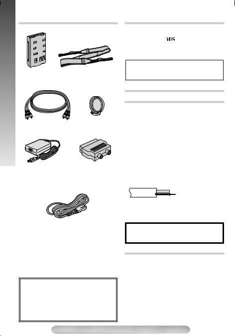
PROVIDED ACCESSORIES |
|
|
||
PROVIDED |
Battery Pack |
Shoulder Strap |
|
||
BN-V10U
Lens Cap
A/V (Audio/Video)
Cable
AC Adapter |
Cable Adapter |
AP-V14E |
|
Power Cord
NOTE:
In order to maintain optimum performance of the camcorder, provided cables may be equipped with one or more core filter. If a cable has only one core filter, the end that is closest to the filter should be connected to the camcorder.
OPTIONAL ACCESSORIES
•Battery Packs BN-V12U, BN-V20U, BNV400U
• Compact VHS ( |
|
|
) Cassettes EC-60/ |
45/30 |
|
|
|
•Active Carrying Bag CB-V7U
•Cassette Adapter C-P8U
Some accessories are not available in some areas. Please consult your nearest JVC dealer for details on accessories and their availability.
SAFETY PRECAUTIONS
IMPORTANT
Connection to the mains supply in the United Kingdom. DO NOT cut off the mains plug from this equipment.
If the plug fitted is not suitable for the power points in your home or the cable is too short to reach a power point, then obtain an appropriate safety approved extension lead or consult your dealer.
BE SURE to replace the fuse only with an identical approved type, as originally fitted, and to replace the fuse cover.
If nonetheless the mains plug is cut off be sure to remove the fuse and dispose of the plug immediately, to avoid possible shock hazard by inadvertent connection to the mains supply. If this product is not supplied fitted with a mains plug then follow the instructions given below:
DO NOT make any connection to the Larger Terminal coded E or Green.
The wires in the mains lead are coloured in accordance with the following code:
 Blue to N (Neutral) or Black
Brown to L (Live) or Red
If these colours do not correspond with the terminal identifications of your plug, connect as follows:
Blue wire to terminal coded N (Neutral) or coloured black. Brown wire to terminal coded L (Live) or coloured Red.
If in doubt — consult a competent electrician.
WARNING:
TO PREVENT FIRE OR SHOCK HAZARD, DO NOT EXPOSE THIS UNIT TO RAIN OR MOISTURE.
CAUTIONS
•To prevent shock, do not open the cabinet. No user serviceable parts inside. Refer servicing to qualified personnel.
•When you are not using the AC Adapter for a long period of time, it is recommended that you disconnect the power cord from AC outlet.
NOTES:
•The rating plate (serial number plate) and safety caution are on the bottom and/or the back of the main unit.
•The rating information and safety caution of the AC Adapter are on its bottom.
2
CAUTIONS
•This camcorder is designed to be used with PAL-type colour television signals. It cannot be used for playback with a television of a different standard. However, live recording and LCD monitor*/ viewfinder playback are possible anywhere.
•Use the JVC BN-V10U/ V12U/ V20U/ V400U battery packs and, to recharge them or to supply power to the camcorder from an AC outlet, use the provided multi-voltage AC Adapter.
(An appropriate conversion adapter may be necessary to accommodate different designs of AC outlets in different countries.)
* GR-FXM41 only.
CAUTIONS
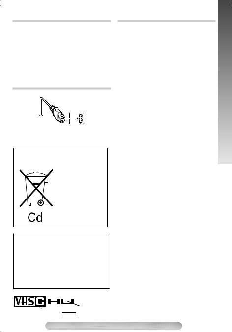
To avoid electric shock or damage to the unit, first, firmly insert the small end of the power cord into the AC Adapter until it is no longer wobbly, and then plug the larger end of the power cord into an AC outlet.
Crossed Out Dust Bin Mark
For BNV12U (optional)
• The Crossed Out Dust Bin Mark on the battery pack indicates that the product complies with Directives 91/ 157/ EEC and 93/ 86/ EEC.
• Nickel Cadmium (Ni-Cd) battery pack must be recycled or disposed of properly.
When the equipment is installed in a cabinet or on a shelf, make sure that it has sufficient space at least 10cm on all sides to allow ventilation.
Do not block the ventilation holes.
No naked flame sources, such as lighted candles, should be placed on the apparatus.
When discarding batteries, environmental problems must be considered and the local rules or laws governing the disposal of these batteries must be followed strictly.
Prevent water or liquid from entering this equipment, keep it away from wet places.
SOME DO’S AND DON’TS ONTHE SAFE USE OF EQUIPMENT
This equipment has been designed and manufactured to meet international safety standards but, like any electrical equipment, care must be taken if you are to obtain the best results and safety is to be assured.
DO read the operating instructions before you attempt to use the equipment.
DO ensure that all electrical connections (including the mains plug, extension leads and interconnections between pieces of equipment) are properly made and in accordance with the manufacturer’s instructions. Switch off and withdraw the mains plug when making or changing connections.
DO consult your dealer if you are ever in doubt about the installation, operation or safety of your equipment.
DO be careful with glass panels or doors on equipment.
DON’T continue to operate the equipment if you are in any doubt about it working normally, or if it is damaged in any way — switch off, withdraw the mains plug and consult your dealer.
DON’T remove any fixed cover as this may expose dangerous voltages.
DON’T leave equipment switched on when it is unattended unless it is specifically stated that it is designed for unattended operation or has a standby mode. Switch off using the switch on the equipment and make sure that your family knows how to do this. Special arrangements may need to be made for infirm or handicapped people.
DON’T use equipment such as personal stereos or radios so that you are distracted from the requirements of road safety. It is illegal to watch television whilst driving.
DON’T listen to headphones at high volume, as such use can permanently damage your hearing.
DON’T obstruct the ventilation of the equipment, for example with curtains or soft furnishings. Overheating will cause damage and shorten the life of the equipment.
DON’T use makeshift stands and NEVER fix legs with wood screws — to ensure complete safety always fit the manufacturer’s approved stand or legs with the fixings provided according to the instructions.
DON’T allow electrical equipment to be exposed to rain or moisture.
ABOVE ALL
—NEVER let anyone especially children push anything into holes, slots or any other opening in the case — this could result in a fatal electrical shock;
—NEVER guess or take chances with electrical equipment of any kind — it is better to be safe than sorry!
SAFETY PRECAUTIONS
Only cassettes marked
 can be used with this camcorder.
3

GETTING STARTED
CONTROLS, CONNECTORS AND INDICATORS
Refer to this diagram while reading the instructions.
Eyepiece 51 2 34
During |
|
|
shooting |
$ % & |
( |
|
Connector |
|
|
Cover |
Keep the lens |
|
6 |
|
|
cap attached to |
|
|
|
|
|
7 |
the camcorder |
|
5 |
Cassette holder |
) |
|
||
8 |
|
|
9 |
! " # |
|
Viewfinder
 90¡
90¡
Speaker 180 (GR-FXM41

 only)
only)
~
LCD monitor (GR-FXM41 only)
,
+
Turn the gear to take up slack
-Erase protection tab
Microphone
LCD Monitor/Viewfinder Indications
During Recording |
During Playback |
|
|
. / : |
; |
|
|
< |
|
0 1 |
2 34 5 |
|
= |
|
120M I N |
T30 |
|
|
|
|
|
SP |
|
|
REC SP |
|
|
{ |
|
|
TBC |
—1 : 2 3 : 4 5 |
|
|
? > |
|
+02 |
| |
|
|
|
AT |
|
||
|
} |
|
|
|
|
|
||||
[ |
@ |
|
MWB |
|
|
|
|
|
|
|
PAUSE |
|
|
1 X |
|
|
|
|
|||
|
\ |
5M I N |
1 / 2S |
V |
|
|
|
|
|
|
] |
|
|
|
|
|
|
|
|
||
^ |
CONGRATULAT I ONS |
|
|
|
|
|
|
6 |
||
|
25. 12. 04 |
11 : 45 : 18 |
|
|
b |
a |
VOLUME — ————— ————— + |
|||
_ |
|
BR I GHT — ——————— ——— + |
|
|
|
|||||
pg. 16 for “Warning Indications”
4

1• MENU Wheel [–, +]............................. |
|
|
pg. 12 |
• BRIGHT Wheel [–, +]*........................ |
|
|
pg. 14 |
• Speaker Volume Control [VOL.]*.......... |
|
pg. 9 |
|
• TRACKING Wheel [–, +]..................... |
|
|
pg. 10 |
25- Second Recording Button................... |
|
pg. 9 |
|
[5 SEC. REC] |
|
|
|
3Power Zoom Lever [T/W] ...................... |
|
|
pg. 10 |
4•Manual Focus Button [ |
FOCUS] |
...... |
pg. 9 |
• Time Base Corrector Button (TBC) |
.... |
pg. 10 |
|
5Shoulder Strap Eyelets ........................... |
|
|
pg. 8 |
6Audio Output Connector [A] |
............ |
pg. 10, 11 |
|
7Video Output Connector [V] |
............ |
pg. 10, 11 |
|
8Battery Release Switch .......................... |
|
|
pg. 6 |
[BATTERY RELEASE] |
|
|
|
9DC IN Connector .................................... |
|
|
pg. 6 |
!• Recording Start/Stop Button................. |
|
pg. 9 |
|
• REFRESH Button ................................ |
|
|
pg. 6 |
"Lock Button............................................. |
|
|
pg. 6 |
#Power Switch [ PLAY, OFF, |
, |
] .... |
pg. 9 |
$POWER/CHARGE Lamp........................ |
|
|
pg. 6 |
%• Retake Forward Button [RETAKE F]... |
pg. 10 |
||
• FastForward Button [F] ...................... |
|
|
pg. 9 |
&• Play/ Pause Button ............................... |
|
|
pg. 9 |
• Backlight Compensation Button ........... |
|
pg. 9 |
|
(• Stop Button [STOP] .............................. |
|
|
pg. 9 |
• Eject Button [EJECT] ........................... |
|
|
pg. 8 |
)• Retake Rewind Button [RETAKE R] ... |
pg. 10 |
||
• Quick Review Button [ |
R ].......... |
|
pg. 10 |
• Rewind Button [R] ................................ |
|
|
pg. 9 |
~Close Button ........................................... |
|
|
pg. 8 |
+Dioptre Adjustment Control..................... |
|
|
pg. 8 |
,Grip Strap ............................................... |
|
|
pg. 8 |
-Tripod Mounting Socket .......................... |
|
|
pg. 8 |
.Tape Remaining Time ........................... |
|
|
pg. 14 |
/Recording Mode Indicator..................... |
|
|
pg. 13 |
:Backlight Compensation Indicator .......... |
|
pg. 9 |
|
;Tape Length Indicator............................ |
pg. 15 |
||
<Zoom Indicator Bar................................ |
pg. 10 |
||
|
a Zoom Level Indicator |
|
|
|
b Approximate Zoom Ratio |
|
|
=Recording Indicator ................................. |
pg. 9 |
||
>Digital Effect Indicator ........................... |
pg. 12 |
||
?Programme AE Indicator ....................... |
pg. 12 |
||
@Fade/Wipe-Standby Indicator ................ |
pg. 13 |
||
[Picture Stabiliser Indicator..................... |
pg. 13 |
||
\• Interval Time/Recording Time Indicator ... |
pg. 15 |
||
|
• 5 Sec. Rec Mode Indicator.................... |
pg. 9 |
|
]Instant Title Display ............................... |
pg. 14 |
||
^Date/Time Display ................................. |
pg. 14 |
||
_Bright Level Indicator* ........................... |
pg. 14 |
||
{Focus Indicator........................................ |
pg. 9 |
||
|Exposure Control Level Counter ........... |
pg. 12 |
||
}White Balance Mode Indicator .............. |
pg. 13 |
||
VRecord-Standby Mode Indicator.............. |
pg. 9 |
||
0 |
|
: Cassette Indicator |
pg. 8 |
|
|||
1TBC indicator......................................... |
pg. 10 |
||
2Tape Counter......................................... |
pg. 15 |
||
3Recording Mode Indicator (SP/ LP)....... |
pg. 13 |
||
4Tape Running Indicator |
|
||
|
3: Playback |
|
|
|
¡: FastForward/Shuttle Search |
|
|
|
1: Rewind/ Shuttle Search |
|
|
|
8: Pause |
|
|
5Tracking Indicator .................................. |
pg. 14 |
||
6VOLUME: Speaker Volume Indicator* ...... |
pg. 9 |
||
* GR-FXM41 only.
GETTING STARTED
5
STARTED |
GETTING STARTED |
|
|
GETTING |
Hook on |
BATTERY RELEASE |
|
|
Push in |
|
Power Switch |
|
Switch |
|
Battery pack |
|
To AC outlet |
|
To DC IN |
|
connector |
|
AC Adapter |
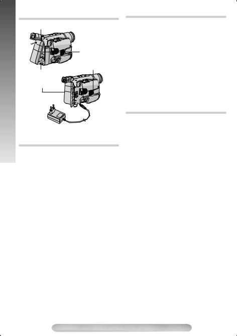
Charging the Battery Pack
1)Hook the end of the battery pack to the camcorder and push the battery in until it locks
in place.
•If the battery pack is attached wrongly, a malfunction may occur.
2)Set the Power Switch # to “OFF” while pressing down the Lock Button ". Connect the AC Adapter to the DC IN connector 9, then connect the Power Cord to the AC Adapter.
3)Plug the Power Cord into an AC outlet.The CHARGE lamp $ blinks to indicate charging.
4)When the CHARGE lamp $ stops blinking and turns off, charging is finished. Unplug the AC Adapter from the AC outlet. Disconnect the AC Adapter from the camcorder.
To Detach The Battery Pack…
… slide BATTERY RELEASE 8 and pull out the battery pack.
Battery Pack |
Charging time |
BN-V10U |
approx. 1 hr. 30 min. |
|
|
BN-V12U (optional) |
approx. 1 hr. 40 min. |
|
|
BN-V20U (optional) |
approx. 2 hrs. 40 min. |
|
|
BN-V400U (optional) |
approx. 5 hrs. 10 min. |
|
|
Charging time is for a fully discharged battery pack.
Using the Battery Pack
Perform step 1) of “Charging the Battery Pack”.
Approximate recording time (unit: min.)
Battery Pack |
Viewfinder on |
LCD monitor on |
|
|
|
|
|
|
1 |
2 |
1 |
|
|
|
|
BN-V10U |
95 |
100 |
80 |
|
|
|
|
BN-V12U |
100 |
110 |
85 |
(optional) |
|
|
|
|
|
|
|
BN-V20U |
160 |
170 |
140 |
(optional) |
|
|
|
|
|
|
|
BN-V400U |
380 |
410 |
330 |
(optional) |
|
|
|
|
|
|
|
1 When using GR-FXM41
2 When using GR-FX17
Using AC Power
Connect the AC Adapter to the camcorder ( step 2) and 3) of “Charging the Battery Pack”).
•The provided AC Adapter features automatic voltage selection in the AC range from 110V to 240V.
ATTENTION:
Before detaching the power source, make sure that the camcorder’s power is turned off. Failure to do so can cause the camcorder to malfunction.
REFRESH:
Be sure to fully discharge a battery pack before recharging or storing it for a long period of time, otherwise the battery performance will be reduced.
1)Perform steps 1) through 3) of “Charging the Battery Pack”.
2)Press REFRESH ! for over 4 seconds. The CHARGE lamp $ blinks faster to indicate discharging.
3)When discharging is finished, charging automatically starts and the CHARGE lamp $ blinks normally.
6

•The following steps have the same function as “REFRESH” ( pg. 6).
1)Attach the battery to the camcorder with no cassette inserted.
2)Set the Power Switch # to “ ” or “
 ” while pressing down the Lock Button ".
•During charging or discharging, the camcorder cannot be operated.
•Charging and discharging are not possible if the wrong type of battery is used.
•When charging the battery pack for the first time or after a long storage period, the CHARGE lamp $ may not light. Remove the battery pack from the camcorder, then try charging again.
•If a fully-charged battery’s operation time remains extremely short, the battery is worn out. Please purchase a new one.
•Perform charging where the temperature is between 10°C and 35°C. 20°C to 25°C is the ideal temperature range. If the environment is too cold, charging may be incomplete.
•Charging time varies according to the ambient temperature and the status of the battery pack.
•Since the AC Adapter processes electricity internally, it becomes warm during use. Be sure to use it only in well-ventilated areas.
•The following operation stops charging or discharging:
•Set the Power Switch # to “PLAY”, “ ” or “
 ”.
”.
•Disconnect the AC Adapter from the camcorder.
•Unplug the AC Adapter’s power cord from the AC outlet.
•Detach the battery from the camcorder.
•Using the optional AA-V15EG AC Power Adapter/Charger, you can charge the BNV10U/V12U/V20U/V400U battery pack without the camcorder.
However, it cannot be used as an AC adapter.
•To avoid interference with reception, do not use the AC Adapter near a radio.
•Recording time is reduced significantly when Zoom or Record-Standby mode is engaged repeatedly or the LCD monitor* is used repeatedly.
•Before extended use, it is recommended that you prepare enough battery packs to cover 3
times the planned shooting time.
* GR-FXM41 only.
Date/Time Settings
1)Set the Power Switch # to “ ” while pressing down the Lock Button ".
2)Press the MENU Wheel 1 in. The TOP MENU Screen appears.
3)Rotate the MENU Wheel 1 to select “3TO SYSTEM MENU” and press it.
4)Rotate the MENU Wheel 1 to select “3DATE/ TIME SET” and press it. The DATE/TIME SET Menu appears.
5)To set “YEAR”, “MONTH”, “DAY” or “TIME” (hour/minute), rotate the MENU Wheel 1 to select the desired item, and press it. When the setting begins blinking, rotate the MENU Wheel 1 until the correct setting appears and then press it. The setting stops blinking.
6)When none of these settings (“YEAR”, “MONTH”, “DAY”, “TIME”) blinks, rotate the MENU Wheel 1 to select “ 3RETURN” and press it, to go to Menu Screen.
7)Press the MENU Wheel 1 in to select “3EXIT” to close the Menu Screen.
•To display the date and time in the camcorder’s display and on a connected TV, see DATE/ TIME DISP. ( pg. 14) in SYSTEM MENU.
•The date/time cannot be stored in memory if the built-in clock battery runs out. Consult an authorised JVC dealer for replacement, or set the date/time as necessary before you start shooting.
|
|
D A T E T I M E S E T |
24-hour |
|||||
|
Y E A R |
|
|
2 |
0 0 4 |
|
indication |
|
|
M O N T H |
|
|
6 |
|
|
|
|
|
D A Y |
|
|
2 8 |
|
|
|
|
|
T I M E |
2 0 |
: 2 0 |
|
|
|
||
|
R E T URN |
|
|
|
|
|
|
|
GETTING STARTED
7
STARTED |
1) |
|
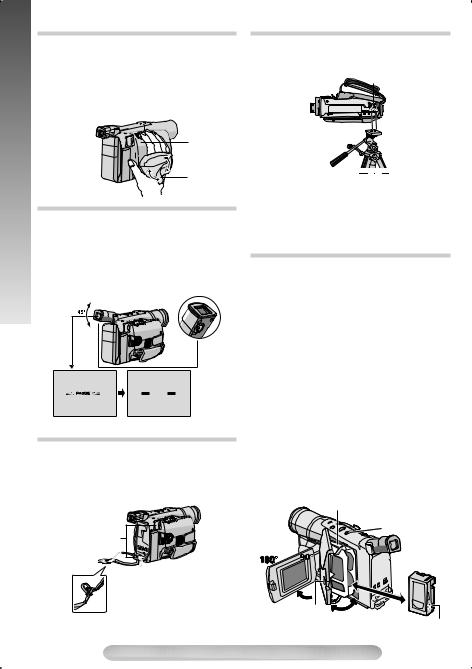
Grip Adjustment |
|
|
|
Separate the Velcro strip. |
|
|
||||
|
|
|
||||
|
2) |
Pass your right hand through the loop and |
||||
|
3) |
grasp the grip. |
|
|
|
|
|
Adjust so that your thumb and fingers can |
|||||
GETTING |
|
easily |
operate |
the Recording |
Start/Stop |
|
|
Button |
! and |
Power Zoom |
" |
3. |
|
|
|
Lever |
||||
Refasten the Velcro strip.


 3 !
3 !


Velcro strip
Viewfinder Adjustment
1)Set the Power Switch # to “ ” or “
 ” while pressing down the Lock Button ".
2)Make sure the LCD monitor* is closed and locked. Pull up the viewfinder and adjust it manually to get the best view.
3)Turn the Dioptre Adjustment Control + until the indications in the viewfinder are clearly focused.
+ |
PAUSE
* GR-FXM41 only.
Shoulder Strap Attachment
Thread the strap through the eyelet 5, then fold it back and thread it through the buckle. Repeat the procedure to attach the other end of the strap to the other eyelet 5, making sure the strap is not twisted. Adjust the length.
5
Tripod Mounting
Align the screw and camera direction stud on the tripod with the tripod mounting socket -. Then tighten the screw.
-
CAUTION:
When using a tripod, be sure to extend its legs fully to stabilise the camcorder. To prevent damage to the unit caused by falling over, do not use a small tripod.
Loading/Unloading A Cassette
1)Open the LCD monitor* fully and keep it aligned vertically with the camera (do not tilt it). Press EJECT ( for more than 2 seconds until the cassette holder opens. Do not force open.
2)When inserting a cassette, make sure the label
is facing outward.  0 appears when a cassette is loaded.
3)Press the Close button ~ to close the cassette holder until it locks in place. Close the LCD monitor*.
•Closing the LCD monitor* while the cassette holder is still open may cause damage to the LCD monitor*.
•Make sure the erase protection tab is in the position that allows recording. If not, slide the tab. Some cassettes have removable tabs. If the tab has been removed, cover the hole with adhesive tape.
•The cassette holder cannot be opened while the camcorder is in record mode or detached
from power source.
* GR-FXM41 only.
Cassette holder
(
 90¡
90¡
~
Erase protection tab
8
Loading...