


GR-DVL805
LYT0575-001B
EN
DIGITAL VIDEO CAMERA
INSTRUCTIONS
GR-DVL805
GR-DVL505
For Customer Use:
Enter below the Model No. and Serial No. which is located on the
bottom of cabinet. Retain this information for future reference.
Model No.
Serial No.
ENGLISH
CONTENTS
AUTOMATIC DEMONSTRATION
7
GETTING STARTED
8 – 15
RECORDING
16 – 32
Basic Recording For Video .................... 16
Basic Recording For
Digital Still Camera (D.S.C.) ................ 19
Basic Recording For Video And D.S.C. ...... 20
Advanced Features For
Video And D.S.C. ............................. 23
PLAYBACK
33 – 41
Basic Playback For Video ..................... 33
Advanced Features For Video ................ 34
Basic Playback For D.S.C. ..................... 36
Advanced Features For D.S.C. ............... 38
CONNECTIONS
42 – 45
Basic Connections .............................. 42
Advanced Connections ......................... 44
DUBBING
46 – 49
Dubbing To A VCR ............................. 46
Dubbing To Or From A Video Unit
Equipped With A DV Connector ............ 47
Dubbing Images Stored In
The Built-in Memory To A Tape ............ 48
Dubbing Images Recorded On A Tape To
The Built-in Memory ......................... 4 9
USING THE REMOTE
CONTROL UNIT
50 – 61
Slow-Motion Playback, Frame-By-Frame
Playback and Playback Zoom .............. 52
Playback Special Effects ...................... 53
Random Assemble Editing .................... 54
For More Accurate Editing .................... 58
Audio Dubbing .................................. 60
Insert Editing ................................... 61
TROUBLESHOOTING
62 – 68
INDEX
69 – 75
Indications ...................................... 69
Controls, Connectors And Indicators ........ 74
USER MAINTENANCE
76
CAUTIONS
77 – 79
TERMS
80 – 81
SPECIFICATIONS
82 – 83
Please visit our Homepage on the World Wide
Web and answer our Consumer Survey
(in English only):
http://www.jvc-victor.co.jp/english/index-e.html
2 EN
This camcorder is designed to be used with NTSC-
type color television signals. It cannot be used for
playback with a television of a different standard.
However, live recording and LCD monitor/
viewfinder playback are possible anywhere. Use the
BN-V408U/V416U/V428U battery packs and, to
recharge them, the provided multi-voltage AC
Power Adapter/Charger. (An appropriate conversion
adapter may be necessary to accommodate different
designs of AC outlets in different countries.)
Using This Instruction Manual
• All major sections and subsections are listed in the Table Of Contents on the cover page.
• Notes appear after most subsections. Be sure to read these as well.
• Basic and advanced features/operation are separated for easier reference.
It is recommended that you . . .
..... refer to the Index ( pgs. 69 – 75) and familiarize yourself with button locations, etc. before use.
..... read thoroughly the Safety Precautions and Safety Instructions that follow. They contain extremely important
information regarding the safe use of this product.
SAFETY PRECAUTIONS
CAUTION
RISK OF ELECTRIC SHOCK
DO NOT OPEN
CAUTION: TO REDUCE THE RISK OF ELECTRIC SHOCK,
DO NOT REMOVE COVER (OR BACK).
NO USER-SERVICEABLE PARTS INSIDE.
REFER SERVICING TO QUALIFIED SERVICE PERSONNEL.
The lightning flash with arrowhead symbol, within an
equilateral triangle, is intended to alert the user to the
presence of uninsulated "dangerous voltage" within the
product's enclosure that may be of sufficient magnitude
to constitute a risk of electric shock to persons.
The exclamation point within an equilateral triangle is
intended to alert the user to the presence of important
operating and maintenance (servicing) instructions in
the literature accompanying the appliance.
You are recommended to carefully read the cautions on pages 77 through 79 before use.
NOTES:
●
The rating plate (serial number plate) and safety
caution are on the bottom and/or the back of the
main unit.
●
The rating plate (serial number plate) of the AC
Power Adapter/Charger is on its bottom.
WARNING:
TO PREVENT FIRE OR SHOCK
HAZARD, DO NOT EXPOSE
THIS UNIT TO RAIN OR
MOISTURE.
The AA-V40U AC Power Adapter/Charger should be
used with:
AC 120 V`, 60 Hz in the USA and Canada,
AC 110 V – 240 V`, 50 Hz/60 Hz in other
countries.
CAUTION (applies to the AA-V40U)
TO PREVENT ELECTRIC SHOCK MATCH WIDE
BLADE OF PLUG TO WIDE SLOT, FULLY INSERT.
ATTENTION (s’applique à l’AA-V40U)
POUR ÉVITER LES CHOCS ÉLECTRIQUES,
INTRODUIRE LA LAME LA PLUS LARGE DE LA
FICHE DANS LA BORNE CORRESPONDANTE DE
LA PRISE ET POUSSER JUSQU’AU FOND.
Dear Customer,
Thank you for purchasing this digital video camera. Before use, please read the safety information and precautions
contained in the following pages to ensure safe use of this product.
When the equipment is installed in a cabinet or on
a shelf, make sure that it has sufficient space on all
sides to allow for ventilation (10 cm (3-15/16") or
more on both sides, on top and at the rear).
Do not block the ventilation holes.
(If the ventilation holes are blocked by a newspaper,
or cloth etc. the heat may not be able to get out.)
No naked flame sources, such as lighted candles,
should be placed on the apparatus.
When discarding batteries, environmental problems
must be considered and the local rules or laws
governing the disposal of these batteries must be
followed strictly.
The apparatus shall not be exposed to dripping or
splashing.
Do not use this equipment in a bathroom or places
with water.
Also do not place any containers filled with water or
liquids (such as cosmetics or medicines, flower
vases, potted plants, cups etc.) on top of this unit.
(If water or liquid is allowed to enter this equip-
ment, fire or electric shock may be caused.)

EN3
5. Ventilation
Slots and openings in the cabinet are provided for
ventilation. To ensure reliable operation of the product
and to protect it from overheating, these openings must
not be blocked or covered.
•Do not block the openings by placing the product on a
bed, sofa, rug or other similar surface.
•Do not place the product in a built-in installation such
as a bookcase or rack unless proper ventilation is
provided or the manufacturer’s instructions have been
adhered to.
6. Wall or Ceiling Mounting
The product should be mounted to a wall or ceiling only
as recommended by the manufacturer.
ANTENNA INSTALLATION
INSTRUCTIONS
1. Outdoor Antenna Grounding
If an outside antenna or cable system is connected to the
product, be sure the antenna or cable system is
grounded so as to provide some protection against
voltage surges and built-up static charges. Article 810 of
the National Electrical Code, ANSI/NFPA 70, provides
information with regard to proper grounding of the mast
and supporting structure, grounding of the lead-in wire
to an antenna discharge unit, size of grounding
conductors, location of antenna discharge unit,
connection to grounding electrodes, and requirements
for the grounding electrode.
2. Lightning
For added protection for this product during a lightning
storm, or when it is left unattended and unused for long
periods of time, unplug it from the wall outlet and
disconnect the antenna or cable system. This will
prevent damage to the product due to lightning and
power-line surges.
3. Power Lines
An outside antenna system should not be located in the
vicinity of overhead power lines or other electric light or
power circuits, or where it can fall into such power lines
or circuits. When installing an outside antenna system,
extreme care should be taken to keep from touching
such power lines or circuits as contact with them might
be fatal.
IMPORTANT PRODUCT
SAFETY INSTRUCTIONS
Electrical energy can perform many useful functions.
But improper use can result in potential electrical
shock or fire hazards. This product has been
engineered and manufactured to assure your
personal safety. In order not to defeat the built-in
safeguards, observe the following basic rules for its
installation, use and servicing.
ATTENTION:
Follow and obey all warnings and instructions
marked on your product and its operating instruc-
tions. For your safety, please read all the safety and
operating instructions before you operate this
product and keep this manual for future reference.
INSTALLATION
1. Grounding or Polarization
(A) Your product may be equipped with a polarized
alternating-current line plug (a plug having one blade
wider than the other). This plug will fit into the
power outlet only one way. This is a safety feature.
If you are unable to insert the plug fully into the
outlet, try reversing the plug. If the plug should still
fail to fit, contact your electrician to replace your
obsolete outlet. Do not defeat the safety purpose of
the polarized plug.
(B) Your product may be equipped with a 3-wire
grounding-type plug, a plug having a third (ground-
ing) pin. This plug will only fit into a grounding-type
power outlet. This is a safety feature.
If you are unable to insert the plug into the outlet,
contact your electrician to replace your obsolete
outlet. Do not defeat the safety purpose of the
grounding-type plug.
2. Power Sources
Operate your product only from the type of power
source indicated on the marking label. If you are not
sure of the type of power supply to your home, consult
your product dealer or local power company. If your
product is intended to operate from battery power, or
other sources, refer to the operating instructions.
3. Overloading
Do not overload wall outlets, extension cords, or integral
convenience receptacles as this can result in a risk of fire
or electric shock.
4. Power Cord Protection
Power supply cords should be routed so that they are
not likely to be walked on or pinched by items placed
upon or against them, paying particular attention to
cords at plugs, convenience receptacles, and the point
where they exit from the product.
ANTENNA
LEAD IN WIRE
ANTENNA
DISCHARGE UNIT
(NEC SECTION
810-20)
GROUNDING CONDUCTORS
(NEC SECTION 810-21)
GROUND CLAMPS
POWER SERVICE GROUNDING ELECTRODE SYSTEM
(NEC ART 250. PART H)
NEC – NATIONAL ELECTRICAL CODE
ELECTRIC SERVICE
EQUIPMENT
EXAMPLE OF ANTENNA GROUNDING AS PER
NATIONAL ELECTRICAL CODE, ANSI/NFPA 70
GROUND CLAMP

4 EN
USE
1. Accessories
To avoid personal injury:
•Do not place this product on an unstable cart,
stand, tripod, bracket or table. It may fall, causing
serious injury to a child or adult, and serious
damage to the product.
•Use only with a cart, stand, tripod, bracket, or table
recommended by the manufacturer or sold with the
product.
•Use a mounting accessory recommended by the
manufacturer and follow the manufacturer’s
instructions for any mounting of the product.
•Do not try to roll a cart with small casters across
thresholds or deep-pile carpets.
2. Product and Cart
Combination
A product and cart
combination should be
moved with care. Quick
stops, excessive force, and
uneven surfaces may cause
the product and cart
combination to overturn.
3. Water and Moisture
Do not use this product near water—for example,
near a bath tub, wash bowl, kitchen sink or laundry
tub, in a wet basement, or near a swimming pool and
the like.
4. Object and Liquid Entry
Never push objects of any kind into this product
through openings as they may touch dangerous
voltage points or short-out parts that could result in a
fire or electric shock. Never spill liquid of any kind
on the product.
5. Attachments
Do not use attachments not recommended by the
manufacturer of this product as they may cause
hazards.
6. Cleaning
Unplug this product from the wall outlet before
cleaning. Do not use liquid cleaners or aerosol
cleaners. Use a damp cloth for cleaning.
7. Heat
The product should be situated away from heat
sources such as radiators, heat registers, stoves, or
other products (including amplifiers) that produce
heat.
SERVICING
1. Servicing
If your product is not operating correctly or exhibits a
marked change in performance and you are unable
to restore normal operation by following the detailed
procedure in its operating instructions, do not
attempt to service it yourself as opening or removing
covers may expose you to dangerous voltage or other
hazards. Refer all servicing to qualified service
personnel.
2. Damage Requiring Service
Unplug this product from the wall outlet and refer
servicing to qualified service personnel under the
following conditions:
a. When the power supply cord or plug is damaged.
b. If liquid has been spilled, or objects have fallen
into the product.
c. If the product has been exposed to rain or water.
d. If the product does not operate normally by
following the operating instructions. Adjust only
those controls that are covered by the operating
instructions as an improper adjustment of other
controls may result in damage and will often
require extensive work by a qualified technician
to restore the product to its normal operation.
e. If the product has been dropped or damaged in
any way.
f. When the product exhibits a distinct change in
performance—this indicates a need for service.
3. Replacement Parts
When replacement parts are required, be sure the
service technician has used replacement parts
specified by the manufacturer or have the same
characteristics as the original part. Unauthorized
substitutions may result in fire, electric shock or other
hazards.
4. Safety Check
Upon completion of any service or repairs to this
product, ask the service technician to perform safety
checks to determine that the product is in safe
operating condition.
PORTABLE CART WARNING
(Symbol provided by RETAC)

EN5
SAFETY PRECAUTIONS
Do not point the lens or the viewfinder directly into the sun. This can cause eye injuries, as well as
lead to the malfunctioning of internal circuitry. There is also a risk of fire or electric shock.
CAUTION!
The following notes concern possible physical damage to the camcorder and to the user.
When carrying, be sure to always securely attach and use the provided shoulder strap. Carrying
or holding the camcorder by the viewfinder and/or the LCD monitor can result in dropping the
unit, or in a malfunction.
Take care not to get your finger caught in the cassette holder cover. Do not let children operate the
camcorder, as they are particularly susceptible to this type of injury.
Do not use a tripod on unsteady or unlevel surfaces. It could tip over, causing serious damage to
the camcorder.
CAUTION!
Connecting cables (Audio/Video, S-Video, Editing, DC, etc.) to the camcorder and leaving the unit
on top of the TV is not recommended, as tripping on the cables will cause the camcorder to fall,
resulting in damage.
This camcorder is designed exclusively for the digital video cassette. Only cassettes marked
“ ” can be used with this unit.
Before recording an important scene . . .
.... make sure you only use cassettes with the Mini DV mark .
.... remember that this camcorder is not compatible with other digital video formats.
.... remember that this camcorder is intended for private consumer use only. Any commercial use
without proper permission is prohibited. (Even if you record an event such as a show, perform-
ance or exhibition for personal enjoyment, it is strongly recommended that you obtain permis-
sion beforehand.)
6 EN
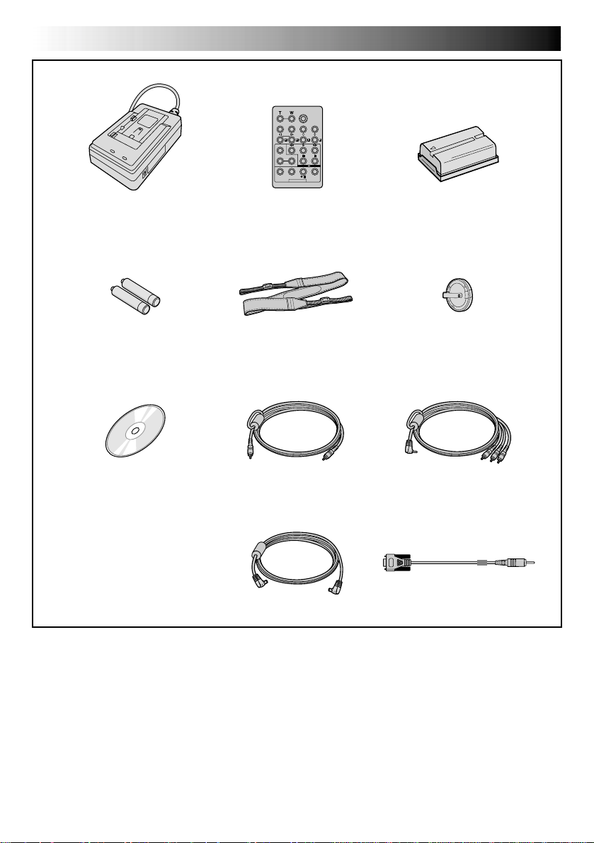
•AC Power Adapter/Charger
AA-V40U
•Remote Control Unit
RM-V716U
•DC Cord
•CD-ROM
The CD ROM contains the
following 7 software programs:
• JLIP Video Capture
• JLIP Video Producer
• Picture Navigator (for Windows
®
)
• Picture Navigator (for Macintosh
®
)
Presto!
• Mr. Photo
• PhotoAlbum
• ImageFolio
•AAA (R03) Battery x 2
(for remote control unit)
• PC Connection Cable
•Audio/Video Cable
(ø3.5 mini-plug to
RCA plug)
•Editing Cable
PROVIDED ACCESSORIES
•Shoulder Strap
•Battery Pack BN-V408U
• Lens Cap
EN7
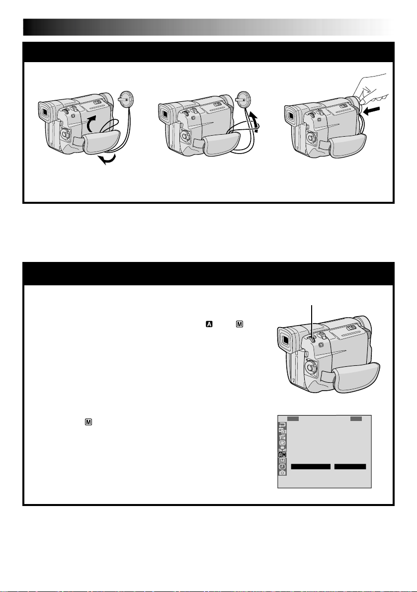
AUTOMATIC DEMONSTRATION
Automatic Demonstration takes place when “DEMO. MODE”
is set to “ON” (factory-preset).
Available when the Power Switch is set to “
” or “ ”
and no cassette is in the camcorder.
Performing any operation during the demonstration stops
the demonstration temporarily. If no operation is per-
formed for more than 1 minute after that, the demonstra-
tion will resume.
“DEMO. MODE” remains “ON” even if the camcorder
power is turned off.
To cancel Automatic Demonstration, set the Power
Switch to “
”, then press the MENU/BRIGHT wheel
while the demo is in progress. This takes you directly to
the demo mode’s Setting Menu (so you will not have to
go through the Menu Screen). Rotate the MENU/BRIGHT
wheel to select “OFF” and press it. The normal screen
appears.
1
R
S
Z
G
T
I
D
S
R
E
O
O
A
A
D
E
I
E
C
U
O
I
L
M
D
C
T
N
M
N
L
N
O
E
A
U
M
D
Y
U
.
M
R
O
U
M
M
L
E
N
D
M
P
B
O
E
R
E
O
E
D
D
A
D
R
E
E
ME
O
O
N
N
F
U
F
MENU/BRIGHT Wheel
12 3
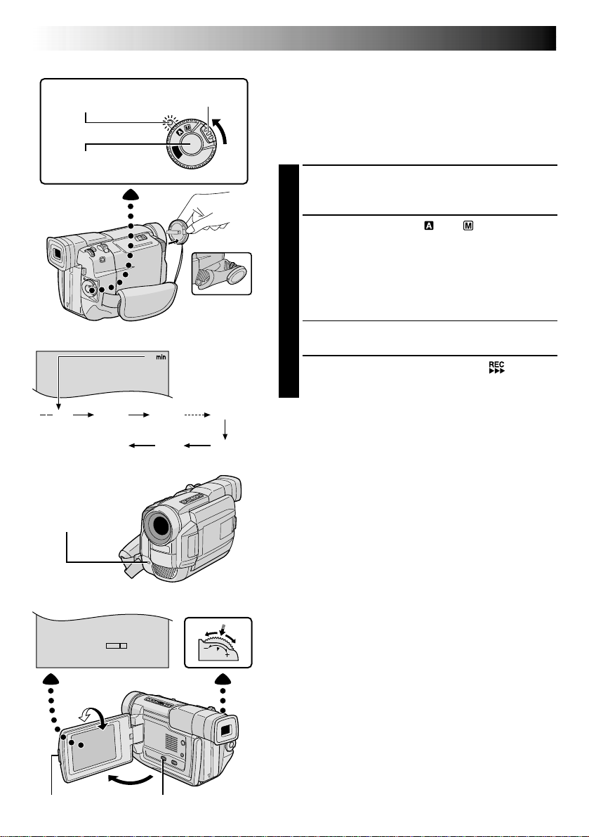
To protect the lens, attach the provided lens cap to the camcorder as shown in the illustration.
How To Attach The Lens Cap
8 EN
GETTING STARTED
Power
This camcorder’s 2-way power supply system lets you
choose the most appropriate source of power. Do not use
provided power supply units with other equipment.
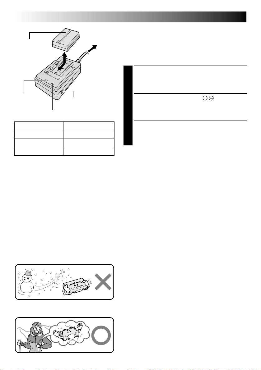
CHARGING THE BATTERY PACK
1
Make sure you unplug the camcorder’s DC cord from
the AC Power Adapter/Charger. Plug the AC Adapter/
Charger’s power cord into an AC outlet. The POWER
indicator lights.
2
Attach the battery pack with the mark aligned
with the corresponding marks on the AC Power
Adapter/Charger. The CHARGE Indicator begins
blinking to indicate charging has started.
3
When the CHARGE indicator stops blinking but stays
lit, charging is finished. Slide the battery and lift off.
Remember to unplug the AC Adapter/Charger’s
power cord from the AC outlet.
To AC outlet
CHARGE indicator
POWER
indicator
Battery pack
BN-V408U,
BN-V416U or
BN-V428U
DC OUT connector
AC Power
Adapter/Charger
NOTES:
●
If the protective cap is attached to the battery pack, remove it first.
●
Perform charging where the temperature is between 10°C and 35°C (50°F and 95°F). 20°C to 25°C (68°F to
77°F) is the ideal temperature range for charging. If the environment is too cold, charging may be incom-
plete.
●
Charging times noted above are for a fully discharged battery pack.
●
Charging time varies according to the ambient temperature and the status of the battery pack.
●
To avoid interference with reception, do not use the AC Power Adapter/Charger near a radio.
●
If you connect the camcorder’s DC cord to the adapter during battery charging, power is supplied to the
camcorder and charging stops.
●
Since the AC Power Adapter/Charger processes electricity internally, it becomes warm during use. Be sure to
use it only in well-ventilated areas.
●
When charging the battery pack for the first time or after a long storage period, the CHARGE indicator may
not light. In this case, remove the battery pack from the AC Power Adapter/Charger, then try charging again.
●
If the battery operation time remains extremely short even after having been fully charged, the battery is
worn out and needs to be replaced. Please purchase a new one.
Lithium-ion is vulnerable in colder
temperatures.
About Batteries
DANGER! Do not attempt to take the batteries apart, or
expose them to flame or excessive heat, as it may cause a fire
or explosion.
WARNING! Do not allow the battery or its terminals to come
in contact with metals, as this can result in a short circuit and
possibly start a fire.
The Benefits Of Lithium-Ion Batteries
Lithium-ion battery packs are small but have a large power
capacity. However, when one is exposed to cold temperatures
(below 10°C/50°F), its usage time becomes shorter and it may
cease to function. If this happens, place the battery pack in
your pocket or other warm, protected place for a short time,
then re-attach it to the camcorder. As long as the battery pack
itself is not cold, it should not affect performance.
(If you’re using a heating pad, make sure the battery pack does
not come in direct contact with it.)
Battery pack
BN-V408U
BN-V416U (optional)
BN-V428U (optional)
Fully charging time
approx. 1 hr. 30 min.
approx. 2 hrs.
approx. 3 hrs. 20 min.
EN9
1
3
2
To DC Input
connector
To DC OUT
connector
To AC outlet
AC Power
Adapter/Charger
DC cord
ATTENTION:
Before detaching the power source,
make sure that the camcorder’s power
is turned off. Failure to do so can result
in a camcorder malfunction.
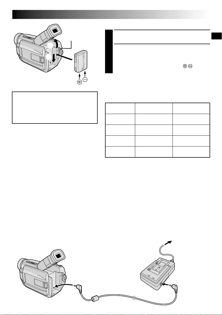
USING THE BATTERY PACK
1
Tilt the viewfinder upward 1.
2
With the arrow on the battery pack pointing
downward, push the battery pack slightly against the
battery pack mount 2, then slide down the battery
pack until it locks in place 3.
•If the battery pack is attached with its mark set
in the wrong direction, a malfunction may occur.
To Detach The Battery Pack. . .
.... tilt the viewfinder upward 1 and slide the battery
pack up slightly while pressing BATTERY RELEASE to
detach it.
Power cord
Approximate recording time
BATTERY RELEASE
Button
NOTES:
●
Recording time is reduced significantly under the
following conditions:
•
Zoom or Record-Standby mode is engaged repeatedly.
•
The LCD monitor is used repeatedly.
•
The playback mode is engaged repeatedly.
●
Before extended use, it is recommended that you
prepare enough battery packs to cover 3 times the
planned shooting time.
USING AC POWER
Use the AC Power Adapter/Charger (connect as shown in the illustration).
NOTES:
●
The provided AC Power Adapter/Charger features automatic voltage selection in the AC range from 110 V to
240 V.
●
For other notes,
pg. 8.
INFORMATION:
VU-V856KIT is a set composed of the
BN-V856U battery pack and AA-V80U AC
Power Adapter/Charger. Read the VU-V856KIT’s
instruction manuals before using.
It is impossible to charge the BN-V856U battery
pack using the provided AC Power Adapter/
Charger. Use the optional AA-V80U AC Power
Adapter/Charger.
( ) : when the video light is on.
Battery pack
BN-V408U
BN-V416U
(optional)
BN-V428U
(optional)
BN-V856U
(optional)
LCD monitor on/
Viewfinder off
1 hr.
(35 min.)
2 hrs.
(1hr. 10 min.)
3 hrs. 30 min.
(2 hrs.)
7 hrs.
(4 hrs.)
LCD monitor off/
Viewfinder on
1 hr. 15 min.
(40 min.)
2 hrs. 30 min.
(1 hr. 20 min.)
4 hrs. 20 min.
(2 hrs. 20 min.)
8 hrs. 40 min.
(4 hrs. 40 min.)
10 EN
3
1
2
PAUSE
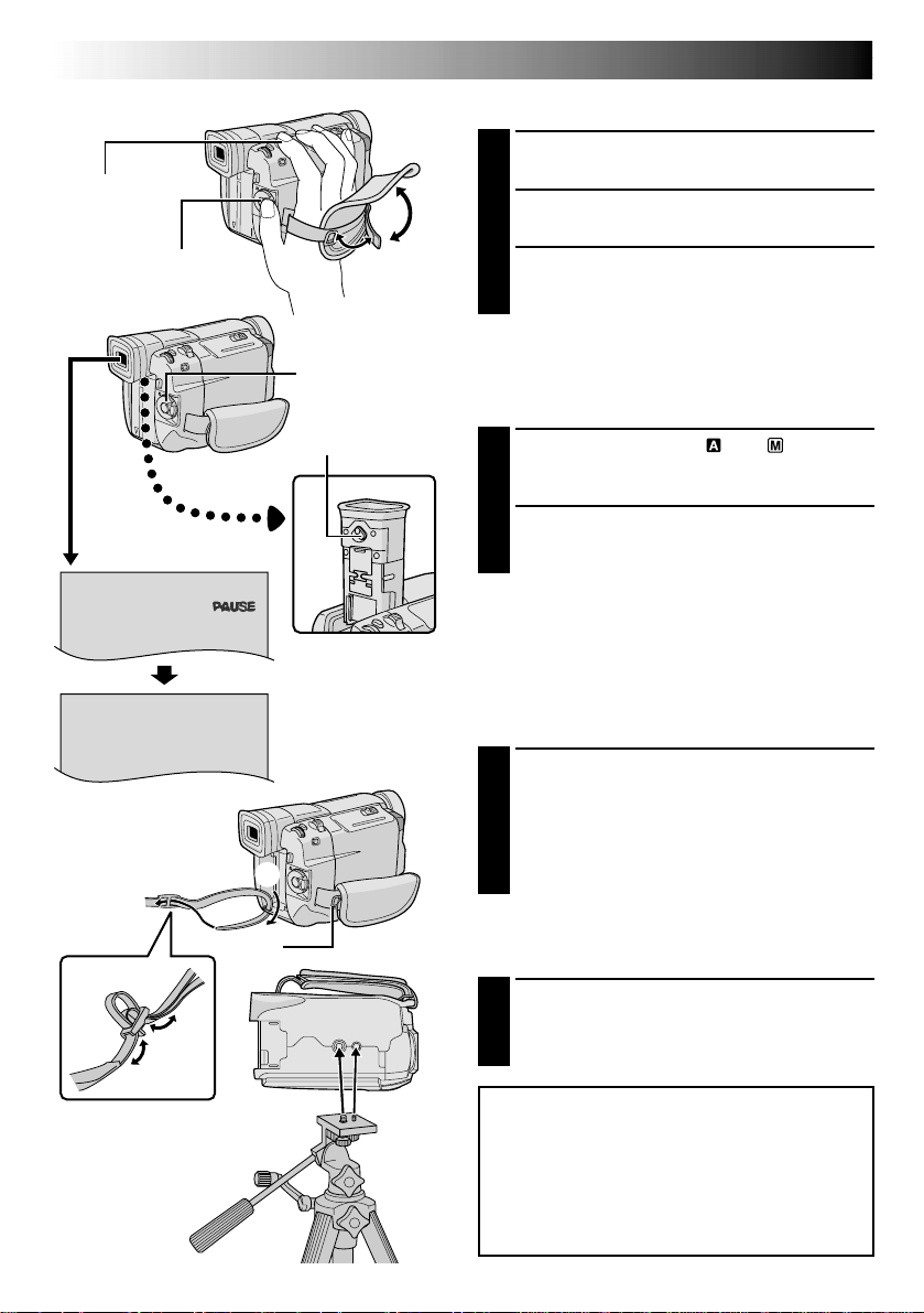
Grip Adjustment
1
Separate the Velcro strip.
2
Pass your right hand through the loop and grasp
the grip.
3
Adjust so that your thumb and fingers can easily
operate the Recording Start/Stop Button and
Power Zoom Lever. Refasten the Velcro strip.
Viewfinder Adjustment
1
1
Set the Power Switch to “ ” or “ ” while
pressing down the Lock Button located on the
switch.
2
Turn the Diopter Adjustment Control until the
indications in the viewfinder are clearly
focused.
Recording Start/Stop
button
Power Zoom
Lever
Diopter Adjustment
Control
Power Switch
GETTING STARTED
(cont.)
Shoulder Strap Attachment
1
Make sure the battery pack or DC cord is
removed. Following the illustration, thread the
strap through the eyelet 1, then fold it back and
thread it through the buckle 2. Repeat the
procedure to attach the other end of the strap to
the other eyelet 3 located under the Grip Strap ,
making sure the strap is not twisted.
CAUTION:
When using a tripod, be sure to open and
extend its legs fully to stabilize the
camcorder. To prevent damage to the unit
caused by falling over, do not use a small-
sized tripod.
Tripod Mounting
1
Align the screw and camera direction stud on
the tripod with the camera’s mounting socket
and stud hole. Then tighten the screw.
•Some tripods are not equipped with studs.
EN11
P
L
A
Y
O
F
F
4
FAD
W
W
R
O
F
F
F
E
I
I
A
F
A
A
A
R
P
P
N
F
D
D
D
/
E
E
D
E
E
E
W
–
–
O
R
R
R
I
S
S
M
–
–
–
P
C
H
W
B
M
E
R
U
H
L
O
O
T
I
A
S
L
T
T
C
A
L
E
E
K
I
R
C
1
O
D
T
C
R
N
A
I
L
D
E
T
M
O
I
T
S
E
E
C
S
U
C
/
K
P
R
R
T
C
L
N
E
I
O
A
A
E
M
D
D
Y
N
E
E
M
D
E
E
P
N
C
M
U
25
5
’
:
0
3
0
0
J.
Date/Time Settings
The date/time is recorded onto the tape at all times, but its
display can be turned on or off during playback
( pg. 34).
1
Set the Power Switch to “ ” while pressing down
the Lock Button located on the switch. The power
lamp lights and the camcorder is turned on.
2
Press the MENU/BRIGHT wheel. The Menu Screen
appears.
3
Rotate the MENU/BRIGHT wheel to select “ ”.
Press it and “DISPLAY MENU” appears.
4
Rotate the MENU/BRIGHT wheel to select “CLOCK
ADJ.”. Press it and “month” is highlighted.
Rotate the MENU/BRIGHT wheel to input the month.
Press it. Repeat to input the day, year, hour and
minute.
Rotate the MENU/BRIGHT wheel to select
“
1
RETURN”, and press it twice. The Menu Screen
closes.
NOTE:
Even if you select “CLOCK ADJ.”, if the parameter is not
highlighted the camcorder’s internal clock continues to
operate. Once you move the highlight bar to the first date/
time parameter (month), the clock stops. When you finish
setting the minute and press the MENU/BRIGHT wheel,
the date and time begin operation from the date and time
you just set.
Display
MENU/BRIGHT Wheel
Power Switch
Lock Button
DISPLAY MENU
Power lamp
12 EN
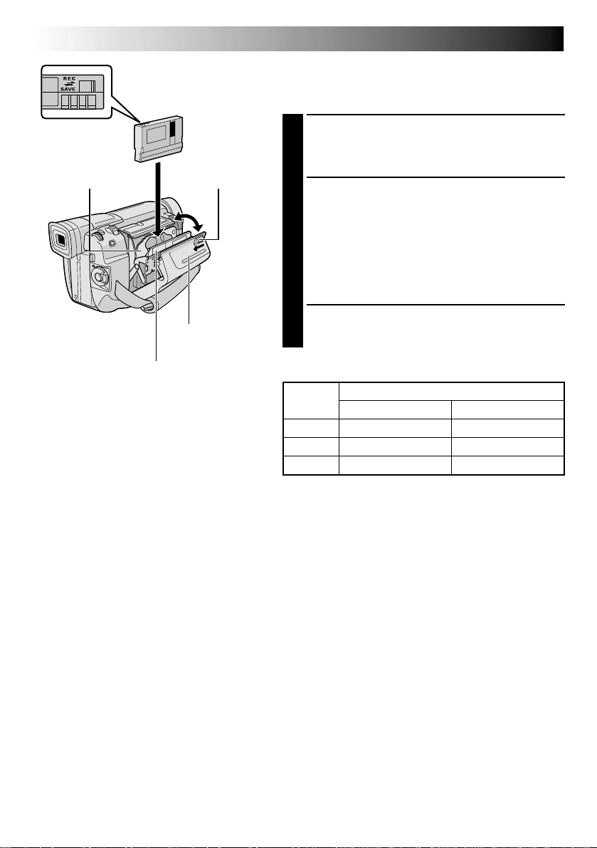
Loading/Unloading A Cassette
The camcorder needs to be powered up to load or eject a
cassette.
1
Slide and hold OPEN/EJECT in the direction of the
arrow then pull the cassette holder cover open until it
locks. The cassette holder opens automatically.
•Do not touch internal components.
2
Insert or remove a tape and press “PUSH HERE” to
close the cassette holder.
•Once the cassette holder is closed, it recedes
automatically. Wait until it recedes completely
before closing the cassette holder cover.
•When the battery’s charge is low, you may not be
able to close the cassette holder cover. Do not
apply force. Replace the battery with a fully charged
one before continuing.
3
Close the cassette holder cover firmly until it locks
into place.
OPEN/EJECT SwitchCassette holder
PUSH HERE
Cassette holder
cover
Make sure the
window side is
facing out.
Erase protection tab*
Tape
Recording mode
SP LP
30 min. 30 min. 45 min.
60 min. 60 min. 90 min.
80 min. 80 min. 120 min.
Approximate recording time
NOTES:
●
It takes a few seconds for the cassette holder to open. Do not apply force.
●
If you wait a few seconds and the cassette holder does not open, close the cassette holder cover and try
again. If the cassette holder still does not open, turn the camcorder off then on again.
●
If the tape does not load properly, open the cassette holder cover fully and remove the cassette. A few
minutes later, insert it again.
●
When the camcorder is suddenly moved from a cold place to a warm environment, wait a short time before
opening the cassette holder cover.
●
Closing the cassette holder cover before the cassette holder comes out may cause damage to the camcorder.
●
Even when the camcorder is switched off, a cassette can be loaded or unloaded. After the cassette holder is
closed with the camcorder switched off, however, it may not recede. It is recommended to turn the power on
before loading or unloading.
●
When resuming recording, once you open the cassette holder cover a blank portion will be recorded on the
tape or a previously recorded scene will be erased (recorded over) regardless of whether the cassette holder
came out or not. See page 21 for information about recording from the middle of a tape.
●
Loosen the Grip Strap if it appears to interfere with the cassette holder cover operation (
pg. 10).
*
To Protect Valuable Recordings . . .
.... slide the erase protection tab on the back of
the tape in the direction of “SAVE”. This
prevents the tape from being recorded over.
To record on this tape, slide the tab back to
“REC” before loading it.
GETTING STARTED
(cont.)
EN13
P
L
A
Y
O
F
F
1
R
S
Z
G
T
I
D
S
R
E
O
O
A
A
D
E
I
E
C
U
O
I
L
M
D
C
T
N
M
N
L
N
O
E
A
U
M
D
Y
U
.
M
R
O
U
M
M
L
E
N
D
M
P
B
O
E
R
E
O
E
D
D
A
D
R
E
E
MEN
S
L
U
P
P
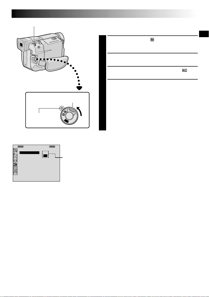
Recording Mode Setting
Set the tape recording mode depending on your preference.
1
Set the Power Switch to “ ” while pressing down
the Lock Button located on the switch. The power
lamp lights and the camcorder is turned on.
2
Press the MENU/BRIGHT wheel. The Menu Screen
appears.
3
Rotate the MENU/BRIGHT wheel to select “ ” and
press it. “CAMERA MENU” appears.
4
Rotate the MENU/BRIGHT wheel to select “REC
MODE” and press it. The Sub Menu appears. Select
“SP” or “LP” by rotating the MENU/BRIGHT wheel
and press it. Rotate the MENU/BRIGHT wheel to
select “
1
RETURN”, and press it twice. The Menu
Screen closes.
•Audio Dubbing ( pg. 60) and Insert Editing
( pg. 61) are impossible on a tape recorded in the
LP mode.
•“LP” (Long Play) is more economical, providing
1.5 times the recording time.
NOTES:
●
If the recording mode is switched during recording, the
playback picture will be blurred at the switching point.
●
It is recommended that tapes recorded in the LP mode
on this camcorder be played back on this camcorder.
●
During playback of a tape recorded on another
camcorder, blocks of noise may appear or there may be
momentary pauses in the sound.
Lock Button
Display
MENU/BRIGHT Wheel
Power Switch
Menu Screen
Sub Menu
Power lamp
14 EN
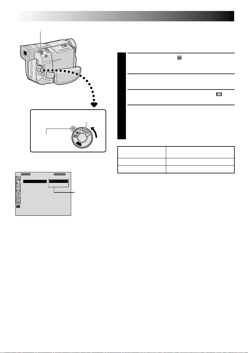
Approximate Number of
Storable Images
30
60
P
L
A
Y
O
F
F
1
Q
R
R
U
E
E
A
C
T
L
D
U
I
S
S
R
T
E
C
N
Y
LE
M
C
E
T
NU
S
F
T
I
A
N
N
E
DARD
Picture Quality Mode Setting
The Picture Quality mode can be selected to best match
your needs. Two Picture Quality modes are available:
FINE and STANDARD (in order of quality).
1
Set the Power Switch to “ ” while pressing down the
Lock Button located on the switch. The power lamp
lights and the camcorder is turned on.
2
Press the MENU/BRIGHT wheel. The Menu Screen
appears.
3
Rotate the MENU/BRIGHT wheel to select “ ” and
press it. “DSC MENU” appears.
4
Rotate the MENU/BRIGHT wheel to select
“QUALITY” and press it. The Sub Menu appears.
Rotate the MENU/BRIGHT wheel to select the
desired mode and press it. Rotate the MENU/BRIGHT
wheel to select “
1
RETURN”, and press it twice. The
Menu Screen closes.
Picture Quality Mode
FINE
STANDARD
Sub Menu
Display
MENU/BRIGHT Wheel
Power Switch
Lock Button
Menu Screen
Power lamp
GETTING STARTED
(cont.)
NOTES:
●
The number of storable images depends on the selected
Picture Quality mode as well as the composition of the
subjects in the images.
●
The numbers listed above are applicable when the
camcorder’s memory is empty (when there are no
sample images stored).
EN15
P
L
A
Y
O
F
F
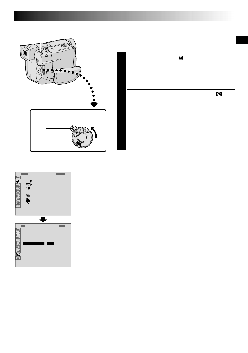
F. AUTO
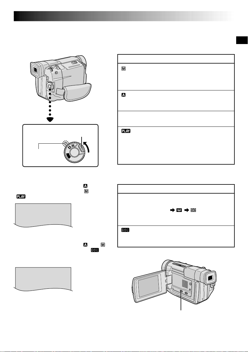
Operation Mode
Choose the appropriate operation mode according to your
preference using the Power Switch and VIDEO/DSC
Switch.
When the Power Switch is set to “ ”,
“F. AUTO” appears. When set to “ ” or
“ ”, there is no indication.
To turn on the camcorder, set the Power
Switch to any operation mode except
“OFF”while pressing down the Lock Button
located on the switch.
Power Switch
Lock Button
Power lamp
Power Switch Position
(Manual):
Allows you to set various recording functions using
the Menus. If you want more creative capabilities than
Full Auto recording, try this mode.
(Full Auto):
Allows you to record using NO special effects or
manual adjustments. Suitable for standard recording.
OFF:
Allows you to switch off the camcorder.
:
Allows you to play back a recording on the tape, to
display a still image stored in the camcorder’s built-in
memory or to transfer a still image recorded on the
tape or in the camcorder’s built-in memory to a
computer.
VIDEO/DSC Switch Position
VIDEO:
Allows you to record on a tape or play back a tape. If
“REC SELECT” is set to
“ / ”
in the DSC
Menu Screen, still images are also recorded in the
camcorder’s built-in memory.
:
Allows you to record a still image or display a still
image stored in the camcorder’s built-in memory.
VIDEO/DSC Switch (Open the
LCD monitor to access this switch.)
DSC
When the Power Switch is set to “ ” or “ ”
and the VIDEO/DSC Switch is set to “ ”,
“DSC” appears. When set to “VIDEO”, there is
no indication.
16 EN
25
90 min
89 min
3 min
2 min
1 min0 min
min
180°
90°
BR I GHT
–
+
P
L
A
Y
O
F
F
RECORDING
Basic Recording For Video
Power lamp
Tally lamp
(lights while recording
is in progress)
Lock Button
Recording
Start/Stop Button
Tape remaining
time indicator
(Approximate)
(Now calculating)
(Blinking) (Blinking) (Blinking)
Display
MENU/
BRIGHT Wheel
To Adjust The Brightness Of The Display
.... rotate the MENU/BRIGHT wheel until the bright level
indicator on the display moves and the appropriate
brightness is reached.
•If you are using the GR-DVL805, it is also possible to
adjust the brightness of the viewfinder by closing the
LCD monitor and adjusting as described above.
Power Switch
PUSH OPEN Button
NOTE:
You should already have performed the procedures listed
below. If not, do so before continuing.
●
Power (
pg. 8)
●
Grip Adjustment (
pg. 10)
●
Viewfinder Adjustment (
pg. 10)
●
Load A Cassette (
pg. 12)
●
Recording Mode Setting (
pg. 13)
1
Press in the tabs on the lens cap to remove it. Press
PUSH OPEN, open the LCD monitor and set the
VIDEO/DSC Switch to “VIDEO”.
2
Set the Power Switch to “ ” or “ ” while pressing
down the Lock Button located on the switch.
Shooting while using the LCD monitor:
Make sure
the LCD monitor is fully open. Tilt it upward/
downward for best viewability.
Shooting while using the viewfinder:
Close the LCD
monitor.
•The power lamp lights and the camcorder enters the
Record-Standby mode. “PAUSE” is displayed.
3
Press the Recording Start/Stop Button. “ ” appears
while recording is in progress.
To Stop Recording . . .
.... press the Recording Start/Stop Button. The camcorder
re-enters the Record-Standby mode.
During
shooting
VIDEO/DSC Switch
EN17
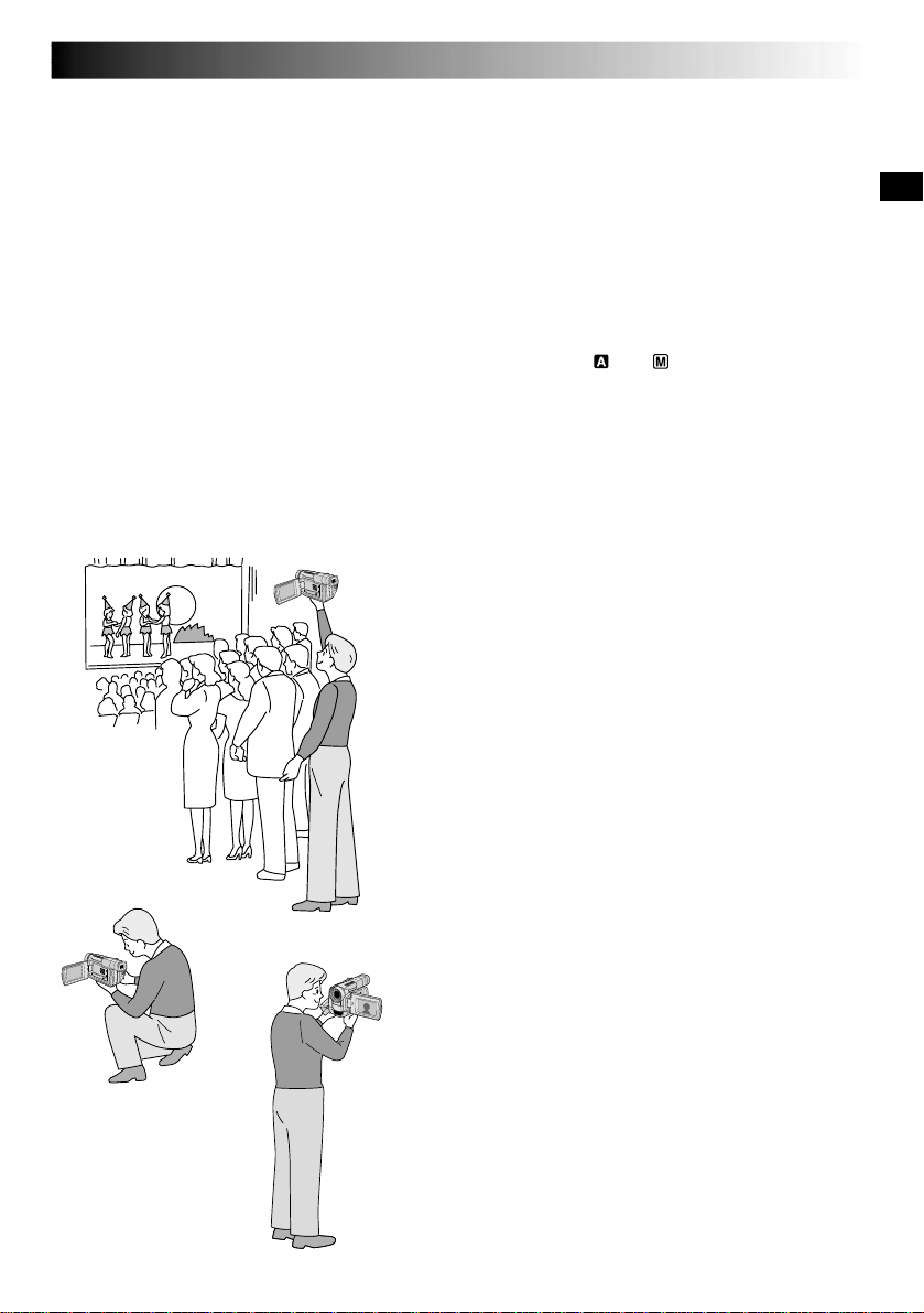
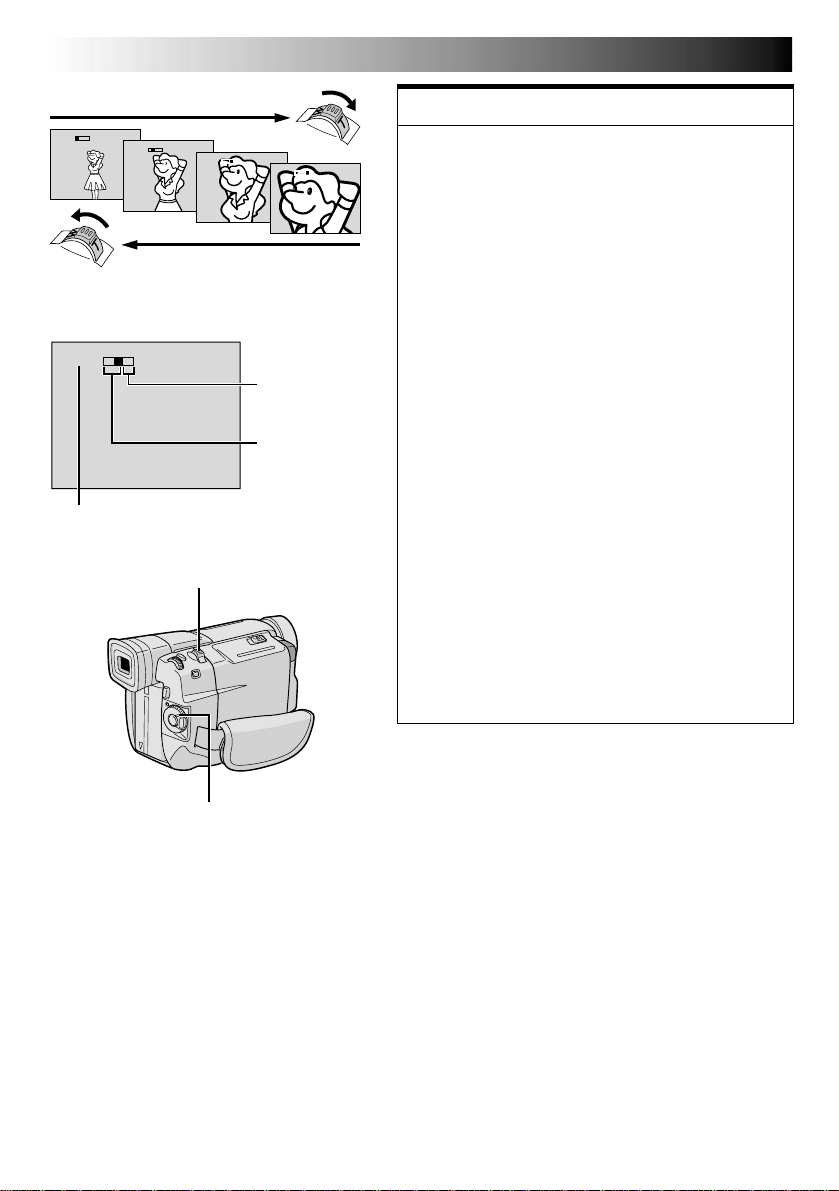
Self-Recording
JOURNALISTIC SHOOTING
In some situations, different shooting angles may provide
more dramatic results. Hold the camcorder in the desired
position and tilt the LCD monitor in the most convenient
direction. It can rotate 270° (90° downward, 180°
upward).
SELF-RECORDING
You can shoot yourself while viewing your own image in
the LCD monitor. Open the LCD monitor and tilt it upward
180° so that it faces forward, then point the lens toward
yourself and start recording.
NOTES:
●
When you use the LCD monitor outdoors in direct sunlight, the LCD monitor may be difficult to see. If this
happens, use the viewfinder instead.
●
The image will not appear simultaneously in the LCD monitor and the viewfinder .
●
The cassette holder cannot be opened unless a power supply is attached.
●
There may be a delay after you open the cassette holder cover until the cassette holder opens. Do not use force.
●
Once the cassette holder is closed, it recedes automatically. Wait until it recedes completely before closing
the cassette holder cover.
●
The time required to calculate and display the remaining tape length, and the accuracy of the calculation,
may vary according to the type of tape used.
●
“TAPE END” appears when the tape reaches its end, and the power goes off automatically if left in this
condition for 5 minutes. “TAPE END” also appears when a cassette at its end is loaded.
●
If the Record-Standby mode continues for 5 minutes, the camcorder’s power shuts off automatically. To turn
the camcorder on again, set the Power Switch to “OFF”, then back to “ ” or “ ”.
●
When a blank portion is left between recorded scenes on the tape, the time code is interrupted and errors
may occur when editing the tape. To avoid this, refer to “Recording from the middle of a tape” (
pg. 21).
●
During recording, sound is not heard from the speaker.
●
To turn the tally lamp off during recording,
pg. 24, 25.
●
To remove the indications from the camcorder’s display during recording,
pg. 24, 27.
18 EN
P
L
A
Y
O
F
F
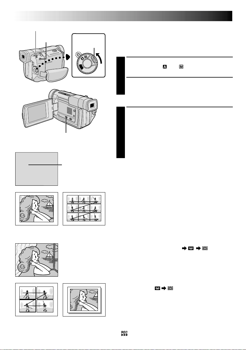
FULL
MULTI-9
Multi-Analyzer 9
FRAME
Snapshot mode with
frame*
FULL
Snapshot mode with no
frame*
MULTI-4
Multi-Analyzer 4
* There is the sound effect of a shutter closing.
RECORDING
Basic Recording For Video (cont.)
Snapshot (For Video Recording)
This feature lets you record still images that look like
photographs onto a tape.
SNAPSHOT MODE SELECTION
1
Set the VIDEO/DSC Switch to “VIDEO”, then set the
Power Switch to “ ” or “ ” while pressing down
the Lock Button located on the switch.
2
Choose the appropriate Snapshot mode from the 5
available by repeatedly pressing MODE until the
desired snapshot mode indicator appears.
SNAPSHOT RECORDING
1
Press SNAPSHOT.
If you press during Record-Standby . . .
.... “PHOTO” appears and a still image will be
recorded for approx. 6 seconds, then the
camcorder re-enters the Record-Standby mode.
If you press during Recording . . .
.... “PHOTO” appears and a still image will be
recorded for approx. 6 seconds, then the normal
recording resumes.
Motor Drive Mode
Keeping SNAPSHOT pressed provides an effect similar to
serial photography. (Interval between still images: approx.
1 second)
NOTES:
●
Even if “MULTI-4” or “MULTI-9” is engaged, Snapshot
recording will be performed in the FULL mode during
Digital Zoom.
●
If Snapshot recording is not possible, “PHOTO” blinks
when SNAPSHOT is pressed.
●
If Program AE with special effects (
pg. 30) is
engaged, certain modes of Program AE with special
effects are disabled during Snapshot recording. In such a
case, the icon blinks.
●
If SNAPSHOT is pressed when “DIS” is set to “ON”
(
pg. 26), the Stabilizer will be disabled.
●
When “REC SELECT” is set to “ / ” in the
Menu Screen (
pg. 27), still images are recorded not
only onto the tape but also in the camcorder’s built-in
memory. If SNAPSHOT is pressed when a tape is not
loaded, still images will not be recorded in the memory.
●
To dub images recorded on a tape to the camcorder’s
built-in memory,
pg. 49.
●
During tape playback as well, all snapshot modes are
available when “ COPY” is set to “OFF” in the
Menu Screen (
pg. 34). However, the shutter sound is
not heard.
●
During Snapshot recording, the image displayed in the
viewfinder may be partially missing. However, there is
no effect in the recorded image.
●
When a cable is connected to the AV connector, the
shutter sound is not heard from the speaker, however it
is recorded onto the tape.
●
will appear while the snapshot is being taken.
Power Switch
SNAPSHOT Button
Lock Button
MODE Button
VIDEO/DSC Switch (Open the
LCD monitor to access this switch.)
PIN-UP
Pin-Up mode*
Snapshot mode
EN19
P
L
A
Y
O
F
F
RECORDING
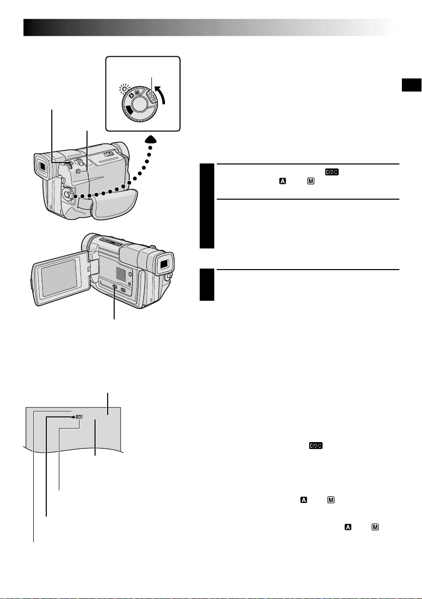
Basic Recording For Digital Still Camera (D.S.C.)
Basic Shooting (Snapshot)
You can use your camcorder as a Digital Still Camera for
taking snapshots.
NOTE:
You should already have performed the procedures listed
below. If not, do so before continuing.
●
Power (
pg. 8)
●
Grip Adjustment (
pg. 10)
●
Viewfinder Adjustment (
pg. 10)
●
Picture Quality Mode Setting (
pg. 14)
SNAPSHOT MODE SELECTION
1
Set the VIDEO/DSC Switch to “ ”, then set the
Power Switch to “ ” or “ ” while pressing down
the Lock Button located on the switch.
2
Choose the appropriate Snapshot mode from the 5
available by repeatedly pressing MODE until the
desired snapshot mode indicator appears.
•The available Snapshot modes are the same as
those on pg. 18.
SNAPSHOT RECORDING
1
Press SNAPSHOT.
The image is stored in the camcorder’s built-in
memory.
To Delete Unwanted Still Images . . .
.... when unwanted still images are stored in the
camcorder’s built-in memory or its memory is full,
refer to “Deleting Images” ( pg. 40) and delete
unwanted still images.
NOTES:
●
Even if “MULTI-4” or “MULTI-9” is engaged, Snapshot
recording will be performed in the FULL mode during
Digital Zoom.
●
Even if “DIS” is set to “ON” (
pg. 26), the Stabilizer
will be disabled.
●
If Snapshot recording is not possible, “PHOTO” blinks
when SNAPSHOT is pressed.
●
The Motor Drive mode (
pg. 18) is disabled when the
VIDEO/DSC Switch is set to “ ”.
●
If Program AE with special effects (
pg. 30) is
engaged, certain modes of Program AE with special
effects are disabled during Snapshot recording. In such a
case, the icon blinks.
●
If shooting is not performed for approx. 5 minutes when
the Power Switch is set to “ ” or “ ” and power is
supplied from the battery pack, the camcorder shuts off
automatically to save power. To perform shooting again,
set the Power Switch to “OFF”, then to “ ” or “ ”.
●
Some sample images have been stored in the built-in
memory at the factory. If you wish to delete them, first
remove the “Protect” function (
pg. 39), then perform
the “Delete” function (
pg. 40).
Power Switch
SNAPSHOT Button
Lock Button
VIDEO/DSC Switch (Open the
LCD monitor to access this switch.)
MODE
Button
STD
10 / 30
Number of shots taken
Displays the number of images that
have already been shot.
Total number of shots
Displays the approximate total number of shots that
can be stored, including those already taken. The
number increases or decreases depending on the shots
stored, the Picture Quality mode, etc.
Picture Quality mode
Displays the Picture Quality mode of the stored
image. There are 2 modes available:
FINE and STD (Standard) (
pg. 14).
Memory icon
Appears during shooting.
Display
Shooting icon
Appears and blinks during shooting.
20 EN
10
x
W
T
1
x
W
T
10
x
W
T
20
x
W
T
40
x
W
T
RECORDING
Basic Recording For Video And D.S.C.
Zoom in (T: Telephoto)
Zoom out (W: Wide angle)
Power Zoom Lever
Zoom display
FEATURE:
Zooming
PURPOSE:
To produce the zoom in/out effect, or an instantaneous
change in image magnification.
OPERATION:
Zoom In
Slide the Power Zoom Lever towards “T”.
Zoom Out
Slide the Power Zoom Lever towards “W”.
The further you slide the Power Zoom Lever, the
quicker the zoom action.
NOTES:
●
Focusing may become unstable during Zooming. In
this case, set the zoom while in Record-Standby,
lock the focus by using the manual focus
(
pg. 23), then zoom in or out in Record mode.
●
Zooming is possible to a maximum of 250X, or it
can be switched to 10X magnification using the
optical zoom (
pg. 25).
●
Zoom magnification of over 10X is done through
Digital image processing, and is therefore called
Digital Zoom.
●
During Digital zoom, the quality of image may
suffer.
●
Digital zoom cannot be used
w
hen digital image
processing, such as Picture Wipe/Dissolve
(
pg. 28, 29) or Video Echo (
pg. 30), is
activated.
●
Macro shooting (as close as approx. 5 cm (2") to the
subject) is possible when the Power Zoom Lever is
set all the way to “W”. Also see “TELE MACRO” in
the Menu Screen on page 26.
Approximate zoom ratio
Digital zoom
zone
10X (optical)
zoom zone
Power Switch
EN21
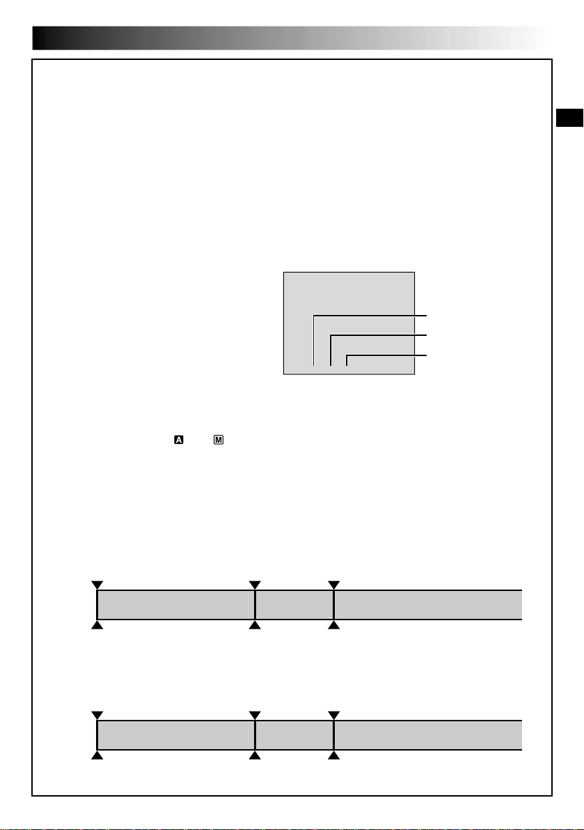
NOTE: Recording From The Middle Of A Tape
Time Code
During recording, a time code is recorded on the tape. This code is to confirm the location of the recorded
scene on the tape during playback.
If recording starts from a blank portion, the time code begins counting from “00:00:00”
(minute:second:frame). If recording starts from the end of a previously recorded scene, the time code
continues from the last time code number.
To perform Random Assemble Editing ( pg. 54 – 59), time code is necessary. If during recording a blank
portion is left partway through the tape, the time code is interrupted. When recording is resumed, the time
code starts counting up again from “00:00:00”. This means the camcorder may record the same time
codes as those existing in a previously recorded scene. To prevent this, perform “Recording From The
Middle of A Tape” below in the following cases;
•When shooting again after playing back a
recorded tape.
•When power shuts off during shooting.
•When a tape is removed and re-inserted during
shooting.
•When shooting using a partially recorded tape.
•When shooting on a blank portion located
partway through the tape.
•When shooting again after shooting a scene
then opening/closing the cassette holder cover.
Recording From The Middle Of A Tape
1. Play back a tape to find the spot at which you want to start recording, then engage the Still Playback
mode ( pg. 33).
2. Set the Power Switch to “ ” or “ ” while pressing down the Lock Button located on the switch, then
start recording.
NOTES:
●
The time code cannot be reset.
●
During fast-forwarding and rewinding, the time code indication does not move smoothly.
●
The time code is displayed only when “TIME CODE” is set to “ON” (
pg. 27, 34).
Shooting start point
Newly recorded sceneBlankAlready recorded scene
Time code
05:43:21
Time code
00:00:00
Tape
Time code
00:00:00
Shooting start pointShooting stop point
TC
12
:
34
:
24
Display
When a blank portion is recorded on a tape
Shooting start point
Time code
05:43:21
Time code
05:44:00
Tape
Time code
00:00:00
Shooting start pointShooting start point
Proper recording
Latest sceneNew sceneAlready recorded scene
Frames
(30 frames = 1 second)
Seconds
Minutes
Frames are not displayed
during recording.
22 EN
RECORDING
Basic Recording For Video And D.S.C. (cont.)
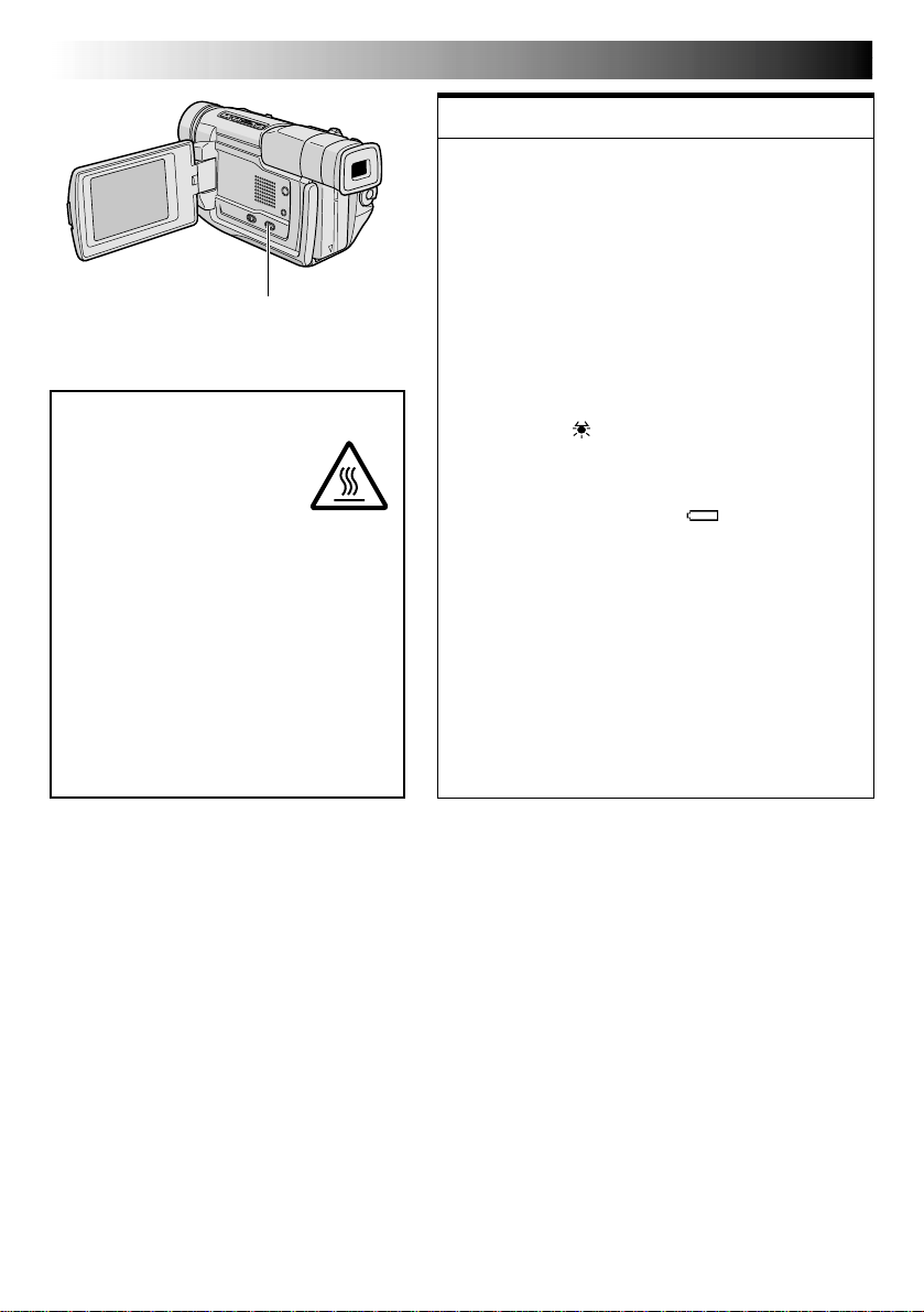
DANGER
The video light can become
extremely hot. Do not touch
it either while in operation or
soon after turning it off,
otherwise serious injury may
result.
Do not place the camcorder into the
carrying case immediately after using the
video light, since it remains extremely
hot for some time.
When operating, keep a distance of
about 30 cm (11-13/16") between the
video light and people or objects.
Do not use near flammable or explosive
materials.
It is recommended that you consult your
nearest JVC dealer for replacing the video
light.
LIGHT OFF/AUTO/ON Switch
(Open the LCD monitor to
access this switch.)
FEATURE:
Video Light
PURPOSE:
To brighten the scene when natural lighting is too dim.
OPERATION:
Set LIGHT OFF/AUTO/ON as required:
OFF : Turns off the light.
AUTO : Automatically turns on the light when the
camcorder senses insufficient lighting on the
subject.
ON : Always keeps the light on as long as the
camcorder is turned on.
The video light can only be used with the
camcorder’s power on.
It is recommended to set the white balance
( pg. 32) to when you use the video light.
When not using the video light, turn it off to save
battery power.
NOTES:
●
Even if the battery indicator ( ) does not blink
due to low battery charge, the camcorder may turn
off automatically when you turn on the video light,
or when you start recording with the video light
turned on.
●
When LIGHT OFF/AUTO/ON is set to “AUTO”:
•
Depending on the lighting conditions, the video
light may keep turning on and off. In this case,
manually switch the light on or off using LIGHT
OFF/AUTO/ON.
•
While the “SHUTTER” mode (
pg. 30) is
engaged, the light is likely to stay on.
•
While the “TWILIGHT” mode (
pg. 30) is
engaged, the light will not activate.
EN23
While focusing on a nearer
subject
While focusing on a further
subject
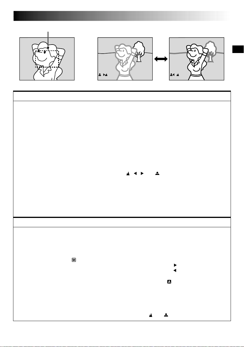
FEATURE:
Auto Focus
PURPOSE:
The camcorder’s Full Range AF system offers continuous shooting ability from close-up (as close as approx.
5 cm (2") to the subject) to infinity.
However, correct focus may not be obtainable in the situations listed below (in these cases use manual
focusing):
•When two subjects overlap in the same scene.
•When illumination is low.*
•When the subject has no contrast (difference in brightness and darkness), such as a flat, one-color wall, or
a clear, blue sky.*
•When a dark object is barely visible in the viewfinder.*
•When the scene contains minute patterns or identical patterns that are regularly repeated.
•When the scene is affected by sunbeams or light reflecting off the surface of a body of water.
•When shooting a scene with a high-contrast background.
* The following low-contrast warnings appear blinking: , , and
NOTES:
●
If the lens is smeared or blurred, accurate focusing is not possible. Keep the lens clean, wiping with a
piece of soft cloth if it gets dirty. When condensation occurs, wipe with a soft cloth or wait for it to dry
naturally.
●
When shooting a subject close to the lens, zoom out first (
pg. 20). If zoomed-in in the auto focus
mode, the camcorder may automatically zoom out depending on the distance between the camcorder
and the subject. This will not occur when “TELE MACRO” (
pg. 26) is activated.
FEATURE:
Manual Focus
PURPOSE:
To obtain correct focus.
OPERATION:
1) If you are using the viewfinder, you should already have made the necessary viewfinder adjustments
( pg. 10).
2) Set the Power Switch to “ ”, then press FOCUS (
3
). The manual focus indicator appears.
3) To focus on a farther subject, rotate the MENU/BRIGHT wheel towards “+”. “ ” appears and blinks.
To focus on a nearer subject, rotate the MENU/BRIGHT wheel towards “–”. “ ” appears and blinks.
4) Press the MENU/BRIGHT wheel. Focus adjustment is complete.
To reset to Auto Focus, press FOCUS (
3
) twice or set the Power Switch to “ ”.
If FOCUS (
3
) is pressed once, the camcorder will enter the focus adjustment mode again.
NOTES:
●
Be sure to focus the lens in the maximum telephoto position when you use the Manual Focus mode. If
you focus in on a subject in the wide-angle position, sharply focused images cannot be obtained when
zoomed up because the depth-of-field is reduced at longer focal lengths.
●
When the focus level cannot be adjusted any further or closer, “ ” or “ ” will blink.
Focus detection zone
RECORDING
Advanced Features For Video And D.S.C.
24 EN
END
1
R
S
Z
G
T
I
D
S
R
E
O
O
A
A
D
E
I
E
C
U
O
I
L
M
D
C
T
N
M
N
L
N
O
E
A
U
M
D
Y
U
.
M
R
O
U
M
M
L
E
N
D
M
P
B
O
E
R
E
O
E
D
D
A
D
R
E
E
MEN
S
L
U
P
P
1
D
T
W
W
C
R
I
E
I
I
A
E
S
L
D
N
M
M
T
E
E
D
A
U
R
N
R
M
M
C
E
U
N
A
O
U
S
A
C
D
T
E
L
R
E
T
O
ME
O
O
N
N
F
U
F
1
O
D
T
C
R
N
A
I
L
D
E
T
M
O
I
T
S
E
E
C
S
U
C
/
K
P
R
R
T
C
L
N
E
I
O
A
A
E
M
D
D
Y
N
E
E
M
D
E
E
P
N
C
M
U
25
5
’
:
0
3
0
0
J.
4
FAD
W
W
R
O
F
F
F
E
I
I
A
F
A
A
A
R
P
P
N
F
D
D
D
/
E
E
D
E
E
E
W
–
–
O
R
R
R
I
S
S
M
–
–
–
P
C
H
W
B
M
E
R
U
H
L
O
O
T
I
A
S
L
T
T
C
A
L
E
E
K
I
R
C
1
Q
R
R
U
E
E
A
C
T
L
D
U
I
S
S
R
T
E
C
N
Y
LE
M
C
E
T
NU
S
F
T
I
A
N
N
E
DARD
P
L
A
Y
O
F
F
Display
Menu Screen
MENU/BRIGHT Wheel
Lock Button
Power Switch
RECORDING
Advanced Features For Video And D.S.C. (cont.)
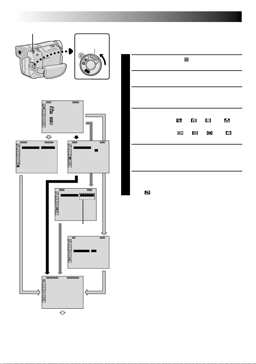
Using Menus For Detailed Adjustment
This camcorder is equipped with an easy-to-use,
on-screen menu system that simplifies many of the more
detailed camcorder settings ( pg. 25 – 27) .
1
Set the Power Switch to “ ” while pressing down
the Lock Button located on the switch.
2
Press the MENU/BRIGHT wheel. The Menu Screen
appears.
3
Rotate the MENU/BRIGHT wheel to select the
desired function icon, and press it. The selected
function menu appears.
4
Function menu setting depends on the function.
If you have selected “ ”, “ ”, “ ” or “ ” . . .
.... see pg. 25.
If you have selected “ ”, “ ”, “ ” or “ ” . . .
.... go to step 5.
5
Rotate the MENU/BRIGHT wheel to select the
desired function and press it. The Sub Menu appears.
Then, rotate the MENU/BRIGHT wheel to select the
parameter, and press it. Selection is complete.
6
Rotate the MENU/BRIGHT wheel to select
“
1
RETURN” and press it twice. The Menu Screen
closes.
•The icon represents “END”.
Sub Menu
Normal Screen
EN25
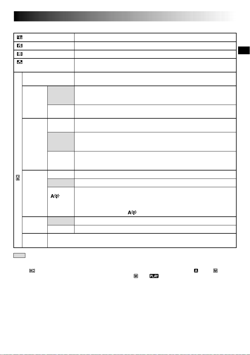
Menu Screen Explanations
: Factory-preset
Refer to “Fade/Wipe Effects” ( pg. 28, 29).
Refer to “Program AE With Special Effects” ( pg. 30).
Refer to “Exposure Control” and “Iris Lock” ( pg. 31).
Refer to “White Balance Adjustment” and “Manual White Balance Operation”
( pg. 32).
Allows you to set the video recording mode (SP or LP) depending on your
preference ( pg. 13).
Enables video recording of stereo sound on four separate channels, and is
recommended for use when performing audio dubbing ( pg. 60).
(Equivalent to the 32 kHz mode of previous models)
Enables video recording of stereo sound on two separate channels. (Equiva-
lent to the 48 kHz mode of previous models)
When set to “10X” while using digital zoom, the zoom magnification will
reset to 10X since digital zoom will be disengaged.
Allows you to use the Digital Zoom. By digitally processing and magnifying
images, zooming is possible from 10X (the optical zoom limit), to a maximum
of 40X digital magnification.
Allows you to use the Digital Zoom. By digitally processing and magnifying
images, zooming is possible from 10X (the optical zoom limit), to a maximum
of 250X digital magnification.
Allows you to shoot dark scenes with no picture brightness adjustment.
The overall appearance may be grainy, but the image is bright.
The shutter speed is automatically adjusted (1/30 — 1/200 sec.). Shooting a
subject in low or poor lighting at 1/30 sec. shutter speed provides a brighter
image than in the AGC mode, but the subject’s movements are not smooth or
natural. The overall appearance may be grainy. When the shutter speed is
automatically adjusted, “ ” is displayed.
The tally lamp comes on to signal the start of recording.
The tally lamp remains off at all times.
This number is necessary when connecting the camcorder to a device such as a computer
using the J terminal (JLIP). The numbers range from 01 to 99. Factory setting is 06.
CONTINUED ON NEXT PAGE
CAMERA MENU
FADER/WIPE
P.AE/EFFECT
EXPOSURE
W.BALANCE
REC MODE
SOUND
MODE
ZOOM
GAIN UP
TALLY
ID
NUMBER
12 BIT
16 BIT
10X
40X
250X
OFF
AGC
AUTO
ON
OFF
NOTES:
●
The “ CAMERA MENU” settings are effective when the Power Switch is set to both “ ” and “ ”.
●
“REC MODE” can be set when the Power Switch is set to “ ” or “ ” (
pg. 13, 34).
26 EN
: Factory-preset
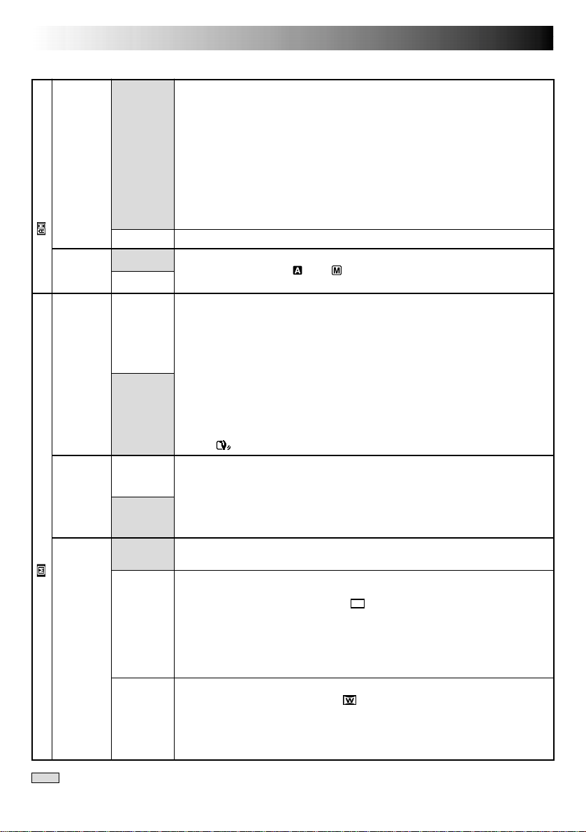
Menu Screen Explanations (cont.)
RECORDING
Advanced Features For Video And D.S.C. (cont.)
DIS
TELE
MACRO
WIDE
MODE
MANUAL MENU
DEMO.
MODE
CAMERA MENU
Demonstrates certain functions such as Program AE with special effects, etc.,
and can be used to confirm how these functions operate. When “DEMO.
MODE” is set to “ON” and the Menu Screen is closed, demonstration starts.
Performing any operation during the demonstration stops the demonstration
temporarily. If no operation is performed for more than 1 minute after that,
the demonstration will resume.
NOTES:
● If a tape is in the camcorder, the demonstration cannot be turned on.
● “DEMO. MODE” remains “ON” even if the camcorder power is turned off.
● If “DEMO. MODE” remains “ON”, some functions will not be available.
After viewing demo, set to “OFF”.
Automatic demonstration will not take place.
The Side LED indicator ( p. 74, 75) lights on the camcorder when the
Power Switch is set to “ ” or “ ”.
To compensate for unstable images caused by camera-shake, particularly at
high magnification.
NOTES:
● Accurate stabilization may not be possible if hand shake is excessive, or
under the following conditions:
•When shooting subjects with vertical or horizontal stripes.
•When shooting dark or dim subjects.
•When shooting subjects with excessive backlighting.
•When shooting scenes with movement in various directions.
•When shooting scenes with low-contrast backgrounds.
● Switch off this mode when recording with the camcorder on a tripod.
● The “ ” indicator blinks or goes out if the Stabilizer cannot be used.
Usually the distance to a subject where the lens is in focus depends on the
zoom magnification. Unless there is a distance more than 1m (3.3 ft.) to the
subject, the lens is out of focus at the maximum telephoto setting. When set
to “ON”, you can shoot a subject as large as possible at a distance of approx.
60 cm (2 ft.).
•Depending on the zoom position, the lens may go out of focus.
Records with no change in the screen ratio. For playback on a TV with a
normal screen ratio.
Inserts black bands at the top and bottom of the screen. During playback on
wide-screen TVs, the black bands at the top and bottom of the screen are cut
and the screen ratio becomes 16:9. appears. When using this mode, refer
to your wide-screen TV’s instruction manual. During playback/recording on
4:3 TVs/LCD monitor/viewfinder, black bands are inserted at the top and
bottom of the screen and the image appears like a letterboxed 16:9 movie.
•The “CINEMA” mode is effective only when the VIDEO/DSC Switch is set
to “VIDEO”.
For playback on TVs with an aspect ratio of 16:9. Naturally expands the image
to fit the screen without distortion. appears. When using this mode, refer to
your wide-screen TV’s instruction manual. During playback/recording on 4:3
TVs/LCD monitor/viewfinder, the image is elongated vertically.
•The “SQUEEZE” mode is effective only when the VIDEO/DSC Switch is set
to “VIDEO”.
ON
OFF
ON
OFF
ON
OFF
ON
OFF
OFF
CINEMA
SQUEEZE
SIDE LED
 Loading...