


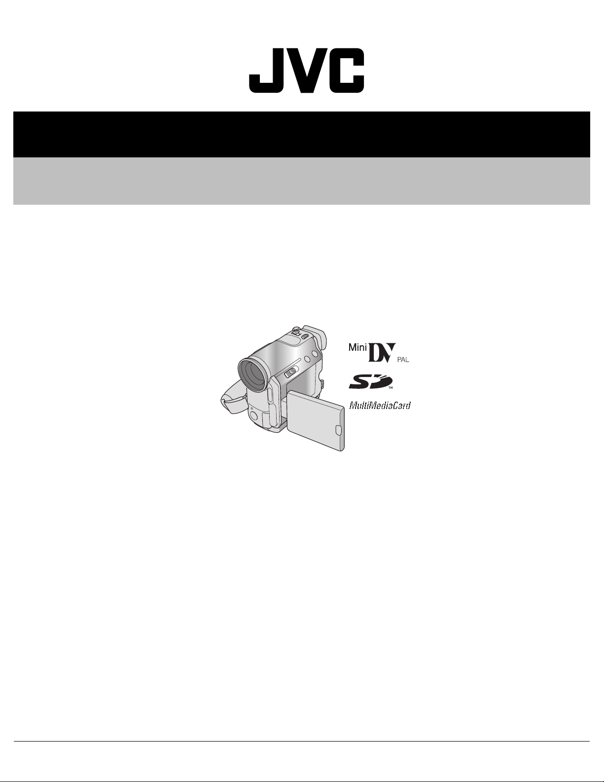
GR-DZ7AC
Table of contents
 Loading...
JVC GR-DZ7AC, GR-DZ7AG, GR-DZ7AH, GR-DZ7AS, GR-DZ7EK Service Manual
...
SERVICE MANUAL
DIGITAL VIDEO CAMERA
YF05720048
GR-DZ7AC, GR-DZ7AG, GR-DZ7AH,
GR-DZ7AS, GR-DZ7EK, GR-DZ7EX,
GR-DZ7EY, GR-DZ7EZ
GR-DZ7AC, GR-DZ7AG, GR-DZ7AH, GR-DZ7AS, GR-DZ7EK,
GR-DZ7EX, GR-DZ7EY, GR-DZ7EZ[M4D6S5]
For disassembling and assembling of MECHANISM ASSEMBLY, refer to the SERVICE MANUAL No.86700(MECHANISM ASSEMBLY).
TABLE OF CONTENTS
1 PRECAUTIONS . . . . . . . . . . . . . . . . . . . . . . . . . . . . . . . . . . . . . . . . . . . . . . . . . . . . . . . . . . . . . . . . . . . . . . . 1-3
2 SPECIFIC SERVICE INSTRUCTIONS . . . . . . . . . . . . . . . . . . . . . . . . . . . . . . . . . . . . . . . . . . . . . . . . . . . . . . 1-5
3 DISASSEMBLY . . . . . . . . . . . . . . . . . . . . . . . . . . . . . . . . . . . . . . . . . . . . . . . . . . . . . . . . . . . . . . . . . . . . . . . 1-6
4 ADJUSTMENT . . . . . . . . . . . . . . . . . . . . . . . . . . . . . . . . . . . . . . . . . . . . . . . . . . . . . . . . . . . . . . . . . . . . . . . 1-20
5 TROUBLE SHOOTING. . . . . . . . . . . . . . . . . . . . . . . . . . . . . . . . . . . . . . . . . . . . . . . . . . . . . . . . . . . . . . . . . 1-24
COPYRIGHT © 2004 Victor Company of Japan, Limited
No.YF057
2004/8
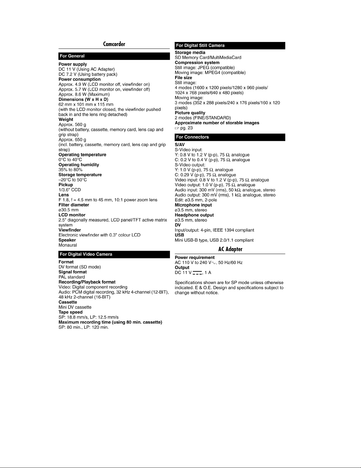
SPECIFICATION (The specifications shown pertain specifically to the model GR-DZ7EK)
1-2 (No.YF057)
SECTION 1
r
e
PRECAUTIONS
1.1 SAFTY PRECAUTIONS
Prior to shipment from the factory, JVC products are strictly
inspected to conform with the recognized product safety and
electrical codes of the countries in which they are to be
sold.However,in order to maintain such compliance, it is equally
important to implement the following precautions when a set is
being serviced.
1.1.1 Precautions during Servicing
(1) Locations requiring special caution are denoted by labels
and inscriptions on the cabinet, chassis and certain parts of
the product.When performing service, be sure to read and
comply with these and other cautionary notices appearing
in the operation and service manuals.
(2) Parts identified by the symbol and shaded ( ) parts
are critical for safety.
Replace only with specified part numbers.
NOTE :
Parts in this category also include those specified to
comply with X-ray emission standards for products
using cathode ray tubes and those specified for
compliance with various regulations regarding
spurious radiation emission.
(3) Fuse replacement caution notice.
Caution for continued protection against fire hazard.
Replace only with same type and rated fuse(s) as
specified.
(4) Use specified internal wiring. Note especially:
• Wires covered with PVC tubing
• Double insulated wires
• High voltage leads
(5) Use specified insulating materials for hazardous live parts.
Note especially:
• Insulation Tape
• PVC tubing
•Spacers
• Insulation sheets for transistors
•Barrier
(6) When replacing AC primary side components (transformers,
power cords, noise blocking capacitors, etc.) wrap ends of
wires securely about the terminals before soldering.
emission. Consequently, when servicing these products,
replace the cathode ray tubes and other parts with only the
specified parts. Under no circumstances attempt to modify
these circuits.Unauthorized modification can increase the
high voltage value and cause X-ray emission from the
cathode ray tube.
(12) Crimp type wire connectorIn such cases as when replacing
the power transformer in sets where the connections
between the power cord and power trans former primary
lead wires are performed using crimp type connectors, if
replacing the connectors is unavoidable, in order to prevent
safety hazards, perform carefully and precisely according
to the following steps.
• Connector part number :E03830-001
• Required tool : Connector crimping tool of the proper
type which will not damage insulated parts.
• Replacement procedure
a) Remove the old connector by cutting the wires at a
point close to the connector.Important : Do not
reuse a connector (discard it).
cut close to connector
Fig.1-1-3
b) Strip about 15 mm of the insulation from the ends
of the wires. If the wires are stranded, twist the
strands to avoid frayed conductors.
15 mm
Fig.1-1-4
c) Align the lengths of the wires to be connected.
Insert the wires fully into the connector.
Metal sleeve
Fig.1-1-1
(7) Observe that wires do not contact heat producing parts
(heatsinks, oxide metal film resistors, fusible resistors, etc.)
(8) Check that replaced wires do not contact sharp edged or
pointed parts.
(9) When a power cord has been replaced, check that 10-15
kg of force in any direction will not loosen it.
Power cord
Fig.1-1-2
(10) Also check areas surrounding repaired locations.
(11) Products using cathode ray tubes (CRTs)In regard to such
products, the cathode ray tubes themselves, the high
voltage circuits, and related circuits are specified for
compliance with recognized codes pertaining to X-ray
Connector
Fig.1-1-5
d) As shown in Fig.1-1-6, use the crimping tool to crimp
the metal sleeve at the center position. Be sure to
crimp fully to the complete closure of the tool.
1.2
5
2
.0
5.5
Crimping tool
Fig.1-1-6
e) Check the four points noted in Fig.1-1-7.
Not easily pulled free
Wire insulation recessed
more than 4 mm
Crimped at approx. cente
of metal sleev
Conductors extended
Fig.1-1-7
(No.YF057)1-3
1.1.2 Safety Check after Servicing
Examine the area surrounding the repaired location for damage
or deterioration. Observe that screws, parts and wires have been
returned to original positions, Afterwards, perform the following
tests and confirm the specified values in order to verify
compliance with safety standards.
(1) Insulation resistance test
Confirm the specified insulation resistance or greater
between power cord plug prongs and externally exposed
parts of the set (RF terminals, antenna terminals, video and
audio input and output terminals, microphone jacks,
earphone jacks, etc.).See table 1 below.
(2) Dielectric strength test
Confirm specified dielectric strength or greater between
power cord plug prongs and exposed accessible parts of
the set (RF terminals, antenna terminals, video and audio
input and output terminals, microphone jacks, earphone
jacks, etc.). See Fig.1-1-11 below.
(3) Clearance distance
When replacing primary circuit components, confirm
specified clearance distance (d), (d') between soldered
terminals, and between terminals and surrounding metallic
parts. See Fig.1-1-11 below.
d
Chassis
d'
Power cord
primary wire
Fig.1-1-8
(4) Leakage current test
Confirm specified or lower leakage current between earth
ground/power cord plug prongs and externally exposed
accessible parts (RF terminals, antenna terminals, video
and audio input and output terminals, microphone jacks,
earphone jacks, etc.).
Measuring Method : (Power ON)Insert load Z between
earth ground/power cord plug prongs and externally
exposed accessible parts. Use an AC voltmeter to
measure across both terminals of load Z. See Fig.1-1-9
and following Fig.1-1-12.
ab
Externally
exposed
accessible part
Z
V
c
A
Fig.1-1-9
(5) Grounding (Class 1 model only)
Confirm specified or lower grounding impedance between
earth pin in AC inlet and externally exposed accessible
parts (Video in, Video out, Audio in, Audio out or Fixing
screw etc.).Measuring Method:
Connect milli ohm meter between earth pin in AC inlet and
exposed accessible parts. See Fig.1-1-10 and grounding
specifications.
AC inlet
Earth pin
Exposed accessible part
MIlli ohm meter
Grounding Specifications
Region
USA & Canada
Europe & Australia
Grounding Impedance (Z
Z 0.1 ohm
Z 0.5 ohm
)
Fig.1-1-10
AC Line Voltage
100 V
100 to 240 V
110 to 130 V
110 to 130 V
200 to 240 V
Region
Japan
USA & Canada
Europe & Australia
Insulation Resistance (R
R 1 M /500 V DC
1 M R 12 M /500 V DC
R 10 M /500 V DC
)
Dielectric Strength
AC 1 kV 1 minute
AC 1.5 kV 1 minute
AC 1 kV 1 minute
AC 3 kV 1 minute
AC 1.5 kV 1 minute
(
Class
(
Class
Clearance Distance (d), (d'
d, d' 3 mm
d, d' 4 mm
d, d' 3.2 mm
d 4 m m
)
d' 8 m m (Power cord
d' 6 m m (Primary wire
)
Fig.1-1-11
AC Line Voltage
100 V
110 to 130 V
110 to 130 V
220 to 240 V
Region
Japan
USA & Canada
Europe & Australia
Load Z
1
0.15
1.5
2
50
Leakage Current (i)
i 1 mA rms
i 0.5 mA rms
i 0.7 mA peak
i 2 mA dc
i 0.7 mA peak
i 2 mA dc
a, b, c
Exposed accessible parts
Exposed accessible parts
Antenna earth terminals
Other terminals
Fig.1-1-12
NOTE :
These tables are unofficial and for reference only. Be sure to confirm the precise values for your particular country and locality.
)
)
)
1-4 (No.YF057)

SECTION 2
SPECIFIC SERVICE INSTRUCTIONS
This service manual does not describe SPECIFIC SERVICE INSTRUCTIONS.
(No.YF057)1-5
SECTION 3
DISASSEMBLY
3.1 BEFORE ASSEMBLY AND DISASSEMBLY
3.1.1 Precautions
• Be sure to disconnect the power supply unit prior to mounting
and soldering of parts.
• Prior to removing a component part that needs to disconnect
its connector(s) and its screw(s), first disconnect the wire(s)
from the connector(s), and then remove the screw(s).
• When connecting/disconnecting wires, pay enough attention
not to damage the connectors.
• When inserting the flat wire to the connector, pay attention to
the direction of the flat wire.
• Be careful in removing the parts to which some spacer or
shield is attached for reinforcement or insulation.
• When replacing chip parts (especially IC parts), first remove
the solder completely to prevent peeling of the pattern.
• Tighten screws properly during the procedures. Unless
otherwise specified, tighten screws at a torque of 0.118N
·cm). However, as this is a required value at the time of
(1.2kgf
production, use the value as a measuring stick when
proceeding repair services. (See "SERVICE NOTE" as for
tightening torque.)
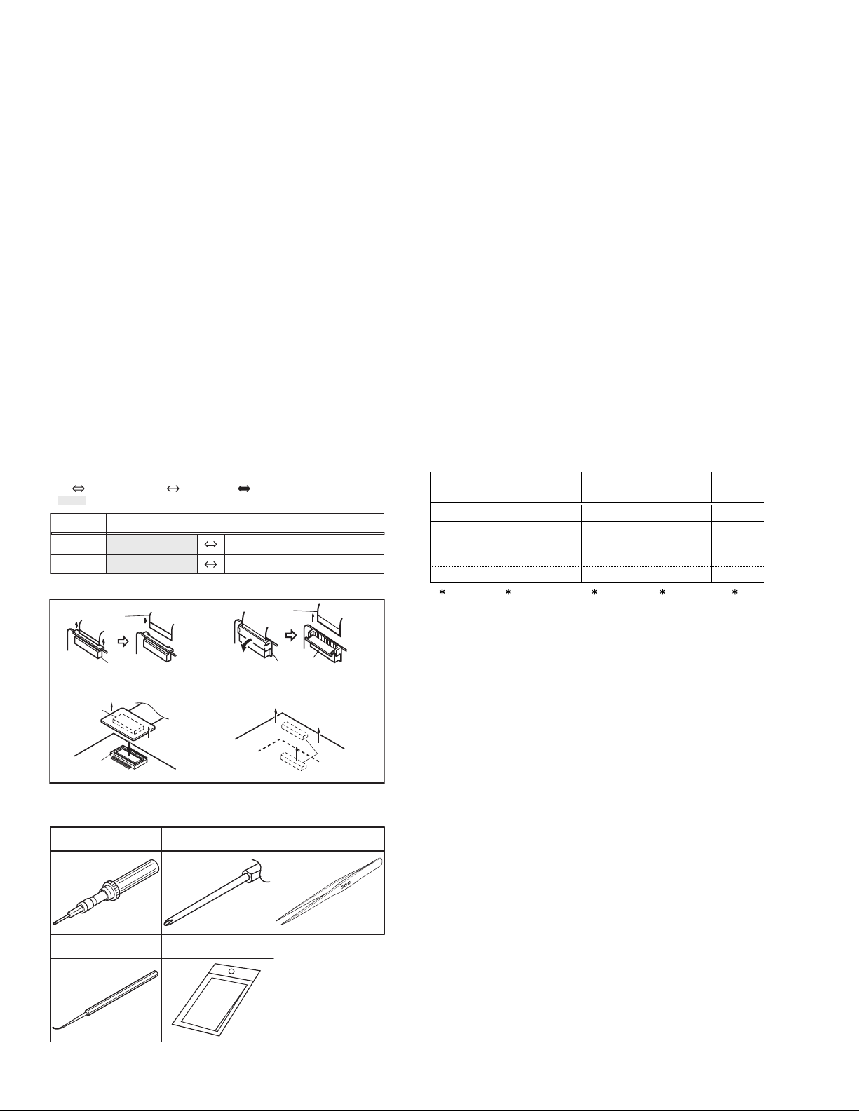
3.1.2 Destination of connectors
Two kinds of double-arrows in connection tables respectively
show kinds of connector/wires.
: Wire: Flat wire : Board to board (B-B)
: The connector of the side to remove
CONN. No. PIN No.CONNECTOR
CN2a
CN2b
MAIN CN101
MAIN CN103
MONI BW CN761
MINI BW CN762
3.1.3 Disconnection of connectors (Wires)
Wire
· Pull both ends of the connector in the arrow
direction, remove the lock and disconnect the flat
wire.
B-B Connector
B-B Connector
· Pull the both ends of the board in the direction of the arrow, and remove the B-B Connector.
FPC Connector
· Extend the locks in the direction of the arrow for
unlocking and then pull out the wire. After
removing the wire, immediately restore the locks
to their original positions because the locks are
apt to come off the connector.
Wire
FPC Connector
Lock
B-B Connector
Fig.3-1-1
3.1.4 Tools required for disassembly and assembly
Torque driver
YTU94088
Bit
YTU94088-003
Tweezers
P-895
·m
40
10
• Torque driver
Be sure to use to fastening the mechanism and exterior parts
because those parts must strictly be controlled for tightening
torque.
• Bit
This bit is slightly longer than those set in conventional torque
drivers.
• Tweezers
To be used for removing and installing parts and wires.
• Chip IC replacement jig
To be used for replacement of IC.
• Cleaning cloth
Recommended cleaning cloth to wipe down the video heads,
mechanism (tape transport system), optical lens surface.
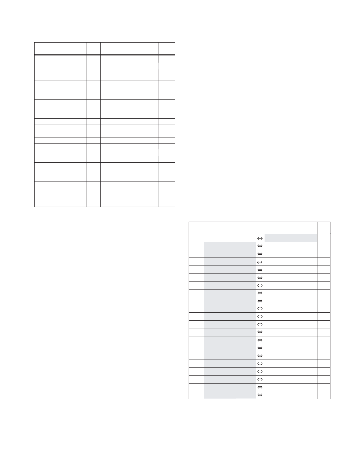
3.2 ASSEMBLY AND DISASSEMBLY OF MAIN PARTS
3.2.1 Assembly and disassembly
When reassembling, perform the step(s) in reverse order.
STEP
No.
[1]
[2]
[8]
PART
TOP COVER ASSY
UPPER ASSY
(Inc. VF ASSY,
SPEAKER/MONITOR)
E.VF UNIT(B/W)
(∗1) Order of steps in Procedure
When reassembling, preform the step(s) in the reverseorder.
These numbers are also used as the identification (location)
No. of parts Figures.
(∗2) Part to be removed or installed.
(∗3) Fig. No. showing Procedure or Part Location.
C = CABINET
(∗4) Identification of part to be removed, unhooked, unlocked,
released, unplugged, unclamped or unsoldered.
S = Screw
L = Lock, Release, Hook
SD = Solder
CN = Connector
[Example]
• 4 (S1a) = Remove 4 S1a screws.
• 3 (L1a) = Disengage 3 L1a hooks.
• 2 (SD1a) = Unsolder 2 SD1a points.
• CN1a = Remove a CN1a connector.
(∗5) Adjustment information for installation.
Fig.
No.
4(S1a), 3(L1a),CN1a
Fig.C1
(S2a),2(S2b),3(S2c)
Fig.C2-1
2(SD1a),
L2,CN2a,b
2(S8),L8,CN8a
Fig.C2-2
POINT
( 4) ( 5)( 2) ( 3)( 1)
NOTE
-
-
NOTE 8
Chip IC replacement jig
PTS40844-2
1-6 (No.YF057)
Cleaning cloth
KSMM-01
Fig.3-1-2
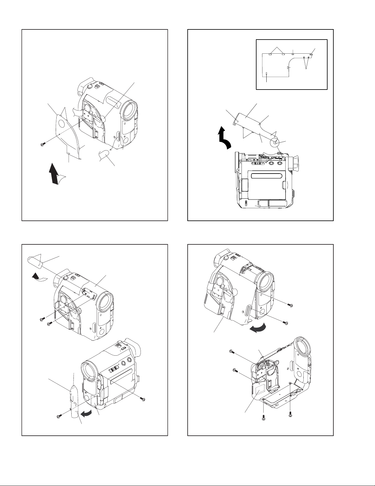
3.2.2 ASSEMBLY/DISASSEMBLY OF CABINET PARTS AND ELECTRICAL PARTS
zDisassembly procedure
STEP
PART NAME
No.
[1]
COVER(PAD)
[2]
COVER(STROBE)
[3]
TOP COVER ASSY
[4]
CASSETTE COVER ASSY
[5]
UPPER CASE ASSY
(INCLUDE MONITOR BOARD)
[6]
FRONT COVER ASSY
[7]
REAR COVER ASSY
[8]
REAR BOARD ASSY
[9]
VF ASSY
[10]
JACK BOARD ASSY
(INCLUDE BASE)
[11]
BKT(TOP)
[12]
ARM ASSY
[13]
SD BOARD ASSY
[14]
FRONT BOARD ASSY
[15]
MAIN BOARD ASSY
[16]
OP BLOCK ASSY
[17]
PRE/MDA BOARD ASSY
[18]
MECHANISM ASSY
Fig.
No.
GRIP BELT,S1,2(L1a),L1b,L1c
C1
COVER(MIC),S2,L2a,L2b
FA1-1
COVER(GRIP),S3a,2(S3b),2(L3a),
FA1-1,2
L3b,L3c,2(L3d),L3e,3(L3f),L3g
CN4,2(S4a),2(S4b),2(S4a)
FA2-1,2
S5a, S5b, GARD BASE,4(S5b),
FA3-1,2
5(S5c),FOOT, S5d,CN5a,CN5b
CN6a,CN6b,2(S6),L6
FA4
2(S7a),S7b
FA5
CN8,2(S8),L8
CN9,S9a,2(S9b)
FA6-1,2
S10,CN10
FA7
3(S11),HEAT ASSY
FA8-1
CN12a,CN12b,2(S12a),4(S12b)
FA8-1,2
3(S13),L13
FA9
S14,2(L14a),L14b
CN15a,CN15b,2(S15),L15a,
FA10
L15b,CN15c,CN15d
CN16,2(S16),L16a,2(L16b)
FA11
2(S17a),SHIELD COVER(PRE),
FA12
L17a,CN17a,CN17b,CN17c,CN17d,
CN17e,CN17f,2(S17b),L17b
3(S18),BKT(MECHA)
FA13
NOTE1a:
Pull out the GRIP BELT from the hook.
NOTE1b:
POINT NOTE
NOTE1a,b
NOTE2a,b
NOTE3
NOTE4a,b
NOTE5a,b
NOTE6
NOTE7
NOTE8
NOTE9
NOTE10
NOTE11
NOTE12a,b
-
-
-
NOTE16
NOTE17
NOTE18
NOTE9:
Be careful in treating and handling the FPC.
NOTE10:
Be careful in treating and handling the FPC.
NOTE11:
Carefully remove the HEAT ASSEMBLY that is placed on the
MAIN BOARD.
When attaching the HEAT ASSEMBLY, pull it into shape and
place it back to it's original position.
NOTE12a:
Detach the ARM ASSEMBLY with the SD BOARD ASSEMBLY attached.
NOTE12b:
Detach the ARM ASSEMBLY with the FRONT BOARD ASSEMBLY attached.
NOTE16:
Be careful with the handling of the OP BLOCK ASSEMBLY.
NOTE17:
When attaching the SHIELD COVER, press the FPC with the
SHIELD COVER.
NOTE18:
When attaching the BRACKET (MECHA), make sure to
place the FPC inside the frame.
zDestination of connectors
CN.NO.
Be careful not to lose the COVER (ADJ).
NOTE2a:
Remove the COVER (MIC), and remove the screw.
NOTE2b:
Be careful not to break the hooks.
NOTE3:
Be careful not to break the hooks.
NOTE4a:
Make sure to pull out the SD card from the holder.
NOTE4b:
Remove the screw (No.9) by opening the MEMORY CARD
COVER.
NOTE5a:
Remove the FOOT, and remove the screw (No.23).
NOTE5b:
Be careful not to get an electric shock by the strobe condenser.
NOTE6:
Be careful not to get an electric shock by the strobe condenser.
NOTE7:
When attaching/detaching the REAR COVER ASSEMBLY,
leave the CASSETTE COVER open, and the VF ASSEMBLY pulled out.
CN4 SPEAKER - SD CN704 2
CN5a MAIN CN105 MONITOR
CN5b MAIN CN112 JUNCTION CN901 18
CN6a MAIN CN111 MIC - 4
CN6b MAIN CN110 STROBE UNIT - 16
CN8 MAIN CN104 REAR CN501 40
CN9 MAIN CN103 VF, ZOOM CN7001,CN1
CN10 MAIN CN108 JACK CN301 16
CN12a SD CN701 MAIN CN102 25
CN12b FRONT CN1101 MAIN CN109 6
CN15a MAIN CN101 CCD - 24
CN15b MAIN CN102 SD CN701 25
CN15c PRE/MDA CN402 MAIN CN106 40
CN15d PRE/MDA CN401 MAIN CN107 73
CN16 PRE/MDA CN4901 OP BLOCK ASSY - 33
CN17a PRE/MDA CN408 HEAD - 8
CN17b PRE/MDA CN406 SENSOR - 16
CN17c PRE/MDA CN405 CAPSTAN MOTOR - 18
CN17d PRE/MDA CN404 DRUM MOTOR - 11
CN17e PRE/MDA CN407
CN17f PRE/MDA CN403 LOADING MOTOR - 6
NOTE8:
When attaching the REAR BOARD ASSEMBLY, leave the
CASSETTE COVER closed, and be careful not to break the
switch.
CONNECTOR
ROTARY ENCODER SW
CN7601,CN7602
39/20,20
31/20,6
- 6
PIN
NO.
(No.YF057)1-7
BOTTOM VIEW
2L3d
L3e
L3g
[1]
1
(S1)
L1a
L1c
L1b
Fig.C1
COVER(ADJ)
NOTE1b
GRIP BELT
NOTE1a
L3b
L3d
L3c
2L3f
L3b
[3]
L3c
L3f
NOTE3
L3g
L3e
Fig.FA1-2
L3a
4
(S3b)
[2]
COVER(GRIP)
5
(S3b)
NOTE2b
2
(S2)
L2b
L2a
Fig.FA1-1
[3]
COVER(MIC)
NOTE2a
3
(S3a)
[4]
8
(S4b)
9
(S4b)
NOTE4b
NOTE4a
CN4
10
(S4a)
Fig.FA2-1
6
(S4a)
7
(S4a)
11
(S4a)
1-8 (No.YF057)
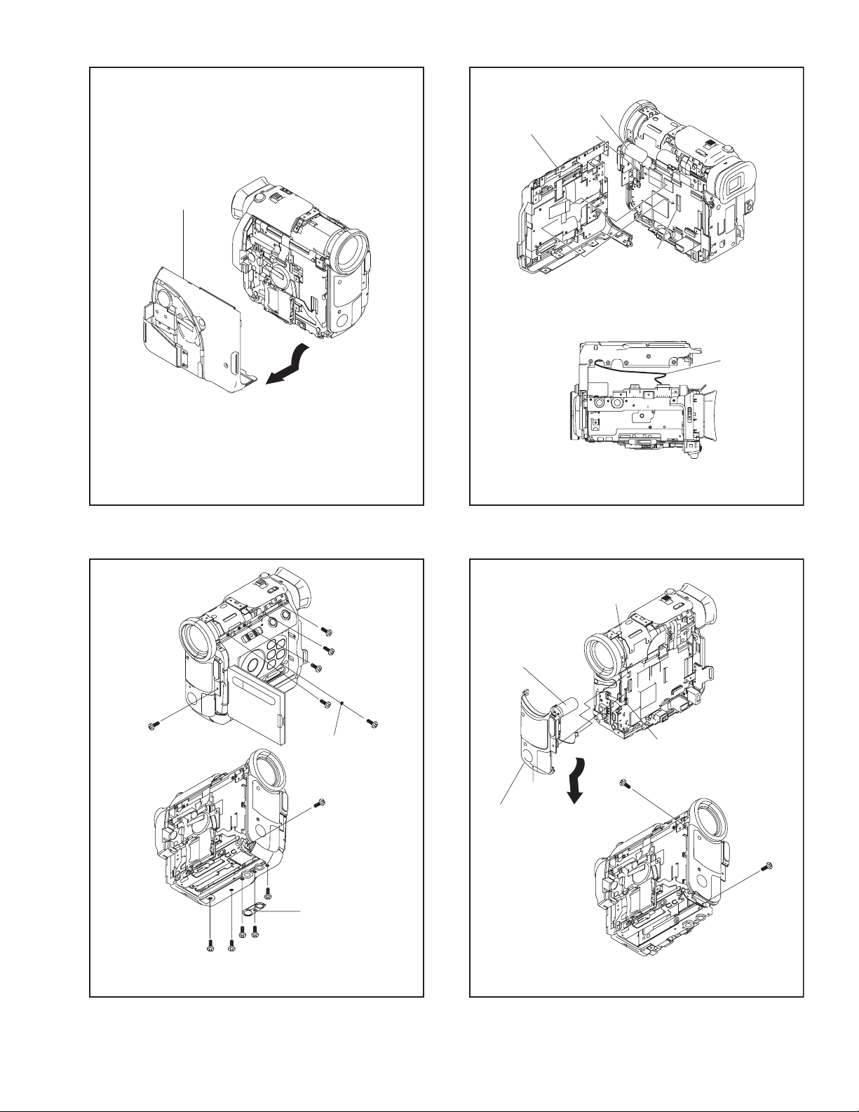
[4]
[5]
NOTE5b
CN5b
CN5a
FPC
(MONI)
18
(S5c)
17
17
(S5b)
(S5b)
16
(S5b)
Fig.FA2-2
22
(S5c)
21
(S5c)
20
(S5c)
19
(S5c)
FOOT
NOTE5a
12
(S5a)
14
(S5b)
GARD BASE
13
(S5b)
㧖
15
(S5b)
㧖0.088Nm (0.9kgfcm)
Fig.FA3-1
23
(S5d)
NOTE6
[6]
L6
Fig.FA3-2
CN6b
CN6a
24
(S6)
25
(S6)
Fig.FA4
(No.YF057)1-9
Loading...