


COMPACT
VHS CAMCORDER
GR-SXM720
INSTRUCTIONS
For Customer Use:
Enter below the Model No. and Serial No. which is located on the bottom of cabinet. Retain this information for future reference.
Model No.
Serial No.
|
ENGLISH |
|
CONTENTS |
|
|
SAFETY PRECAUTIONS |
2 – 5 |
|
QUICK OPERATION GUIDE |
6 |
|
MAJOR FEATURES |
|
7 |
PROVIDED ACCESSORIES |
|
7 |
GETTING STARTED |
8 – 17 |
|
RECORDING |
18 – 34 |
|
Basic Recording .......................... |
|
18 |
Basic Features ........................... |
|
20 |
Advanced Features ...................... |
|
24 |
PLAYBACK |
35 – 39 |
|
Basic Playback ........................... |
|
35 |
Features .................................. |
|
36 |
Using The Cassette Adapter ........... |
|
37 |
Connections ............................... |
|
38 |
USING THE REMOTE |
|
|
CONTROL UNIT |
40 – 44 |
|
Playback Zoom .......................... |
|
41 |
Insert Editing ............................. |
|
42 |
Audio Dubbing ........................... |
|
43 |
Animation And Time-Lapse ............. |
|
44 |
USER MAINTENANCE |
|
45 |
TROUBLESHOOTING |
46 – 47 |
|
INDEX |
48 – 51 |
|
Controls, Connectors And |
|
|
Indicators ............................... |
|
48 |
Indications ................................ |
|
50 |
CAUTIONS |
52 – 53 |
|
TERMS |
|
54 |
SPECIFICATIONS |
|
55 |
ESPAÑOL |
56 – 57 |
|
FOR SERVICING (Only in U.S.A.) |
58 |
|
WARRANTY (Only in U.S.A.) |
59 |
|
LYT0466-001B |
EN |
|
2
 EN
EN


Dear Customer,
Thank you for purchasing the JVC Compact VHS camcorder. Before use, please read the safety information and precautions contained in the following pages to ensure safe use of this product.
Using This Instruction Manual
•All major sections and subsections are listed in the Table Of Contents on the cover. •Notes appear after most subsections. Be sure to read these as well.
•Basic and advanced features/operation are separated for easier reference.
It is recommended that you . . .
.... refer to the Index (Z pgs. 48 – 51) and familiarize yourself with button locations, etc. before use.
.... read thoroughly the Safety Precautions and Safety Instructions that follow. They contain extremely important information regarding the safe use of this product.
You are recommended to carefully read the cautions on pages 52 – 53 before use.
SAFETY PRECAUTIONS
CAUTION
RISK OF ELECTRIC SHOCK
DO NOT OPEN
CAUTION: TO REDUCE THE RISK OF ELECTRIC SHOCK, DO NOT REMOVE COVER (OR BACK).
NO USER-SERVICEABLE PARTS INSIDE.
REFER SERVICING TO QUALIFIED SERVICE PERSONNEL.
The lightning flash with arrowhead symbol, within an equilateral triangle, is intended to alert the user to the presence of uninsulated "dangerous voltage" within the product's enclosure that may be of sufficient magnitude to constitute a risk of electric shock to persons.
The exclamation point within an equilateral triangle is intended to alert the user to the presence of important operating and maintenance (servicing) instructions in the literature accompanying the appliance.
The AA-V16U AC Power Adapter/Charger should be used with:
AC 120 V`, 60 Hz in the USA and Canada, AC 110 – 240 V`, 50/60 Hz in other countries.
CAUTION (applies to the AA-V16U)
TO PREVENT ELECTRIC SHOCK MATCH WIDE BLADE OF PLUG TO WIDE SLOT, FULLY INSERT.
ATTENTION (s’applique à l’AA-V16U)
POUR ÉVITER LES CHOCS ÉLECTRIQUES, INTRODUIRE LA LAME LA PLUS LARGE DE LA FICHE DANS LA BORNE CORRESPONDANTE DE LA PRISE ET POUSSER JUSQU’AU FOND.
This Class B digital apparatus complies with Canadian ICES-003.
Cet appareil numérique de la classe B est conforme à la norme NMB-003 du Canada.
WARNING:
TO PREVENT FIRE OR SHOCK HAZARD, DO NOT EXPOSE THIS UNIT TO RAIN OR MOISTURE.
Warning on lithium battery (for clock operation)
The battery used in this device may present a fire or chemical burn hazard if mistreated. Do not recharge, disassemble, heat above 100°C (212°F) or incinerate.
Replace the battery with Maxell, Panasonic (Matsushita Electric), Sanyo or Sony CR2025; use of another battery may present a risk of fire or explosion.
nDispose of used battery promptly.
nKeep away from children.
nDo not disassemble and do not dispose of in fire.
NOTES:
cThe rating plate (serial number plate) and safety caution are on the bottom and/or the back of the main unit.
cThe rating information and safety caution of the AC Power Adapter/Charger are on its bottom.


 EN3
EN3
This camcorder is designed to be used with NTSC-type color television signals. It cannot be used for playback with a television of a different standard. However, live recording and LCD monitor/viewfinder playback are possible anywhere. Use the BN-V11U/V12U/V20U battery packs and, to recharge them, the provided multi-voltage AC Power Adapter/Charger. (An appropriate conversion adapter may be necessary to accommodate different designs of AC outlets in different countries.)
ATTENTION:
The product that you have purchased is powered by a rechargeable battery. The battery is recyclable. At the end of its useful life, under various state and local laws, it may be illegal to dispose of this battery into the municipal waste stream. Check with your local solid waste officials for details in your area for recycling options or proper disposal.
The EPA certified RBRC® Battery Recycling Seal on the nickel-cadmium (Ni-Cd) battery indicates JVC is voluntarily participating in an industry program to collect and recycle these batteries at the end of their useful life, when taken out of service in the United States. The RBRC® program provides a convenient alternative to placing used Ni-Cd batteries into the trash or the municipal waste stream, which may be illegal in your area. Please call 1-800-8-BATTERY™ for information on Ni-Cd battery recycling and disposal bans/restrictions in your area. JVC’s involvement in this program is part of our commitment to preserving our environment and conserving our natural resources.
When the equipment is installed in a cabinet or on a shelf, make sure that is has sufficient space on all sides to allow for ventilation (10 cm (3-15/16") or more on both sides, on top and at the rear).
Do not block the ventilation holes.
(If the ventilation holes are blocked by a newspaper, or cloth etc. the heat may not be able to get out.)
No naked flame sources, such as lighted candles, should be placed on the apparatus.
When discarding batteries, environmental problems must be considered and the local rules or laws governing the disposal of these batteries must be followed strictly.
The apparatus shall not be exposed to dripping or splashing.
Do not use this equipment in a bathroom or places with water.
Also do not place any containers filled with water or liquids (such as cosmetics or medicines, flower vases, potted plants, cups etc.) on top of this unit.
(If water or liquid is allowed to enter this equipment, fire or electric shock may be caused.)
INFORMATION
This device complies with Part 15 of FCC Rules. Operation is subject to the following two conditions:
(1) This device may not cause harmful interference, and (2) this device must accept any interference received, including interference that may cause undesired operation.
Change or modifications not approved by the party responsible for compliance could void the user’s authority to operate the equipment. This equipment has been tested and found to comply with the limits for a Class B digital device, pursuant to Part 15 of the FCC Rules. These limits are designed to provide reasonable protection against harmful interference in a residential installation. This equipment generates, uses, and can radiate radio frequency energy and, if not installed and used in accordance with the instructions, may cause harmful interference to radio communications. However, there is no guarantee that interference will not occur in a particular installation. If this equipment does cause harmful interference to radio or television reception, which can be determined by turning the equipment off and on, the user is encouraged to try to correct the interference by one or more of the following measures:
Reorient or relocate the receiving antenna.
Increase the separation between the equipment and receiver.
Connect the equipment into an outlet on a circuit different from that to which the receiver is connected. Consult the dealer or an experienced radio/TV technician for help.

4
 EN
EN


IMPORTANT PRODUCT SAFETY INSTRUCTIONS
Electrical energy can perform many useful functions. But improper use can result in potential electrical shock or fire hazards. This product has been engineered and manufactured to assure your personal safety. In order not to defeat the built-in safeguards, observe the following basic rules for its installation, use and servicing.
ATTENTION:
Follow and obey all warnings and instructions marked on your product and its operating instructions. For your safety, please read all the safety and operating instructions before you operate this product and keep this manual for future reference.
5. Ventilation
Slots and openings in the cabinet are provided for ventilation. To ensure reliable operation of the product and to protect it from overheating, these openings must not be blocked or covered.
•Do not block the openings by placing the product on a bed, sofa, rug or other similar surface.
•Do not place the product in a built-in installation such as a bookcase or rack unless proper ventilation is provided or the manufacturer’s instructions have been adhered to.
6. Wall or Ceiling Mounting
The product should be mounted to a wall or ceiling only as recommended by the manufacturer.
ANTENNA INSTALLATION INSTRUCTIONS
1. Outdoor Antenna Grounding
INSTALLATION
1. Grounding or Polarization
(A)Your product may be equipped with a polarized alternating-current line plug (a plug having one blade wider than the other). This plug will fit into the power outlet only one way. This is a safety feature.
If you are unable to insert the plug fully into the outlet, try reversing the plug. If the plug should still fail to fit, contact your electrician to replace your obsolete outlet. Do not defeat the safety purpose of the polarized plug.
(B)Your product may be equipped with a 3-wire grounding-type plug, a plug having a third (grounding) pin. This plug will only fit into a grounding-type power outlet. This is a safety feature.
If you are unable to insert the plug into the outlet, contact your electrician to replace your obsolete outlet. Do not defeat the safety purpose of the grounding-type plug.
2. Power Sources
Operate your product only from the type of power source indicated on the marking label. If you are not sure of the type of power supply to your home, consult your product dealer or local power company. If your product is intended to operate from battery power, or other sources, refer to the operating instructions.
3. Overloading
Do not overload wall outlets, extension cords, or integral convenience receptacles as this can result in a risk of fire or electric shock.
4. Power Cord Protection
Power supply cords should be routed so that they are not likely to be walked on or pinched by items placed upon or against them, paying particular attention to cords at plugs, convenience receptacles, and the point where they exit from the product.
If an outside antenna or cable system is connected to the product, be sure the antenna or cable system is grounded so as to provide some protection against voltage surges and built-up static charges. Article 810 of the National Electrical Code, ANSI/NFPA 70, provides information with regard to proper grounding of the mast and supporting structure, grounding of the lead-in wire to an antenna discharge unit, size of grounding conductors, location of antenna discharge unit, connection to grounding electrodes, and requirements for the grounding electrode.
2. Lightning
For added protection for this product during a lightning storm, or when it is left unattended and unused for long periods of time, unplug it from the wall outlet and disconnect the antenna or cable system. This will prevent damage to the product due to lightning and power-line surges.
3. Power Lines
An outside antenna system should not be located in the vicinity of overhead power lines or other electric light or power circuits, or where it can fall into such power lines or circuits. When installing an outside antenna system, extreme care should be taken to keep from touching such power lines or circuits as contact with them might be fatal.
EXAMPLE OF ANTENNA GROUNDING AS PER NATIONAL ELECTRICAL CODE, ANSI/NFPA 70
|
ANTENNA |
|
LEAD IN WIRE |
GROUND CLAMP |
|
|
ANTENNA |
|
DISCHARGE UNIT |
|
(NEC SECTION |
ELECTRIC SERVICE |
810-20) |
EQUIPMENT |
GROUNDING CONDUCTORS |
|
|
|
(NEC SECTION 810-21) |
|
GROUND CLAMPS |
POWER SERVICE GROUNDING ELECTRODE SYSTEM (NEC ART 250. PART H)
NEC – NATIONAL ELECTRICAL CODE

USE
1. Accessories
To avoid personal injury:
•Do not place this product on an unstable cart, stand, tripod, bracket or table. It may fall, causing serious injury to a child or adult, and serious damage to the product.
•Use only with a cart, stand, tripod, bracket, or table recommended by the manufacturer or sold with the product.
•Use a mounting accessory recommended by the manufacturer and follow the manufacturer’s instructions for any mounting of the product.
•Do not try to roll a cart with small casters across thresholds or deep-pile carpets.
2. Product and Cart |
PORTABLE CART WARNING |
Combination |
(Symbol provided by RETAC) |
|
A product and cart
combination should be moved with care. Quick
stops, excessive force, and uneven surfaces may cause
the product and cart combination to overturn.
3. Water and Moisture
Do not use this product near water—for example, near a bath tub, wash bowl, kitchen sink or laundry tub, in a wet basement, or near a swimming pool and the like.
4. Object and Liquid Entry
Never push objects of any kind into this product through openings as they may touch dangerous voltage points or short-out parts that could result in a fire or electric shock. Never spill liquid of any kind on the product.
5. Attachments
Do not use attachments not recommended by the manufacturer of this product as they may cause hazards.
6. Cleaning
Unplug this product from the wall outlet before cleaning. Do not use liquid cleaners or aerosol cleaners. Use a damp cloth for cleaning.
7. Heat
The product should be situated away from heat sources such as radiators, heat registers, stoves, or other products (including amplifiers) that produce heat.


 EN5
EN5
SERVICING
1. Servicing
If your product is not operating correctly or exhibits a marked change in performance and you are unable to restore normal operation by following the detailed procedure in its operating instructions, do not attempt to service it yourself as opening or removing covers may expose you to dangerous voltage or other hazards. Refer all servicing to qualified service personnel.
2. Damage Requiring Service
Unplug this product from the wall outlet and refer servicing to qualified service personnel under the following conditions:
a.When the power supply cord or plug is damaged.
b.If liquid has been spilled, or objects have fallen into the product.
c.If the product has been exposed to rain or water.
d.If the product does not operate normally by following the operating instructions. Adjust only those controls that are covered by the operating instructions as an improper adjustment of other controls may result in damage and will often require extensive work by a qualified technician to restore the product to its normal operation.
e.If the product has been dropped or damaged in any way.
f.When the product exhibits a distinct change in performance—this indicates a need for service.
3. Replacement Parts
When replacement parts are required, be sure the service technician has used replacement parts specified by the manufacturer or have the same characteristics as the original part. Unauthorized substitutions may result in fire, electric shock or other hazards.
4. Safety Check
Upon completion of any service or repairs to this product, ask the service technician to perform safety checks to determine that the product is in safe operating condition.
6
 EN
EN


 QUICK
QUICK
 OPERATION
 GUIDE
GUIDE


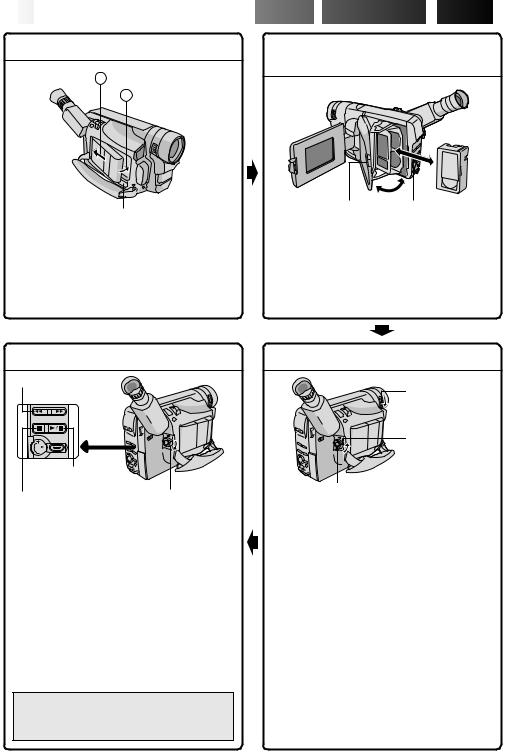
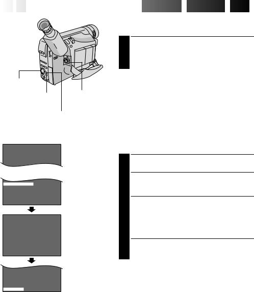
SUPPLY POWER |
INSERTING A VIDEO |
A Hook on. |
CASSETTE |
|
|
B Push in. |
|
PUSH Button |
EJECT Switch |
BATTERY RELEASE
Using the battery pack
Hook its end to the camcorder  and push the battery pack in until it locks in place
  . (Charging procedure, Z pg. 8)
To remove the battery pack
Slide BATTERY RELEASE and pull out the battery pack.
1 Open the LCD monitor fully.
2 Slide EJECT to open the cassette holder.
3 Insert a video cassette.
4 Press PUSH to close the cassette holder. (For more details, Z pg. 13)
PLAYBACK
2Rewind (2) Button
3Play/Pause (4/6) |
|
Button |
|
Stop (5) Button |
1 Set to |
|
“PLAY”. |
1 Set the Power Switch to “PLAY”.
2Press 2.
—The tape will automatically stop at the beginning of the tape.
3Press 4/6.
—Playback starts and the playback picture appears.
•To stop playback, press 5. (For more details, Z pg. 35.)
•The viewfinder switches off automatically to save power when the LCD monitor is opened at an angle of over 60 degrees.
•The LCD monitor turns on/off when it is opened/closed at approx. 60 degrees.
Or simply play back the tape on a VHS VCR
using the Cassette Adapter (VHS Playpak). Z pg. 37
SHOOTING
1
LENS COVER
Open/Close Ring
2
Set to “AUTO” or “PRO.”.
3Recording Start/Stop Button
1 Turn the LENS COVER Open/Close Ring to open the lens cover.
2Set the Power Switch to “AUTO” or “PRO.”.
—The power lamp will light and an image will appear.
3Press the Recording Start/Stop Button.
— Recording starts.
•To stop recording temporarily, momentarily press the Recording Start/Stop Button once again.
(For more details, Z pgs. 18, 19)
•The viewfinder switches off automatically to save power when the LCD monitor is opened at an angle of over 60 degrees.
•The LCD monitor turns on/off when it is opened/closed at approx. 60 degrees.

 MAJOR
MAJOR
 FEATURES


 EN7
EN7
Integrated Auto Light |
TBC (Time Base Corrector) |
||
(Z pg. 22) |
|
(Z pg. 36) |
|
Program AE with Special |
Picture Stabilizer (Z pg. 20) |
||
Effects (Z pg. 25) |
|
|
|
n Electronic Fog Filter |
n ND Effect |
|
|
n Sepia n Twilight n Sports n Nega/Posi |
|
|
|
n 1/2000 sec. High Speed Shutter |
|
|
|
Super VHS-ET (Z pg. 14) |
Digital Hyper Zoom |
||
|
|
||
|
|
(Z pg. 20) |
|
PROVIDED ACCESSORIES |
|
|
|
•AC Power |
•Cassette Adapter |
|
|
Adapter/ |
(VHS Playpak) |
|
|
Charger |
C-P7U |
|
|
AA-V16U |
|
•Shoulder Strap |
|
|
|
|
|
•Remote |
|
|
|
Control Unit |
|
|
|
RM-V715U |
•Battery Pack |
|
|
|
BN-V11U |
|
•Lithium Battery |
|
|
|
CR2025 |
|
|
•DC Cord |
(for clock operation) |
NOTES about Automatic Demonstration
Automatic Demonstration takes place when ”DEMO MODE” is set to ”ON” (factory-preset).
nAvailable when the Power Switch is set to ”AUTO” or ”PRO.”.
nOperating the Power Zoom Lever during the demonstration stops the demonstration temporarily. If the Power Zoom Lever is not moved for more than 1 minute after that, the demonstration will resume.
nTo cancel Automatic Demonstration, set the Power Switch to “PRO.” and press MENU while the demo is in progress. This takes you directly to the demo mode’s Setting Menu (so you will not have to go through the main Menu Screen.) Rotate the Select Wheel to select “OFF” and press it. The Menu Screen appears with the highlight bar on “RETURN”. Press it to close the Menu Screen.
*”DEMO MODE” remains ”ON” even if the camcorder power is turned off.
NOTE:
DEMO MODE
OF F
ON
EX I T
Setting Menu
When a tape whose Erase Protection tab is in the position that allows recording is loaded in the camcorder, demonstration is not available.
Cassettes marked 


 and
and 


 can be used with this camcorder.
8
 EN
EN


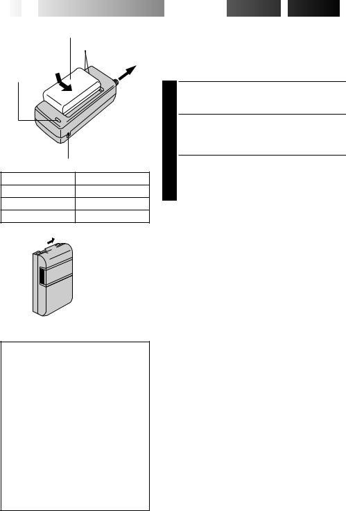
Battery pack BN-V11U,
BN-V12U or BN-V20U
Marks
To AC outlet
CHARGE indicator
|
AC Power |
|
Adapter/Charger |
|
AA-V16U |
DC OUT connector |
|
Battery pack |
Charging time |
BN-V11U |
approx. 1 hr. 10 min. |
BN-V12U (optional) |
approx. 1 hr. 10 min. |
BN-V20U (optional) |
approx. 1 hr. 50 min. |

 Charge marker
ATTENTION:
Charging a battery with some charge remaining reduces that battery’s capacity. Perform the procedure below to fully discharge the battery pack before recharging.
1.Attach the battery pack to the camcorder and make sure a cassette is not inserted, then set the Power Switch to ”AUTO” or ”PRO.”.
2.The camcorder power turns off automatically when discharging is complete.
When you are not using a battery pack for a long period of time, be sure to fully discharge it before storing because leaving a battery with some charge left over also reduces performance.


 GETTING
 STARTED


Power
This camcorder’s 3-way power supply system lets you choose the most appropriate source of power. Do not use provided power supply units with other equipment.
CHARGING THE BATTERY PACK
1 Make sure you unplug the camcorder’s DC cord from the AC Power Adapter/Charger. Plug the AC Adapter/ Charger’s power cord into an AC outlet.
2 Align the marks and slide the battery pack in the direction of the arrow until it locks in place. The CHARGE indicator begins blinking to indicate charging has started.
3 When the CHARGE indicator stops blinking but stays lit, charging is finished. Slide the battery in the opposite direction of the arrow and lift off. Remember to unplug the AC Adapter/Charger’s power cord from the AC outlet.
Charge Marker
A charge marker is provided on the battery pack to help you remember whether it has been charged or not. Two colors are provided (red and black)—you choose which one means charged and which means discharged.
NOTES:
cPerform charging where the temperature is between 10° and 35°C (50°F and 95°F). 20° to 25°C (68°F to 77°F) is the ideal temperature range for charging. If the environment is too cold, charging may be incomplete.
cCharging times noted above are for a fully discharged battery pack.
cCharging time varies according to the ambient temperature and the status of the battery pack.
cTo avoid interference with reception, do not use the AC Power Adapter/Charger near a radio.
cIf you connect the camcorder’s DC cord to the adapter during battery charging, power is supplied to the camcorder and charging stops.
cSince the AC Power Adapter/Charger processes electricity internally, it becomes warm during use. Be sure to use it only in well-ventilated areas.
cWhen charging the battery pack for the first time or after a long storage period, the CHARGE indicator may not light. In this case, remove the battery pack from the AC Power Adapter/Charger, then try charging again.
cIf the battery operation time remains extremely short even after having been fully charged, the battery is worn out and needs to be replaced. Please purchase a new one.
cRemember to set the charge marker after charging a battery pack or after detaching a discharged one from your camcorder.

A Hook on.
B Push in.
BATTERY RELEASE Switch
ATTENTION:
Before detaching the power source, make sure that the camcorder’s power is turned off. Failure to do so can result in a camcorder malfunction.
INFORMATION:
VU-V856KIT is a set composed of the BNV856U battery pack and AA-V80U AC Power Adapter/Charger.
Read the VU-V856KIT’s instruction manuals before using.
It is impossible to charge the BN-V856U battery pack using the provided AC Power Adapter/ Charger. Use the optional AA-V80U AC Power Adapter/Charger.


 EN9
EN9
USING THE BATTERY PACK
Hook its end to the camcorder  and push the battery pack in until it locks in place
  .
.
•If the battery pack is attached in the wrong position, a malfunction may occur.
To Detach The Battery Pack . . .
.... slide BATTERY RELEASE and pull out the battery pack.
Approximate recording time
|
LCD |
LCD |
LCD |
|
|
Battery pack |
monitor off/ |
monitor on/ |
monitor on/ |
|
|
|
Viewfinder on |
Viewfinder off |
Viewfinder on |
|
|
|
|
|
|
|
|
BN-V11U |
1 hr. 30 min. |
1 hr. 20 min. |
1 hr. 15 min. |
|
|
|
(50 min.) |
(45 min.) |
(40 min.) |
|
|
|
|
|
|
|
|
BN-V12U |
1 hr. 30 min. |
1 hr. 20 min. |
1 hr. 15 min. |
|
|
(optional) |
(50 min.) |
(45 min.) |
(40 min.) |
|
|
|
|
|
|
|
|
BN-V20U |
2 hrs. 25 min. |
2 hrs. 10 min. |
2 hrs. |
|
|
(optional) |
(1 hr. 20 min.) |
(1 hr. 15 min.) |
(1 hr. 10 min.) |
|
|
|
|
|
|
|
|
BN-V856U |
9 hrs. 50 min. |
8 hrs. 40 min. |
7 hrs. 50 min. |
|
|
(optional) |
(5 hrs. 40 min.) |
(5 hrs. 10 min.) |
(4 hrs. 50 min.) |
|
|
|
|
|
|
|
|
( ) : when the video light is on.
NOTES:
cRecording time is reduced significantly under the following conditions:
•Zoom or Record-Standby mode is engaged repeatedly.
•The LCD monitor is used repeatedly.
cBefore extended use, it is recommended that you prepare enough battery packs to cover 3 times the planned shooting time.
To DC IN |
To AC outlet |
connector |
|
|
To DC OUT |
|
connector |
Core
filter
AC Power
Adapter/ DC Cord Charger
AA-V16U
To car’s cigarette lighter
Car Battery Cord socket AP-V7U (optional)
Car Battery
Charger/Adapter
BH-V3U (optional)
USING AC POWER
Use the AC Power Adapter/Charger (connect as shown in the illustration).
NOTES:
cThe provided AC Power Adapter/Charger features automatic voltage selection in the AC range from 110 V to 240 V.
cFor other notes, Z pg. 8.
USING A CAR BATTERY
Use the optional Car Battery Cord or Car Battery Charger/ Adapter (connect as shown in the illustration).
NOTES:
cWhen using the car battery, leave the engine idling.
cThe optional Car Battery Charger (BH-V3U) can also be used to charge the battery pack (except BN-V20U/ V856U).
cWhen using the optional Car Battery Charger or Car Battery Cord (AP-V7U), refer to the respective instruction booklet.
10
 EN
EN


 GETTING
 STARTED

 (cont.)

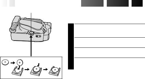
Slot |
Clock (Lithium) Battery Insertion/Removal |
|
|
This battery is necessary for clock operation and to |
|
|
perform date/time settings. |
|
|
Switch off the unit’s power and remove the power |
|
|
1 supply unit (battery pack, AC Power Adapter/Battery |
|
|
Charger, etc.). |
|
|
Pull out the battery holder to remove it from the |
|
|
2 camcorder. |
|
Battery holder |
Insert the battery in the holder, and be sure to have |
|
3 the “+” mark visible. |
||
|
||
|
Slide the holder back into the slot until you hear a |
|
|
4 click. |
NOTES:
cSee “SAFETY PRECAUTIONS” (Z pg. 2) for information on safe handling of lithium batteries.
cTo avoid losing the battery and/or battery holder, place the camcorder with the grip side up as shown in the illustration when inserting/removing the battery.
Select Wheel |
|
|
Power Switch |
|
MENU Button |
|
Display |
4NEXT |
Menu Screen 1 |
|
|
D. ZOOM |
ON |
TELE MACRO |
OF F |
|
ON |
4BACK |
|
OF F |
|
|||
REC T I ME |
|
|||||
I NT . |
T I ME |
OF F |
|
|||
T I T LE |
LANG. |
ENGL I SH |
|
|||
DATE / T I ME |
0 6 |
|
|
|
||
J L I P |
I D NO. |
|
|
|
||
DEMO MODE |
OF F |
|
||||
4RETURN |
|
|
|
|
||
|
|
DATE / T I ME |
|
|||
|
|
|
|
|
|
|
YEAR |
|
2 0 0 0 |
|
|
||
MONTH |
|
|
|
JUN |
|
|
DAY |
|
2 8 |
|
|
||
T I ME |
|
PM 8 : 2 0 |
|
|
||
|
|
|
||||
Menu Screen 2
DATE/TIME Menu
12-hour indication with AM or PM
EX I T |
|
|
4BACK |
|
OF F |
REC T I ME |
||
I NT . |
T I ME |
OF F |
T I T LE |
LANG. |
ENGL I SH |
DATE / T I ME |
0 6 |
|
J L I P |
I D NO. |
|
DEMO MODE |
OF F |
|
4RETURN


 EN11
EN11
Date/Time Settings
1
2 Press MENU. The Menu Screen appears.
3 Rotate the Select Wheel to move the highlight bar to “NEXT” in Menu Screen 1 and press it to display Menu Screen 2. Then, rotate it to move the highlight bar to “DATE/TIME” and press it. The DATE/TIME Menu appears.
•To return to the previous settings, rotate the Select Wheel to move the highlight bar to “EXIT” and press it, then go to step 7.
•To set only the time without changing the date, go to step 5.
4 To set “YEAR”, “MONTH” or “DAY”, rotate the Select Wheel to move the highlight bar to the desired item, and press it. When the setting begins blinking, rotate the Select Wheel until the correct setting appears and then press it. The setting stops blinking.
Repeat for other date settings.
5 Rotate the Select Wheel to move the highlight bar to “TIME” and then press it. When the hour setting begins blinking, rotate the Select Wheel until the correct setting appears and then press it. When the hour setting stops blinking and the minute setting begins blinking, rotate the Select Wheel until the correct setting appears and then press it. The minute setting stops blinking.
6 When none of these settings (“YEAR”, “MONTH”, “DAY”, “TIME”) blinks, rotate the Select Wheel to move the highlight bar to “EXIT”, and press it. The Menu Screen reappears with the highlight bar on “RETURN”.
7 Press the Select Wheel to close the Menu Screen.
NOTE:
To display the date and time in the camcorder’s display and on a connected TV, see “Date/Time Insert”
(Z pg. 29).
12
 EN
EN


 GETTING
 STARTED

 (cont.)

Recording Mode Setting
Set depending on your preference.
1 Set the Power Switch to “AUTO” or “PRO.”. Press SP/ EP for more than 1 second. “SP” (Standard Play) provides higher picture and sound quality and is better for dubbing, while “EP” (Extended Play) is more economical, providing three times the recording time.
Select Wheel |
|
NOTE: |
|
If the recording mode is switched during recording, the |
|
|
|
|
|
Power Switch |
playback picture will be blurred at the switching point. |
SP/EP Recording |
|
|
|
|
|
Mode Button |
|
|
|
|
|
|
|
MENU Button |
||
|
|
|
Viewfinder |
|
|||
|
|
SP |
|
T 3 0 |
|
Tape length indicator |
|
|
|
|
|
||||
|
|
|
|
|
|
||
|
|
|
|
|
|
|
Recording mode |
|
|
|
|
|
|
|
|
|
|
|
|
|
|
|
indicator |
|
|
|
Display |
|
|||
TELE MACRO |
OF F |
|
|||||
TAPE |
|
LENGTH |
|
|
|
Menu Screen |
|
T 3 0 |
|||||||
|
|||||||
4RETURN |
|
|
|
|
|||
|
|
|
TAPE LENGTH |
TAPE LENGTH |
|||
T 2 0 |
|
|
|
|
|
Setting Menu |
|
T 3 0 |
|
|
|
|
|
|
|
T 3 5 |
|
|
|
|
|
|
|
T 4 0 |
|
|
|
|
|
|
|
EX I T |
|
|
|
|
|
|
|
TELE MACRO |
OF F |
|
|||||
TAPE |
|
LENGTH |
T 4 0 |
|
|||
4RETURN
Tape Length Setting
Set the tape length according to the length of the tape used.
1 Set the Power Switch to “PRO.”, then press MENU.
2 Rotate the Select Wheel to move the highlight bar to “TAPE LENGTH”, then press it. The TAPE LENGTH Setting Menu appears.
3 Rotate the Select Wheel to move the highlight bar to the correct tape length setting. T20=20 minutes of recording time, T30=30 minutes, T35=35 minutes, and T40=40 minutes (in SP).
•To return to the previous setting, rotate the Select Wheel to move the highlight bar to “EXIT”.
4 Press the Select Wheel. The Menu Screen reappears with the highlight bar on “RETURN”. Press the Select Wheel again to close the Menu Screen.
NOTE:
The tape remaining time (Z pg. 18) displayed in the viewfinder is correct only if the correct tape length has been selected.
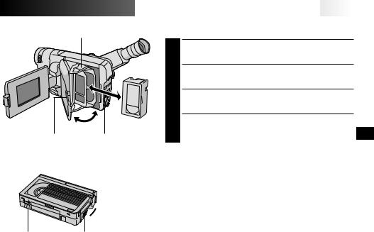
Cassette holder
PUSH Button |
EJECT Switch |
Turn to take
 up slack.
Erase Protection tab |
Gear |


 EN13
EN13
Loading/Unloading A Cassette
1 Open the LCD monitor fully.
2 Slide EJECT until the cassette holder opens. Do not use force to open.
3
4
NOTES:
cClosing the LCD monitor while the cassette holder is still open may cause damage to the LCD monitor.
cThe cassette holder can’t be opened unless a power supply is attached.
cMake sure that the tape is not slack when loading the cassette. If there is any slack, turn the gear on the cassette in the direction of the arrow to take up the slack.
cMake sure the Erase Protection tab is in the position that allows recording. If not, slide the tab. Some cassettes have removable tabs. If the tab has been removed, cover the hole with adhesive tape.
cThe cassette holder cannot be opened while the camcorder is in the record mode.
14
 EN
EN


 GETTING
 STARTED

 (cont.)

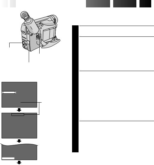
Recording Format Setting
Select Wheel
Power Switch
MENU Button
Display: when a VHS cassette is loaded.
4NEXT |
ON |
|
D. ZOOM |
||
TELE MACRO |
OF F |
|
S – VHS ET |
|
OF F |
TAPE LENGTH |
T 3 0 |
|
4RETURN |
|
|
|
||
Menu Screen
When an S-VHS cassette is loaded: S-VHS
S – VHS ET
|
|
|
Setting Menu |
ON |
|
|
|
OF F |
|
|
|
EX I T |
|
|
|
TELE MACRO |
OF F |
|
|
TAPE LENGTH |
T 3 0 |
Menu Screen |
|
4RETURN |
|
|
|
Set the recording format according to the format of the tape used or type of recording you wish to perform.
1 Set the Power Switch to “PRO.”. Press MENU.
2 If a VHS cassette is loaded . . .
.... rotate the Select Wheel to move the highlight bar to “S-VHS ET”, then press it. The S-VHS ET Setting Menu appears.
If an S-VHS cassette is loaded . . .
.... rotate the Select Wheel to move the highlight bar to “S-VHS”, then press it. The S-VHS Setting Menu appears.
3 Rotate the Select Wheel to set to either of the parameters, then press it. The highlight bar moves to “EXIT”.
In the S-VHS ET Setting Menu,
ON : Records with S-VHS picture quality on a VHS cassette (factory-preset). This is called Super VHS ET (Expansion Technology).
OFF : Records in VHS.
In the S-VHS Setting Menu,
ON : Records in S-VHS on an S-VHS cassette (factory-preset).
OFF : Records in VHS on an S-VHS cassette.
4 Press the Select Wheel. The Menu Screen reappears with the highlight bar on “RETURN”. Press the Select Wheel again to close the Menu Screen.
•When the S-VHS ET mode is engaged, “S-ET” is displayed.
•During S-VHS record mode, “S“ is displayed. •When S-VHS ET or S-VHS recording starts, “S-VHS
REC.” is displayed for approx. 3 seconds.
NOTE:
If a cassette is not loaded, “S-VHS” will be displayed in the Menu Screen.
Normal Screen


 EN15
EN15
NOTES about S-VHS and S-VHS ET
nJVC EHG (Extra High Grade) tapes are recommended for superior results.
Use S-VHS tape for storing recordings for an extended period or for recording important scenes, as it enables higher-quality recording and playback.
nWith some tapes, better picture quality may not be obtained even with S-VHS ET recording. It is recommended that you do test record beforehand to make sure whether better results can be obtained.
nIf the S-VHS ET mode or recording format is switched during recording, the playback picture will be blurred at the switching point.
nIt is recommended that tapes recorded in the SP mode on this camcorder be played back on this camcorder.
nNoise may appear on-screen when tapes recorded in the EP mode are played back.
nTapes recorded in S-VHS or S-VHS ET mode can be played back not only on this camcorder but also on a Super VHS VCR or a VCR equipped with the SQPB (S-VHS QUASI PLAYBACK) function.
—When tapes recorded in S-VHS or S-VHS ET mode are played back on a VCR equipped with the SQPB (S-VHS QUASI PLAYBACK) function, S-VHS picture quality is not available.
—Tapes recorded in S-VHS ET mode cannot be played back on some VCRs, including some JVC VCRs (eg: HR-S6600U, HR-SC1000U, etc.).
nTapes recorded in S-VHS or S-VHS ET mode cannot be played back correctly on a normal VHS VCR.
nYou can play back S-VHS ET recordings not only on this VCR but also on another VHS VCR equipped with S-VHS ET.
—It is recommended to specifically label S-VHS ET recordings so you can easily distinguish them from regular VHS recordings.
nS-VHS ET does not work with S-VHS tapes.
nTo avoid on-screen noise, do not perform Still Playback or Shuttle Search repeatedly.
nIf the picture contains a lot of jitter or noise, use a cleaning cassette.
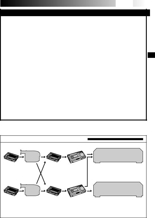
Compatibility Between S-VHS And VHS
Recording |
|
Playback |
|
Blank tape |
Camcorder |
Recorded tape |
Cassette adapter |
S-VHS-C |
|
S-VHS |
cassette |
|
recordings |
VHS-C |
|
VHS |
cassette |
|
recordings |
Blank tape |
Camcorder |
Recorded tape Cassette adapter |
S-VHS VCR VHS VCR with SQPB
function
•The recorded format (S-VHS or VHS) is automatically detected when playback begins.
Regular VHS VCR
•S-VHS recorded tapes cannot be viewed on regular VHS VCRs, other than those equipped with the SQPB (S-VHS QUASI PLAYBACK) function.
16
 EN
EN


 GETTING
 STARTED

 (cont.)

Power Zoom Lever |
Grip Adjustment |
|
1 Separate the Velcro strip. |
|
Pass your right hand through the loop and grasp the |
|
2 grip. |
|
Adjust so that your thumb and fingers can easily |
|
3 operate the Recording Start/Stop Button and Power |
|
Zoom Lever. Refasten the Velcro strip. |
Recording Start/Stop Button
 3
3

 2
2
180°
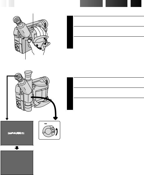
Viewfinder Adjustment
1
2 Adjust the viewfinder manually for best viewability.
3 Turn the Diopter Adjustment Control until the indications in the viewfinder are clearly focused.
1
Set to “CAMERA” (“AUTO” or “PRO.”).
 PAUSE
PAUSE 


 EN17
EN17
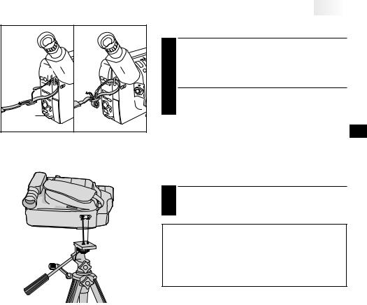
1 |
Shoulder Strap Attachment
1 Following the illustration, thread the strap through the eyelet 1, then fold it back and thread it through the buckle 2. Repeat the procedure to attach the other end of the strap to the other eyelet 3, making sure the strap is not twisted.
2 Adjust as shown in the illustration 4.
Tripod Mounting
1 Align the screw and camera direction stud on the tripod with the camera’s mounting socket and stud hole. Then tighten the screw.
CAUTION:
When using a tripod, be sure to open and extend its legs fully to stabilize the camcorder. To prevent damage to the unit caused by falling over, do not use a small-sized tripod.
18
 EN
EN


 RECORDING
 Basic
Basic
 Recording

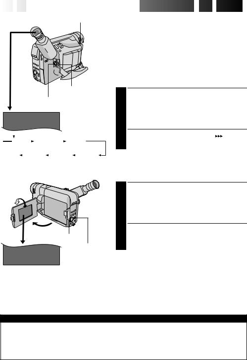
LENS COVER Open/Close Ring
|
|
Power Switch |
|
|
Recording Start/Stop Button |
2 5M |
I N |
Tape remaining time |
|
|
indicator |
|
|
(Approximate) |
|
|
|
MIN |
|
120MIN |
|
|
119MIN |
|
||||
|
|
|
|
|||||||
(Now calculating) |
|
|
|
|
|
|
||||
0MIN |
|
|
1MIN |
|
|
2MIN |
|
|
3MIN |
|
|
|
|
|
|
||||||
(Blinking) |
(Blinking) |
(Blinking) |
|
|||||||
° 90°
180
Select Wheel (BRIGHT)
DISPLAY Button
BR I GHT – – – – – –6– – – – – +
To Adjust The Brightness Of The LCD Monitor
.... rotate the Select Wheel (BRIGHT) until the bright level indicator on the display moves and the appropriate brightness is reached.
NOTE:
You should already have performed the procedures listed below. If not, do so before continuing.
cPower (Z pg. 8)
cRecording Mode Setting (Z pg. 12)
cLoad A Cassette (Z pg. 13)
cGrip Adjustment (Z pg. 16)
cViewfinder Adjustment (Z pg. 16)
Shooting While Watching The
Viewfinder
1 Make sure the LCD monitor is closed and locked. Turn the LENS COVER Open/Close Ring to open the lens cover. Set the Power Switch to “CAMERA” (“AUTO” or “PRO.”). The power lamp lights and the camcorder enters the Record-Standby mode. “PAUSE” is displayed in the viewfinder.
2 Press the Recording Start/Stop Button. “ ” appears in the viewfinder while recording is in progress.
Shooting While Watching The
LCD Monitor
1 Make sure the LCD monitor is fully open. Turn the LENS COVER Open/Close Ring to open the lens cover. Set the Power Switch to “CAMERA” (“AUTO” or “PRO.”). The power lamp lights and the camcorder enters the Record-Standby mode. “PAUSE” is displayed in the LCD monitor.
2 Tilt the LCD monitor upward/downward for best viewability and press the Recording Start/Stop Button. “
 ” appears in the LCD monitor while recording is in progress.
NOTE:
When you use the LCD monitor outdoors in direct sunlight, the LCD monitor may be difficult to see. If this happens, use the viewfinder instead.
To Stop Recording . . .
.... press the Recording Start/Stop Button. The camcorder re-enters the Record-Standby mode.
Power Switch Position
AUTO : Suitable for standard recording using NO special effects or manual adjustments.
PRO. |
: Allows you to set recording functions using the menus for more creative capabilities. |
OFF |
: Switches off the camcorder. |
PLAY |
: Allows you to play back your recordings. |
 Loading...