


 Loading...
DIGITAL VIDEO CAMERA
GR-DVP3 GR-DVP1
Please visit our Homepage on the World Wide Web and answer our Consumer Survey
(in English only):
http://www.jvc-victor.co.jp/english/index-e.html
INSTRUCTIONS
|
ENGLISH |
|
|
CONTENTS |
|
AUTOMATIC |
8 |
DEMONSTRATION |
|
|
|
GETTING STARTED |
9 – 18 |
|
|
VIDEO RECORDING & |
19 – 26 |
PLAYBACK |
|
VIDEO RECORDING ............. |
20 – 22 |
VIDEO PLAYBACK ............... |
23 – 26 |
|
|
DIGITAL STILL CAMERA (D.S.C.) |
|
RECORDING & |
27 – 38 |
PLAYBACK |
|
D.S.C. RECORDING .............. |
28 – 29 |
D.S.C. PLAYBACK ................ |
30 – 38 |
|
|
ADVANCED |
39 – 75 |
FEATURES |
|
USING MENUS FOR |
|
DETAILED ADJUSTMENT ...... |
40 – 46 |
FOR RECORDING ................ |
47 – 57 |
DUBBING ......................... |
58 – 61 |
USING THE REMOTE |
|
CONTROL UNIT ................ |
62 – 73 |
SYSTEM CONNECTIONS ........ |
74 – 75 |
|
|
REFERENCES |
76 – 99 |
DETAILS ................................... |
77 |
TROUBLESHOOTING ............ |
78 – 83 |
USER MAINTENANCE ................... |
84 |
INDEX ............................. |
85 – 92 |
CAUTIONS ........................ |
93 – 95 |
TERMS ............................ |
96 – 97 |
SPECIFICATIONS ................. |
98 – 99 |
|
|
LYT0796-001A EN
2EN
Dear Customer,
Thank you for purchasing this digital video camera. Before use, please read the safety information and precautions contained in the following pages to ensure safe use of this product.
Using This Instruction Manual
•All major sections and subsections are listed in the Table Of Contents on the cover page.
•Notes appear after most subsections. Be sure to read these as well.
•Basic and advanced features/operation are separated for easier reference.
It is recommended that you . . .
..... refer to the Index ( pgs. 85 – 92) and familiarise yourself with button locations, etc. before use.
..... read thoroughly the Safety Precautions and Safety Instructions that follow. They contain extremely important information regarding the safe use of this product.
You are recommended to carefully read the cautions on pages 93 through 95 before use.
SAFETY PRECAUTIONS
IMPORTANT (for owners in the U.K.)
Connection to the mains supply in the United Kingdom.
DO NOT cut off the mains plug from this equipment.
If the plug fitted is not suitable for the power points in your home or the cable is too short to reach a power point, then obtain an appropriate safety approved extension lead or consult your dealer.
BE SURE to replace the fuse only with an identical approved type, as originally fitted, and to replace the fuse cover.
If nonetheless the mains plug is cut off be sure to remove the fuse and dispose of the plug immediately, to avoid possible shock hazard by inadvertent connection to the mains supply.
If this product is not supplied fitted with a mains plug then follow the instructions given below: DO NOT make any connection to the Larger Terminal coded E or Green.
The wires in the mains lead are coloured in accordance with the following code:
Blue to N (Neutral) or Black
Brown to L (Live) or Red
If these colours do not correspond with the terminal identifications of your plug, connect as follows:
Blue wire to terminal coded N (Neutral) or coloured black.
Brown wire to terminal coded L (Live) or coloured Red.
If in doubt — consult a competent electrician.
WARNING:
TO PREVENT FIRE OR SHOCK HAZARD, DO NOT EXPOSE THIS UNIT TO RAIN OR MOISTURE.
CAUTIONS:
To prevent shock, do not open the cabinet. No user serviceable parts inside. Refer servicing to qualified personnel.
When you are not using the AC Power Adapter/Charger for a long period of time, it is recommended that you disconnect the power cord from AC outlet.
NOTES:
●The rating plate (serial number plate) and safety caution are on the bottom and/or the back of the main unit.
●The rating plate (serial number plate) of the AC Power Adapter /Charger is on its bottom.
Caution: (applies to Docking Station)
To reduce the risk of fire, do not remove cover. No user-serviceable parts inside. Refer servicing to qualified service person.

EN3
CAUTIONS:
●This camcorder is designed to be used with PAL-type colour television signals. It cannot be used for playback with a television of a different standard. However, live recording and LCD monitor/viewfinder playback are possible anywhere.
●Use the JVC BN-V107U/V114U battery packs and, to recharge them or to supply power to the camcorder from an AC outlet, use the provided multi-voltage AC Power Adapter /Charger. (An appropriate conversion adapter may be necessary to accommodate different designs of AC outlets in different countries.)
When the equipment is installed in a cabinet or on a shelf, make sure that it has sufficient space on all sides to allow for ventilation (10 cm or more on both sides, on top and at the rear).
Do not block the ventilation holes.
(If the ventilation holes are blocked by a newspaper, or cloth etc. the heat may not be able to get out.)
No naked flame sources, such as lighted candles, should be placed on the apparatus.
When discarding batteries, environmental problems must be considered and the local rules or laws governing the disposal of these batteries must be followed strictly.
The apparatus shall not be exposed to dripping or splashing.
Do not use this equipment in a bathroom or places with water.
Also do not place any containers filled with water or liquids (such as cosmetics or medicines, flower vases, potted plants, cups etc.) on top of this unit.
(If water or liquid is allowed to enter this equipment, fire or electric shock may be caused.)
SOME DO’S AND DON’TS ON THE SAFE USE OF EQUIPMENT
This equipment has been designed and manufactured to meet international safety standards but, like any electrical equipment, care must be taken if you are to obtain the best results and safety is to be assured.
DO read the operating instructions before you attempt to use the equipment.
DO ensure that all electrical connections (including the mains plug, extension leads and interconnections between pieces of equipment) are properly made and in accordance with the manufacturer’s instructions. Switch off and withdraw the mains plug when making or changing connections.
DO consult your dealer if you are ever in doubt about the installation, operation or safety of your equipment.
DO be careful with glass panels or doors on equipment.
DON’T continue to operate the equipment if you are in any doubt about it working normally, or if it is damaged in any way — switch off, withdraw the mains plug and consult your dealer.
DON’T remove any fixed cover as this may expose dangerous voltages.
DON’T leave equipment switched on when it is unattended unless it is specifically stated that it is designed for unattended operation or has a standby mode. Switch off using the switch on the equipment and make sure that your family knows how to do this. Special arrangements may need to be made for infirm or handicapped people.
DON’T use equipment such as personal stereos or radios so that you are distracted from the requirements of road safety. It is illegal to watch television whilst driving.
DON’T listen to headphones at high volume, as such use can permanently damage your hearing.
DON’T obstruct the ventilation of the equipment, for example with curtains or soft furnishings. Overheating will cause damage and shorten the life of the equipment.
DON’T use makeshift stands and NEVER fix legs with wood screws — to ensure complete safety always fit the manufacturer’s approved stand or legs with the fixings provided according to the instructions.
DON’T allow electrical equipment to be exposed to rain or moisture.
ABOVE ALL
—NEVER let anyone especially children push anything into holes, slots or any other opening in the case — this could result in a fatal electrical shock;
—NEVER guess or take chances with electrical equipment of any kind — it is better to be safe than sorry!

4EN
SAFETY PRECAUTIONS
Do not point the lens or the viewfinder directly into the sun. This can cause eye injuries, as well as lead to the malfunctioning of internal circuitry. There is also a risk of fire or electric shock.
CAUTION!
The following notes concern possible physical damage to the camcorder and to the user.
When carrying, be sure to always securely attach and use the provided strap. Carrying or holding the camcorder by the viewfinder and/or the LCD monitor can result in dropping the unit, or in a malfunction.
Take care not to get your finger caught in the cassette holder cover. Do not let children operate the camcorder, as they are particularly susceptible to this type of injury.
Do not use a tripod on unsteady or unlevel surfaces. It could tip over, causing serious damage to the camcorder.
CAUTION!
Attaching the camcorder to the Docking Station with cables (S-Video, Editing, etc.) connected, then leaving it on top of the TV is not recommended, as tripping on the cables will cause the camcorder to fall, resulting in damage.
Attach only the optional JVC VL-V3U Video Light, VL-F3U Video Flash or MZ-V3U Stereo Zoom Microphone to the camcorder’s Info-Shoe.
This camcorder is designed exclusively for the digital video cassette, SD Memory Card and MultiMediaCard. Only cassettes marked “

 ” and memory cards marked “

 ” or
” or
“


 ” can be used with this unit.
Before recording an important scene . . .
.... make sure you only use cassettes with the Mini DV mark |
|
. |
.... make sure you only use memory cards with the mark |
or |
. |
.... remember that this camcorder is not compatible with other digital video formats.
.... remember that this camcorder is intended for private consumer use only. Any commercial use without proper permission is prohibited. (Even if you record an event such as a show, performance or exhibition for personal enjoyment, it is strongly recommended that you obtain permission beforehand.)
EN5
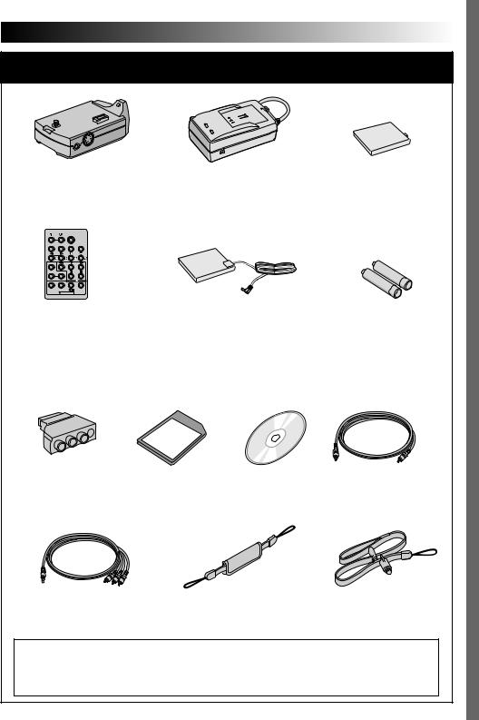
PROVIDED ACCESSORIES
• Docking Station |
• AC Power Adapter/Charger |
• Battery Pack |
CU-V507U |
AA-V100EG or AA-V100EK |
BN-V107U |
• Remote Control Unit |
• DC Cord |
• AAA (R03) Battery x 2 |
RM-V717U |
|
(for remote control unit) |
• Cable Adapter |
• Memory Card 8 MB |
• CD-ROM |
• Editing Cable |
|
(Already inserted in the |
|
|
|
camcorder) |
|
|
• Audio/Video Cable |
• Grip Belt |
•Strap |
(ø3.5 mini-plug to RCA plug) |
( pg. 6 for attachment) |
( pg. 7 for attachment) |
NOTE:
In order to maintain optimum performance of the camcorder, provided cables may be equipped with one or more core filter. If a cable has only one core filter, the end that is closest to the filter should be connected to the camcorder.
6EN
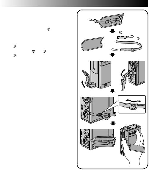
How To Attach The Grip Belt
1 Remove the pad and separate the two straps.
2 Thread one end of the strap |
through the |
1 |
|
eyelet, then pass the other end through the |
|
||
loop. |
|
|
|
3 Repeat the same procedure to attach the |
|
||
strap |
to the other eyelet. |
|
|
4 Connect the strap and |
and thread the |
|
|
strap |
through the buckle, then adjust the |
|
|
grip ( pg. 12). |
|
|
|
5 Attach the pad. |
2 |
3 |
|
|
|
||
4
5
EN7
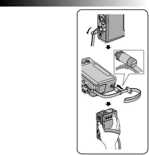
How To Attach The Strap
1 Thread one end of the strap through the |
|
eyelet, then pass the other end through the |
1 |
loop.
2 Attach the screw to the tripod mounting socket. To tighten the screw firmly, use a coin, etc.
3 Adjust the length with the adjuster.
NOTES:
●You can use the strap as a shoulder strap by adjusting the length with the adjuster.
●Because a loose screw may cause damage to the camcorder, make sure to tighten the screw firmly to the tripod mounting socket when carrying the camcorder.
●Use the strap only with this camcorder.
●Do not grip the camcorder too firmly when the screw is attached. Doing so may cause damage to the tripod mounting socket.
2 3
8EN
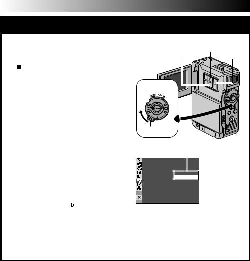
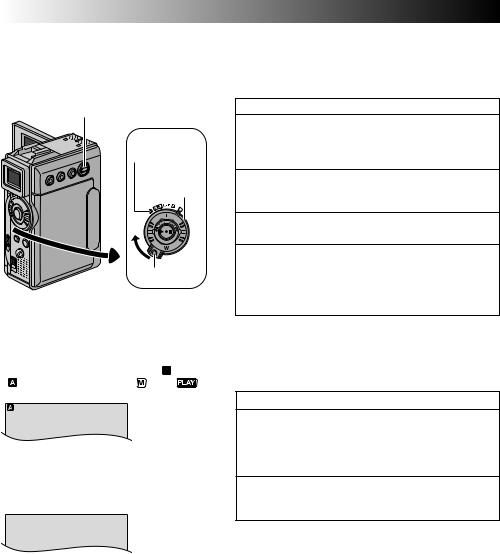
AUTOMATIC DEMONSTRATION
Automatic Demonstration takes place when “DEMO MODE” is set to “ON” (factory-preset).
Available when the Power Switch is set to “ ” or “
 ” and no cassette is in the camcorder.
Performing any operation during the demonstration stops the demonstration temporarily. If no operation is performed for more than 1 minute after that, the demonstration will resume.
“DEMO MODE” remains “ON” even if the camcorder power is turned off.
To cancel Automatic Demonstration:
1.Set the Power Switch to “ ” while pressing down the Lock Button located on the switch and press MENU. The Menu Screen appears.
2.Press + or – to select “ SYSTEM” and press SET/SELECT. The SYSTEM Menu appears.
3.Press + or – to select “DEMO MODE” and press SET/SELECT. The Sub Menu appears.
4.Press + or – to select “OFF” and press SET/ SELECT.
5.Press + or – to select “ RETURN”, and press SET/SELECT twice. The normal screen appears.
NOTE:
If you do not slide the lens cover down, you cannot see the actual changes of the Automatic Demonstration activated on the LCD monitor or viewfinder.
MENU Button
SET/SELECT Button |
+, – Button |
Power Switch
Lock Button
Sub Menu
DEMO MODE – OFF
ON

GETTING STARTED |
EN9 |
GETTING STARTED |
|
CONTENTS |
|
Power ................................................................ |
10 – 11 |
Grip Adjustment ............................................................. |
12 |
Viewfinder Adjustment .................................................... |
12 |
Tripod Mounting ............................................................. |
12 |
Date/Time Settings ......................................................... |
13 |
Loading/Unloading A Cassette ........................................... |
14 |
Recording Mode Setting ................................................... |
15 |
Loading A Memory Card ................................................... |
16 |
Picture Quality Mode Setting ............................................. |
17 |
Image Size Mode Setting .................................................. |
17 |
Operation Mode ............................................................. |
18 |
10 EN
|
Protruding part |
|
Battery pack |
CHARGE |
To |
indicator |
|
POWER |
AC outlet |
indicator |
|
|
AC Power |
|
Adapter/Charger |
DC OUT connector |
|
Battery pack |
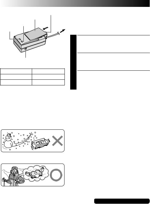
Charging time |
BN-V107U |
approx. 1 hr. 30 min. |
BN-V114U (optional) |
approx. 2 hr. |
NOTES:
GETTING STARTED (cont.)
Power
This camcorder’s 2-way power supply system lets you choose the most appropriate source of power. Do not use provided power supply units with other equipment.
CHARGING THE BATTERY PACK
1 Make sure you unplug the camcorder’s DC cord from the AC Power Adapter/Charger. Plug the AC Adapter/ Charger’s power cord into an AC outlet. The POWER indicator lights.
2 Attach the battery pack with the 
 mark aligned with the corresponding marks on the AC Power Adapter/Charger. The CHARGE Indicator begins blinking to indicate charging has started.
3 When the CHARGE indicator stops blinking but stays lit, charging is finished. Remove the battery by pushing up the protruding part. Remember to unplug the AC Adapter/Charger’s power cord from the AC outlet.
●If the protective cap is attached to the battery pack, remove it first.
●If you connect the camcorder’s DC cord to the AC Power Adapter/Charger during battery charging, power is supplied to the camcorder and charging stops.
●When charging the battery pack for the first time or after a long storage period, the CHARGE indicator may not light. In this case, remove the battery pack from the AC Power Adapter/Charger, then try charging again.
●If the battery operation time remains extremely short even after having been fully charged, the battery is worn out and needs to be replaced. Please purchase a new one.
Lithium-ion is vulnerable in colder temperatures.
About Batteries
DANGER! Do not attempt to take the batteries apart, or expose them to flame or excessive heat, as it may cause a fire or explosion.
WARNING! Do not allow the battery or its terminals to come in contact with metals, as this can result in a short circuit and possibly start a fire.
The Benefits Of Lithium-Ion Batteries
Lithium-ion battery packs are small but have a large power capacity. However, when one is exposed to cold temperatures (below 10°C), its usage time becomes shorter and it may cease to function. If this happens, place the battery pack in your pocket or other warm, protected place for a short time, then re-attach it to the camcorder. As long as the battery pack itself is not cold, it should not affect performance.
(If you’re using a heating pad, make sure the battery pack does not come in direct contact with it.)
For other notes, pg. 77
1


Notches
2
BATT. RELEASE Switch
ATTENTION:
Before detaching the power source, make sure that the camcorder’s power is turned off. Failure to do so can result in a camcorder malfunction.
INFORMATION:
The extended-use battery pack kit is a set composed of a battery pack and AC Power Adapter/Charger:
VU-V840 KIT: BN-V840U battery pack & AAV15EG or AA-V15EK AC Power Adapter/Charger VU-V856 KIT: BN-V856U battery pack & AAV80EG or AA-V80EK AC Power Adapter/Charger Read the kit's instruction manual before using. Neither BN-V840U nor BN-V856U can be charged by using the AC Adapter provided with this camcorder. Use only the AA-V15EG or AAV15EK AC Power Adapter/Charger for BNV840U battery pack and only AA-V80EG or AAV80EK AC Power Adapter/Charger for BNV856U battery pack.
To AC outlet
Power cord
AC Power
Adapter/Charger
To DC OUT
 terminal
DC cord
To battery pack mount
EN11
USING THE BATTERY PACK
1 Insert the terminal end 1 of the battery pack into the battery pack mount, then firmly push the end 2 of the battery pack in the direction of the arrow until it locks into place as shown in the illustration.
•To attach the battery firmly, align its two notches with the tabs on the camcorder.
To Detach The Battery Pack. . .
.... while sliding down BATT. RELEASE, detach it.
Approximate recording time
Battery pack |
LCD monitor on/ |
LCD monitor off/ |
|
|
Viewfinder off |
Viewfinder on |
|
|
|
|
|
BN-V107U |
1 hr. |
1 hr. 10min. |
|
|
|
|
|
BN-V114U |
2 hr. |
2 hr. 20 min. |
|
(optional) |
|||
|
|
||
|
|
|
|
BN-V840U |
5 hr. 10 min. |
6 hr. 20 min. |
|
(optional) |
|||
|
|
||
|
|
|
|
BN-V856U |
7 hr. 40 min. |
9 hr. 20 min. |
|
(optional) |
|||
|
|
||
|
|
|
NOTES:
●Recording time is reduced significantly under the following conditions:
•Zoom or Record-Standby mode is engaged repeatedly.
•The LCD monitor is used repeatedly.
•The playback mode is engaged repeatedly.
●Before extended use, it is recommended that you prepare enough battery packs to cover 3 times the planned shooting time.
USING AC POWER
Use the AC Power Adapter/Charger (connect as shown in the illustration).
NOTES:
●The provided AC Power Adapter/Charger features automatic voltage selection in the AC range from 110 V to 240 V.
●For other notes, pg. 77.
12 EN |
GETTING STARTED (cont.) |
|
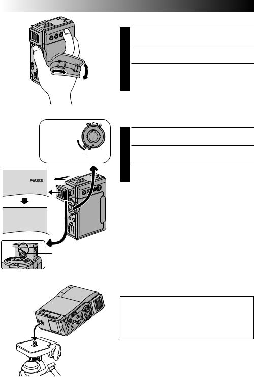
Grip Adjustment |
|
1 Loosen the belt. |
|
Pass your right hand through the loop and grasp the |
|
2 grip. |
|
Adjust your thumb and fingers through the grip, to |
|
3 easily operate the Recording Start/Stop button and |
|
Power Switch and Power Zoom (SHUTTLE SEARCH) |
|
Ring. Be sure to tighten the belt to your preference. |
Power 
Switch

Lock Button
Viewfinder Adjustment
1 Set the Power Switch to “ ” or “
 ” while pressing down the Lock Button located on the switch.
2 Pull out the viewfinder fully.
3 Turn the Dioptre Adjustment Control until the indications in the viewfinder are clearly focused.
PAUSE
|
Tripod Mounting |
||
Dioptre Adjustment |
|
|
|
1 |
|
|
|
Control |
|
Align the screw on the tripod with the camera’s |
|
|
|
mounting socket. Then tighten the screw. |
|
|
|
|
•Some tripods are not equipped with studs. |
CAUTION:
When attaching the camera to a tripod, extend its legs to stabilise the camcorder. It is not advised to use small sized tripods. This may cause damage to the unit by falling over.
SET/SELECT Button MENU Button
+, – Button
Power lamp
Power Switch
Lock Button
Display
 W IPE / FADER OF F

 PROGRAM AE

 W. BALANCE
 CAMERA
 MANUAL
 SYSTEM
 D I SPLAY
 DSC
DSC
END
|
|
ON SCREEN |
|
– |
|
DISPLAY Menu |
|
|
|
|
|
||||
|
|
|
LCD / TV |
||||
|
|
|
DATE / T I ME |
|
– |
AUTO |
|
|
|
|
T I ME CODE |
|
– |
OFF |
|
|
|
|
CLOCK |
|
|
2 0 . 12 |
. 01 |
|
|
|
ADJ . |
|
|
17 |
: 3 0 |
|
|
|
|
|
|
|
|
RETURN
|
|
CLOCK |
|
|
|
|
|
|
|
|
|
|
|
|
|
|
|
|
|
|
|
|
|
|
|
|
|
2 0 |
. 12 |
. 01 |
|
|
|
ADJ . |
|
|
|
17 |
: 3 0 |
|
|
|
|
|
|
|
|
|
|
|
|
|
|
|
|
|
|
|
|
|
|
|
|
EN13
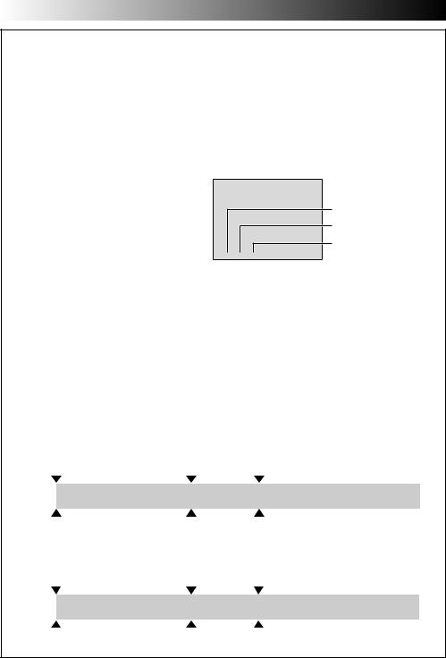
Date/Time Settings
The date/time is recorded onto the tape at all times, but its display can be turned on or off during playback
( pg. 44, 45).
1 Set the Power Switch to “ ” while pressing down the Lock Button located on the switch, then open the LCD monitor fully or pull out the viewfinder fully. The power lamp lights and the camcorder is turned on.
2 Press MENU. The Menu Screen appears.
3 Press + or – to select “ DISPLAY”, and press SET/ SELECT. The DISPLAY Menu appears.
4 Press + or – to select “CLOCK ADJ.”, and press SET/ SELECT. “Day” is highlighted.
Press + or – to input the day, and press SET/SELECT. Repeat to input the month, year, hour and minute. Press + or – to select “ RETURN”, and press SET/ SELECT twice. The Menu Screen closes.
Built-in Clock’s Rechargeable Lithium Battery
To store the date/time in memory, the clock’s rechargeable lithium battery is integrated in the camcorder. While the camcorder is connected to an AC outlet using the AC Power Adapter/Charger, or while the battery pack attached to the camcorder continues to supply power, the clock’s rechargeable lithium battery is always charged. However, if the camcorder is not used for approx. 3 months, the clock’s lithium battery will become discharged and the date/time stored in memory will be lost. When this occurs, first connect the camcorder to an AC outlet using the AC Power Adapter/Charger for over 24 hours to charge the clock’s rechargeable lithium battery. Then perform the date/time setting before using the camcorder.
Note that the camcorder can be used without setting the date/time.
NOTE:
Even if you select “CLOCK ADJ.”, if the parameter is not highlighted the camcorder’s internal clock continues to operate. Once you move the highlight bar to the first date/time parameter (day), the clock stops. When you finish setting the minute and press SET/SELECT, the date and time begin operation from the date and time you have just set.
14 EN |
GETTING STARTED (cont.) |
|
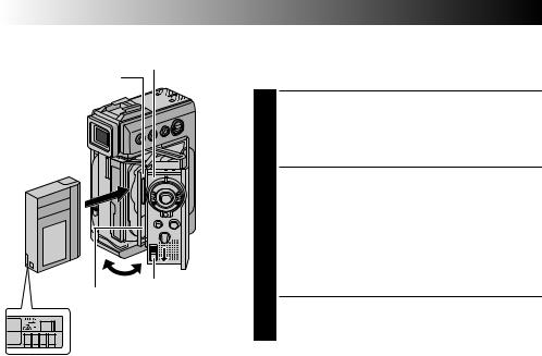
Loading/Unloading A Cassette |
Cassette holder cover |
The camcorder needs to be powered up to load or eject a |
|
|
|
|
Cassette holder |
|
cassette. |
|
|
Slide down and hold OPEN/EJECT in the direction |
|
|
1 of the arrow then pull the cassette holder cover |
|
|
open until it locks. The cassette holder opens |
Make sure the |
|
automatically. |
window side is |
|
•Do not touch internal components. |
facing out. |
|
Insert or remove a tape and press “PUSH HERE” to |
|
|
|
|
|
2 close the cassette holder. |
|
|
•Once the cassette holder is closed, it recedes |
|
|
automatically. Wait until it recedes completely |
|
|
before closing the cassette holder cover. |
|
|
•When the battery’s charge is low, you may not be |
|
|
able to close the cassette holder cover. Do not |
|
|
apply force. Replace the battery with a fully |
PUSH HERE |
OPEN/EJECT |
charged one before continuing. |
Switch |
|
|
|
Close the cassette holder cover firmly until it locks |
|
|
|
|
Erase protection tab* |
3 into place. |
|
|
||
|
|
Approximate recording time |
* To Protect Valuable Recordings . . .
.... slide the erase protection tab on the back of the tape in the direction of “SAVE”. This prevents the tape from being recorded over. To record on this tape, slide the tab back to “REC” before loading it.
Be sure to press only the section labeled “PUSH HERE” to close the cassette holder; touching other parts may cause your finger to get caught in the cassette holder, resulting in injury or product damage.
NOTES:
Tape |
|
Recording mode |
|
|
|
|
|
SP |
|
LP |
|
|
|
||
30 min. |
30 min. |
|
45 min. |
|
|
|
|
60 min. |
60 min. |
|
90 min. |
|
|
|
|
80 min. |
80 min. |
|
120 min. |
|
|
|
|
●It takes a few seconds for the cassette holder to open. Do not apply force.
●If you wait a few seconds and the cassette holder does not open, close the cassette holder cover and try again. If the cassette holder still does not open, turn the camcorder off then on again.
●If the tape does not load properly, open the cassette holder cover fully and remove the cassette. A few minutes later, insert it again.
●When the camcorder is suddenly moved from a cold place to a warm environment, wait a short time before opening the cassette holder cover.
●Closing the cassette holder cover before the cassette holder comes out may cause damage to the camcorder.
●Even when the camcorder is switched off, a cassette can be loaded or unloaded. After the cassette holder is closed with the camcorder switched off, however, it may not recede. It is recommended to turn the power on before loading or unloading.
●When resuming recording, once you open the cassette holder cover a blank portion will be recorded on the tape or a previously recorded scene will be erased (recorded over) regardless of whether the cassette holder came out or not. See page 22 for information about recording from the middle of a tape.
SET/SELECT Button MENU Button
+, – Button
Power lamp
Power Switch
Lock Button
Display
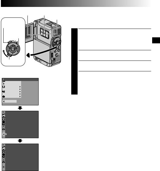
CAMERA Menu
|
REC MODE |
– |
SP |
|
|||
|
|
|
LP |
 Sub Menu
EN15
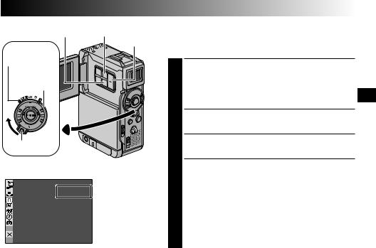
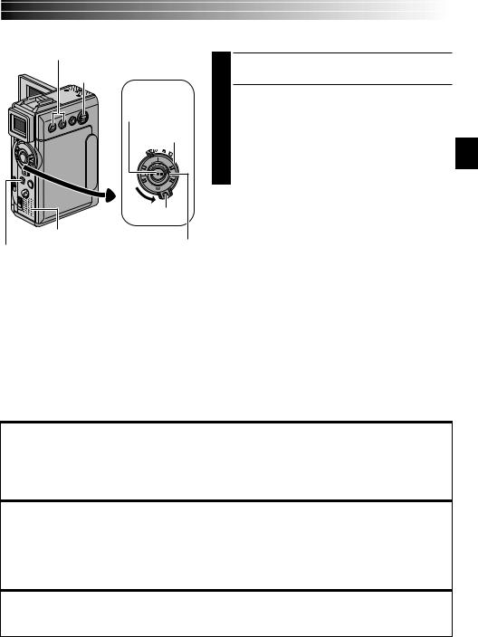
Recording Mode Setting
Set the tape recording mode depending on your preference.
1 Set the Power Switch to “ ” while pressing down the Lock Button located on the switch, then open the LCD monitor fully or pull out the viewfinder fully. The power lamp lights and the camcorder is turned on.
2 Press MENU. The Menu Screen appears.
3 Press + or – to select “ CAMERA” and press SET/ SELECT. The CAMERA Menu appears.
4 Press + or – to select “REC MODE” and press SET/ SELECT. The Sub Menu appears. Select “SP” or “LP” by pressing + or – and press SET/SELECT. Press + or
– to select “ RETURN”, and press SET/SELECT twice. The Menu Screen closes.
•Audio Dubbing ( pg. 66) and Insert Editing ( pg. 68) are impossible on a tape recorded in the LP mode.
•“LP” (Long Play) is more economical, providing 1.5 times the recording time.
NOTES:
●If the recording mode is switched during recording, the playback picture will be blurred at the switching point.
●It is recommended that tapes recorded in the LP mode on this camcorder be played back on this camcorder.
●During playback of a tape recorded on another camcorder, blocks of noise may appear or there may be momentary pauses in the sound.
16 EN
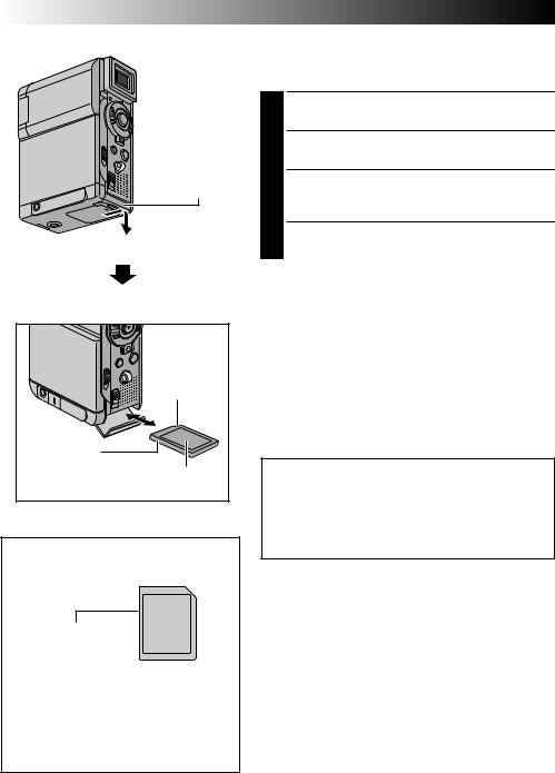
Card Cover
Clipped edge |
Memory card |
Label |
To Protect Valuable Files (available only for SD Memory Card) . . .
Write protection tab
... slide the write protection tab on the side of the memory card in the direction of “LOCK”. This prevents the memory card from being recorded over. To record on this memory card, slide the tab back to the position opposite to “LOCK” before loading it.
GETTING STARTED (cont.)
Loading A Memory Card
The provided memory card is already inserted in the camcorder when you receive the camcorder.
1 Make sure the camcorder’s power is off.
2 Open the card cover (MEMORY CARD).
3 Insert the memory card firmly clipped edge first.
•Do not touch the terminal on the reverse side of the label.
4 Close the card cover.
To Unload A Memory Card . . .
.... in step 3 push the memory card, then the memory card comes out of the camcorder automatically. Pull it out and close the card cover.
NOTES:
●Be sure to use only SD Memory Cards marked “
 ” or MultiMediaCards marked “


 ”.
”.
●Some brands of memory cards are not compatible with this camcorder. Before purchasing a memory card, consult its manufacturer or dealer.
●Before using a new memory card, it is necessary to FORMAT the card. pg. 38
ATTENTION:
Do not insert/remove the memory card while the camcorder is turned on, as this may cause the memory card to be corrupted or cause the camcorder to become unable to recognise whether or not the card is installed.
MENU Button
SET/SELECT Button |
+, – Button |
Power Switch
Lock Button |
|
Display |
|
QUAL I TY – |
DSC Menu |
F I NE |
|
S I ZE |
STANDARD |
EN17
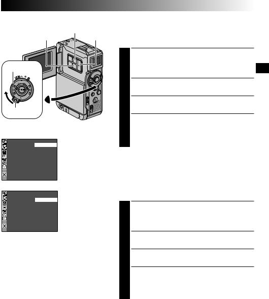
Picture Quality Mode Setting
The Picture Quality mode can be selected to best match your needs. Two Picture Quality modes are available: FINE and STANDARD (in order of quality).
1 Set the Power Switch to “ ” while pressing down the Lock Button located on the switch, then open the LCD monitor fully or pull out the viewfinder fully. The power lamp lights and the camcorder is turned on.
2 Press MENU. The Menu Screen appears.
3 Press + or – to select “  DSC” and press SET/ SELECT. The DSC Menu appears.
4 Press + or – to select “QUALITY” and press SET/ SELECT. The Sub Menu appears. Press + or – to select the desired mode and press SET/SELECT. Press + or – to select “ RETURN”, and press SET/SELECT twice. The Menu Screen closes.
Image Size Mode Setting
I MAGE SIZE – VGA
XGA
NOTES:
●The number of storable images depends on the selected picture quality as well as the composition of the subjects in the images and the type of memory card being used.
●In the XGA mode, images are shot in 720 x 576 pixels and they are converted and stored in the XGA mode file size (1024 x 768 pixels).
Approximate Number of Storable Images
The Image Size mode can be selected to best match your needs. Two Image Size modes are available: XGA (1024 x 768 pixels) and VGA (640 x 480 pixels) (in order of quality).
1 Set the Power Switch to “ ” while pressing down the Lock Button located on the switch, then open the LCD monitor fully or pull out the viewfinder fully. The power lamp lights and the camcorder is turned on.
2 Press MENU. The Menu Screen appears.
3 Press + or – to select “  DSC” and press SET/ SELECT. The DSC Menu appears.
4 Press + or – to select “IMAGE SIZE” and press SET/ SELECT. The Sub Menu appears. Press + or – to select the desired mode and press SET/SELECT. Press + or – to select “ RETURN”, and press SET/SELECT twice. The Menu Screen closes.
Image Size/Picture |
|
MultiMediaCard |
|
SD Memory Card |
|
||||
|
|
|
|
|
|
|
|
|
|
Quality Mode |
|
|
|
|
|
|
|
|
|
8MB* |
|
16MB* |
32MB* |
8MB** |
8MB* |
16MB* |
32MB* |
64MB* |
|
|
|
||||||||
XGA FINE |
24 |
|
49 |
100 |
16 |
20 |
46 |
97 |
195 |
|
|
|
|
|
|
|
|
|
|
XGA STANDARD |
74 |
|
150 |
305 |
51 |
62 |
140 |
295 |
610 |
|
|
|
|
|
|
|
|
|
|
VGA FINE |
53 |
|
105 |
215 |
37 |
44 |
100 |
210 |
435 |
|
|
|
|
|
|
|
|
|
|
VGA STANDARD |
150 |
|
310 |
630 |
105 |
125 |
290 |
610 |
1255 |
|
|
|
|
|
|
|
|
|
|
* Optional
** Provided (12 sound effects pre-stored)
18 EN
To turn on the camcorder, set the Power Switch to any operation mode except “OFF” while pressing down the Lock Button located on the switch.
VIDEO/MEMORY
Switch
Power lamp
Power Switch
Lock Button
When the Power Switch is set to “ ”,
”,
“ ” appears. When set to “ ” or “ ”, there is no indication.
When the Power Switch is set to “ ” or
” or
“ ” and the VIDEO/MEMORY Switch is set to “MEMORY”, the selected image size (“VGA” or “XGA”) is displayed. When set to “VIDEO”, there is no indication.
VGA
GETTING STARTED (cont.)
Operation Mode
Choose the appropriate operation mode according to your preference using the Power Switch and VIDEO/ MEMORY Switch.
Power Switch Position
 (Manual):
Allows you to set various recording functions using the Menus. If you want more creative capabilities than Full Auto recording, try this mode.
 (Full Auto):
Allows you to record using NO special effects or manual adjustments. Suitable for standard recording.
OFF:
Allows you to switch off the camcorder.
 :
:
•Allows you to play back a recording on the tape.
•Allows you to display a still image stored in the memory card or to transfer a still image stored in the memory card to a computer.
VIDEO/MEMORY Switch Position
VIDEO:
Allows you to record on a tape or play back a tape. If “REC SELECT” is set to “
 /
/
 ” in the DSC Menu Screen, still images are also recorded in the memory card.
MEMORY:
Allows you to record a still image or display a still image stored in the memory card.

VIDEO RECORDING & PLAYBACK |
EN19 |
|||
|
VIDEO RECORDING |
|
|
|
|
& |
|
|
|
|
PLAYBACK |
|
|
|
|
CONTENTS |
|
|
|
|
VIDEO RECORDING |
20 – 22 |
|
|
|
|
|
||
|
Basic Recording |
20 |
|
|
|
||||
|
Journalistic Shooting ........................................................ |
21 |
|
|
|
Interface Shooting .......................................................... |
21 |
|
|
|
Zooming ...................................................................... |
21 |
|
|
|
Time Code .................................................................... |
22 |
|
|
|
Recording From The Middle Of A Tape .................................. |
22 |
|
|
|
VIDEO PLAYBACK .............................................. |
23 – 26 |
|
|
|
Normal Playback ............................................................ |
23 |
|
|
|
Still Playback ................................................................ |
23 |
|
|
|
Shuttle Search ............................................................... |
23 |
|
|
|
Connections ......................................................... |
24 – 25 |
|
|
|
Blank Search ................................................................. |
26 |
|
|
|
|
|
|
|

20 EN
Power Lamp
VIDEO/MEMORY
Switch
Recording Start/
Stop Button
Power Switch
Lock Button
Display
25min Tape remaining time indicator (Approximate)
min  90 min
  89 min
  3 min
3 min
(Now calculating)
0 min 1 min
1 min 2 min
2 min
(Blinking) (Blinking) (Blinking)
Tally lamp (Lights while recording is in progress)
Lens Cover (Slide up |
|
|
the lens cover to |
|
|
protect the lens |
|
|
when the camcorder |
Lock Button |
|
is not in use.) |
||
|
BR I GHT
180 |
° |
90° |
MONITOR BRIGHT |
+/– Button |
|||
|
|
|
VIDEO RECORDING
Basic Recording
NOTE:
You should already have performed the procedures listed below. If not, do so before continuing.
●Power ( pg. 10)
●Grip Adjustment ( pg. 12)
●Viewfinder Adjustment ( pg. 12)
●Load A Cassette ( pg. 14)
●Recording Mode Setting ( pg. 15)
1 Slide down the lens cover while pressing down the Lock Button located on the cover.
2 Set the VIDEO/MEMORY Switch to “VIDEO”, then set the Power Switch to “ ” or “
 ” while pressing down the Lock Button located on the switch.
Shooting while using the LCD monitor: Make sure the viewfinder is pushed back in. Open the LCD monitor fully.
Shooting while using the viewfinder: Make sure the LCD monitor is closed and locked. Pull out the viewfinder fully.
•Be sure to pull out the viewfinder until you hear a click, otherwise it may be pushed back in during use.
•The Power lamp lights and the camcorder enters the Record-Standby mode. “PAUSE” is displayed.
Press the Recording Start/Stop Button. “ |
” |
3 appears while recording is in progress. |
|
To Stop Recording . . .
.... press the Recording Start/Stop Button. The camcorder re-enters the Record-Standby mode.
To Adjust The Brightness Of The Display
.... press MONITOR BRIGHT + or – until the bright level indicator on the display moves and the appropriate brightness is reached.
•It is also possible to adjust the brightness of the viewfinder.
NOTES:
●The image will not appear simultaneously on the LCD monitor and the viewfinder except during Interface Shooting.
●If the Record-Standby mode continues for 5 minutes, the camcorder’s power shuts off automatically. To turn the camcorder on again, push back and pull out the viewfinder again or close and re-open the LCD monitor.
●When a blank portion is left between recorded scenes on the tape, the time code is interrupted and errors may occur when editing the tape. To avoid this, refer to “Recording From The Middle Of A Tape” ( pg. 22).
●When sliding down the lens cover, be sure not to touch the lens.
●To turn the tally lamp or beep sounds off, pg. 40, 42.
For other notes, pg. 77

EN21
Journalistic Shooting
In some situations, different shooting angles may provide more dramatic results. Hold the camcorder in the desired position and tilt the LCD monitor in the most convenient direction. It can rotate 270° (90° downward, 180° upward).
Interface Shooting
|
The person you shoot can view himself/herself in the LCD monitor, and |
|
you can even shoot yourself while viewing your own image in the LCD |
|
monitor. |
|
Open the LCD monitor and tilt it upward to 180° so that it faces forward. |
|
When the LCD monitor is tilted upward to an angle of over approx. 105°, |
|
the monitor image is inverted vertically. If the viewfinder is pulled out at |
|
that time, it also switches on. |
Self-Recording |
Point the lens toward the subject (yourself when self-recording) and start |
|
recording. |
|
During Interface Shooting, the monitor image and indications do not |
|
appear inverted as they would when viewing a mirror. |
|
|
|
|
|
|
|
FEATURE: Zooming |
|
|
|
|
|
|
|
PURPOSE: |
|
|
|
|
|
|
|
To produce the zoom in/out effect, or an instantaneous |
|
|
|
|
|
|
|
change in image magnification. |
Zoom in (T: Telephoto) |
|
|
OPERATION: |
||||
|
|
|
|
|
|
|
Zoom In |
1 xW |
T |
|
1 0 xW |
T |
|
|
Turn the Power Zoom (SHUTTLE SEARCH) Ring anti- |
|
|
|
|
20xW |
T |
|
clockwise. |
|
|
|
|
|
40xW |
T |
Zoom Out |
|
|
|
|
|
|
|
|
|
|
|
|
|
|
|
Turn the Power Zoom (SHUTTLE SEARCH) Ring |
|
|
|
|
|
|
|
clockwise. |
|
|
|
|
|
|
|
The further you turn the Power Zoom Ring the |
|
|
|
Zoom out (W: Wide angle) |
|
quicker the zoom action. |
||
|
|
|
|
NOTES: |
|||
|
|
Zoom display |
|
|
|||
|
|
|
|
● Focusing may become unstable during Zooming. In |
|||
|
|
|
|
|
|
|
|
1 0 x |
W |
T |
|
|
|
this case, set the zoom while in Record-Standby, |
|
|
|
|
lock the focus by using the manual focus |
||||
|
|
|
|
|
Digital zoom zone |
||
|
|
|
|
|
( pg. 53), then zoom in or out in Record mode. |
||
●Zooming is possible to a maximum of 100X, or it can be switched to 10X magnification using the
10X (optical) zoom |
optical zoom ( pg. 41). |
zone |
● Zoom magnification of over 10X is done through |
|
|
|
Digital image processing, and is therefore called |
Approximate zoom ratio |
Digital Zoom. |
● During Digital zoom, the quality of image may |
|
|
suffer. |
|
● Digital zoom cannot be used in the following cases: |
|
•When digital image processing, such as Picture |
|
Wipe/Dissolve ( pg. 50, 51) or Video Echo |
Power Zoom |
( pg. 49), is activated. |
Ring |
● Macro shooting (as close as approx. 5 cm to the |
|
subject) is possible when the Power Zoom Ring is |
|
turned all the way clockwise. Also see “TELE |
|
MACRO” in the Menu Screen on page 41. |
For other notes, pg. 77
22 EN |
VIDEO RECORDING (cont.) |
Time Code
During recording, a time code is recorded on the tape. This code is to confirm the location of the recorded scene on the tape during playback.
If recording starts from a blank portion, the time code begins counting from “00:00:00” (minute:second:frame). If recording starts from the end of a previously recorded scene, the time code continues from the last time code number.
To perform Random Assemble Editing ( pg. 69 – 73), time code is necessary. If during recording a blank portion is left partway through the tape, the time code is interrupted. When recording is resumed, the time code starts counting up again from “00:00:00”. This means the camcorder may record the same time codes as those existing in a previously recorded scene. To prevent this, perform “Recording From The Middle of A Tape” below in the following cases;
•When shooting again after playing back a recorded tape.
•When power shuts off during shooting.
•When a tape is removed and re-inserted during shooting.
•When shooting using a partially recorded tape.
•When shooting on a blank portion located partway through the tape.
•When shooting again after shooting a scene then opening/closing the cassette holder cover.
Display
 12 : 34 : 24
Frames are not displayed during recording.
Minutes
Seconds
Frames
(25 frames = 1 second)
Recording From The Middle Of A Tape
1.Play back a tape or use Blank Search ( pg. 26) to find the spot at which you want to start recording, then engage the Still Playback mode ( pg. 23).
2.Set the Power Switch to “ ” or “
 ” while pressing down the Lock Button located on the switch, then start recording.
NOTES:
●The time code cannot be reset.
●During fast-forwarding and rewinding, the time code indication does not move smoothly.
●The time code is displayed only when “TIME CODE” is set to “ON” ( pg. 43, 44).
When a blank portion is recorded on a tape
Time code |
|
|
Time code |
Time code |
|
|||
00:00:00 |
|
|
05:43:21 |
00:00:00 |
|
|||
|
|
|
|
|
|
|
|
|
Tape |
|
Already recorded scene |
|
Blank |
|
|
Newly recorded scene |
|
|
|
|
|
|
|
|||
Shooting start point |
Shooting stop point |
Shooting start point |
||||||
Proper recording |
|
|
|
|
|
|
||
Time code |
|
|
Time code |
Time code |
|
|||
00:00:00 |
|
|
05:43:21 |
05:44:00 |
|
|||
|
|
|
|
|
|
|
||
Tape |
|
Already recorded scene |
|
New scene |
|
Latest scene |
||
|
|
|
|
|
|
|
|
|
Shooting start point |
Shooting start point |
Shooting start point |
VIDEO PLAYBACK
VOL. +/–
VIDEO/MEMORY
Switch
Play/Pause
Button (4/6)
Power Switch
|
Lock Button |
|
Speaker |
|
|
Stop Button (5) |
SHUTTLE SEARCH |
|
Ring (2/3) |
||
|
EN23
Normal Playback
1 Load a tape ( pg. 14).
2Set the VIDEO/MEMORY Switch to “VIDEO”, then set the Power Switch to “ ” while pressing down the Lock Button located on the switch. To start playback, press 4/6.
•To stop playback, press 5.
•Turn the SHUTTLE SEARCH Ring anti-clockwise (2) and release to rewind, or clockwise (3) and release to fast-forward the tape during Stop mode.
To Control The Speaker Volume . . .
.... press VOL. + to turn up the volume, or – to turn down the volume.
NOTES:
●If Stop mode continues for 5 minutes when power is supplied
from a battery, the camcorder shuts off automatically. To turn on again, set the Power Switch to “OFF”, then to “ ”.
”.
●The playback picture can be viewed in the LCD monitor, viewfinder or on a connected TV ( pg. 24, 25).
●You can also view the playback picture on the LCD monitor with it flipped over and pushed against the camera body.
●LCD monitor/viewfinder indications:
•When power is supplied from a battery: the “ ” battery pack remaining power indicator is displayed. When power is supplied from an AC outlet: “
 ” does not appear.
•During Stop mode, none of the indications are displayed.
●When a cable is connected to the AV connector, the sound is not heard from the speaker.
Still Playback: Pauses during playback.
1)Press 4/6during playback.
2)To resume normal playback, press 4/6again.
●If still playback continues for more than about 3 minutes, the camcorder’s Stop mode is automatically engaged. After 5 minutes in the Stop mode, the camcorder’s power is automatically turned off.
●When 4/6is pressed, the image may not pause immediately while the camcorder stabilises the still image.
Shuttle Search: Allows high-speed search in either direction.
1)During playback, turn the SHUTTLE SEARCH Ring clockwise (3) and release for forward or anticlockwise (2) and release for reverse search.
2)To resume normal playback, press 4/6.
●During playback, turn the SHUTTLE SEARCH Ring clockwise (3) or anti-clockwise (2) and hold it. The search continues as long as you hold the ring. Once you release it, normal playback resumes.
●A slight mosaic effect appears on screen during Shuttle Search. This is not a malfunction.
Slow-Motion Playback, Frame-By-Frame Playback, Playback Zoom and
Playback Special Effects
Available only with the remote control (provided) ( pg. 64, 65).
24EN |
VIDEO PLAYBACK (cont.) |
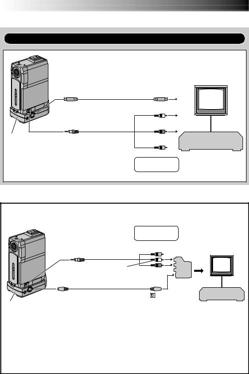
Connections
Use the provided Audio/Video cable and optional S-Video cable.
|
|
S-Video cable |
To TV or VCR |
|
|
To S-VIDEO OUT |
To S-VIDEO IN |
|
|||
(optional) |
|
TV |
|||
|
|
|
|
White to |
|
|
|
|
|
|
|
|
|
|
|
AUDIO L IN* |
|
|
Audio/Video cable |
|
Red to |
|
|
|
[mini-plug to RCA |
|
|
||
To AV OUT |
plug] (provided) |
|
AUDIO R IN* |
|
|
Docking |
|
|
|
Yellow to |
VCR |
Station** |
|
|
|
VIDEO IN |
|
* The Audio cable is not required for watching still |
|
p |
|
||
When the S-Video |
|
||||
images only. |
|
|
|
||
|
|
cable is not used. |
|
||
** Refer to “Docking Station Attachment” ( pg. 25). |
|
||||
|
|
|
|||
If your TV/VCR has a 21-pin connector
Use the provided Cable Adapter.
|
When the S-Video |
|
|
|
cable is not used. |
|
|
Audio/Video cable |
p |
Cable |
|
Yellow |
|||
[mini-plug to RCA plug] |
Adapter |
||
|
|||
To AV OUT (provided) |
|
|
|
White to |
Red to |
|
|
AUDIO L* |
|
||
|
AUDIO R* |
|
To TV or VCR
TV |
To S-VIDEO OUT
S-Video cable (optional)
Docking Station**
*The Audio cable is not required for watching still images only.
** Refer to “Docking Station Attachment” ( pg. 25).
|
|
|
|
VCR |
|
|
|
|
|
|
|
|
|
|
To -IN “Y/C”/“ |
CVBS” |
|||
|
|
Video Out |
|
|
|
|
Select Switch |
|
|
NOTE:
Set the video out select switch of the cable adapter as required:
Y/C : When connecting to a TV or VCR which accepts Y/C signals and uses an S-Video cable. CVBS : When connecting to a TV or VCR which does not accept Y/C signals and uses an audio/video
cable.
EN25
1 Make sure all units are turned off.
2Connect the camcorder to a TV or VCR as shown in the illustration ( pg. 24).
If using a VCR . . . go to step 3. If not . . . go to step 4.
3Connect the VCR output to the TV input, referring to your VCR’s instruction manual.
4 Turn on the camcorder, the VCR and the TV.
5Set the VCR to its AUX input mode, and set the TV to its VIDEO mode.
To choose whether or not the following displays appear on the connected TV . . .
•Date/Time
.... set “DATE/TIME” to “AUTO”, “ON” or “OFF” in the Menu Screen ( pg. 44, 45).
•Time Code
.... set “TIME CODE” to “ON” or “OFF” in the Menu Screen ( pg. 44, 45).
•Playback Sound Mode, Tape Speed And Tape Running Displays for video playback
Or
Type of file, Directory/File Names and Image Number/Total Number of Images for D.S.C. Playback
.... set “ON SCREEN” to “LCD” or “LCD/TV” in the Menu Screen ( pg. 44, 45).
Or, press DISPLAY on the remote control.
NOTES:
●It is recommended to use the AC Power Adapter/ Charger as the power supply instead of the battery pack ( pg. 11).
●To monitor the picture and sound from the
camcorder without inserting a tape or memory
card, set the camcorder’s Power Switch to “ ” or “
 ”, then set your TV to the appropriate input mode.
●Make sure you adjust the TV sound volume to its minimum level to avoid a sudden burst of sound when the camcorder is turned on.
●If you have a TV or speakers that are not specially shielded, do not place the speakers adjacent to the TV as interference will occur in the camcorder playback picture.
●While the Audio/Video cable is connected to the AV connector, sound cannot be heard from the speaker.
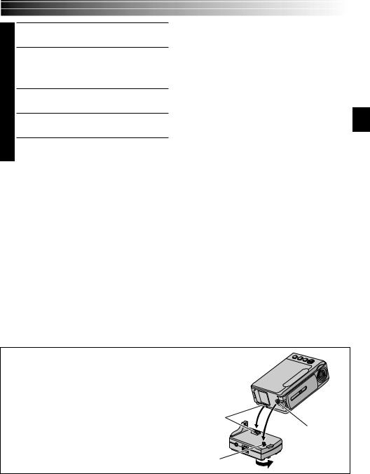
Docking Station Attachment
First align the multi connector and screw on the Docking Station with the camcorder’s multi connector and tripod mounting socket and tighten the screw.
When removing the camcorder, loosen the screw and detach the camcorder.
Multi connector
NOTE:
While the Docking Station is attached to the camcorder, it is not possible to load and unload the memory card. Also, connecting and disconnecting the DV cable are not possible.
Tripod mouting socket
Screw
26EN
FOCUS/BLANK Button |
VIDEO/MEMORY Switch |
Power Switch
Lock Button
Stop Button (5)
Display
44
BLANK SEARCH
VIDEO PLAYBACK (cont.)
Blank Search
Helps you find where you should start recording in the middle of a tape to avoid time code interruption
( pg. 22).
1 Load a tape ( pg. 14).
2Set the VIDEO/MEMORY Switch to “VIDEO”, then set the Power Switch to “ ” while pressing down the Lock Button located on the switch.
3Press FOCUS/BLANK.
•“BLANK SEARCH” appears blinking and the camcorder automatically starts reverse or forward shuttle search, then stops at the spot which is about 3 seconds of tape before the beginning of the detected blank portion.
To cancel Blank Search midway . . .
.... press 5.
NOTES:
●In step 3, if the current position is at a blank portion the camcorder searches in the reverse direction, and if the current position is at a recorded portion the camcorder searches in the forward direction.
●Blank Search does not work if “HEAD CLEANING REQUIRED. USE CLEANING CASSETTE” has appeared with the tape.
●If the beginning or end of the tape is reached during Blank Search, the camcorder stops automatically.
●A blank portion which is shorter than 5 seconds of tape may not be detected.
●The detected blank portion may be located between recorded scenes. Before you start recording, make sure there is no recorded scene after the blank portion.

DIGITAL STILL CAMERA(D.S.C.) RECORDING & PLAYBACK EN27
DIGITAL STILL CAMERA (D.S.C.)
RECORDING
&
PLAYBACK
CONTENTS |
|
D.S.C. RECORDING ............................................. |
28 – 29 |
Basic Shooting (Snapshot) ........................................ |
28 – 29 |
D.S.C. PLAYBACK ............................................... |
30 – 38 |
Normal Playback (Of Images) ............................................ |
30 |
Auto Playback (Of Images) ................................................ |
30 |
Index Screen ................................................................. |
31 |
Index Playback .............................................................. |
32 |
Jump Playback ............................................................... |
32 |
Protecting Files .............................................................. |
33 |
Deleting Files ........................................................ |
34 – 35 |
Setting Print Information (DPOF Setting) ...................... |
36 – 37 |
Initialising A Memory Card ............................................ |
38 |

28 EN |
D.S.C. RECORDING |
VIDEO/MEMORY
Switch
Power Switch
Lock Button
SNAPSHOT Button
Display
CAMERA Menu
SNAP MODE – P I N–UP
FRAME
FULL
MULT I – 4
MULT I – 9
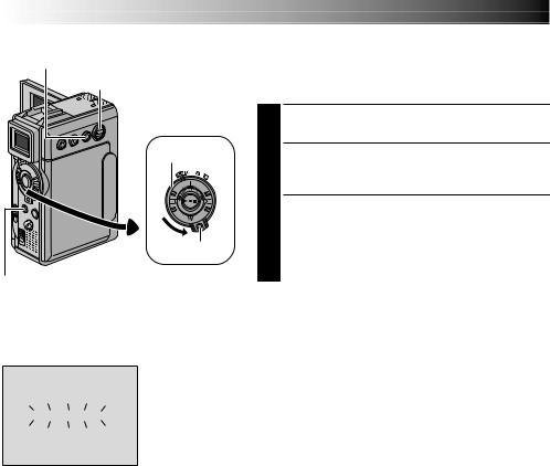
Basic Shooting (Snapshot)
You can use your camcorder as a Digital Still Camera for taking snapshots.
NOTE:
You should already have performed the procedures listed below. If not, do so before continuing.
●Power ( pg. 10)
●Grip Adjustment ( pg. 12)
●Viewfinder Adjustment ( pg. 12)
●Loading A Memory Card ( pg. 16)
●Picture Quality/Image Size Mode Setting ( pg. 17)
SNAPSHOT MODE SELECTION
1Slide down the lens cover while pressing down the Lock Button located on the cover. Set the VIDEO/ MEMORY Switch to “MEMORY”, then set the Power Switch to “ ” while pressing down the Lock Button located on the switch. Open the LCD monitor fully or pull out the viewfinder fully.
2 Press MENU. The Menu Screen appears.
3Press + or – to select “ CAMERA”, then press SET/ SELECT. The CAMERA Menu appears.
4Press + or – to select “SNAP MODE”, then press
SET/SELECT.
5Press + or – to select the desired Snapshot mode, then press SET/SELECT. Press + or – to select
“ RETURN” and press SET/SELECT twice. The Menu Screen closes.
SNAPSHOT RECORDING
Image Size mode |
1 |
|
Press SNAPSHOT. |
appears while the snapshot |
||||||||||
Displays the Image Size mode of the stored |
|
is being taken. |
|
|||||||||||
image. There are 2 modes available: XGA and |
|
|
The image is stored in the memory card. |
|||||||||||
VGA ( pg. 17). |
|
|
•Regardless of the Power Switch position (“ ” or |
|||||||||||
|
|
|
Display |
|
|
“ ”), Snapshot recording takes place using the |
||||||||
|
|
|
|
|
||||||||||
|
|
|
|
|
selected Snapshot mode. |
|||||||||
|
|
|
|
|
|
|
|
|
|
|
|
|
||
|
VGA |
F I NE |
|
|
|
|
|
|
||||||
|
|
|
|
|
|
|||||||||
|
|
|
|
|
|
10 / 100 |
|
Picture Quality mode |
|
|||||
|
|
|
|
|
|
|
|
|
|
|
||||
|
|
|
|
|
|
|
|
|
|
|
||||
|
|
|
|
|
|
|
|
|
|
Displays the Picture Quality mode of the stored image. There are 2 modes |
||||
|
|
|
|
|
|
|
|
|
|
available: FINE and STD (Standard) ( pg. 17). |
|
|||
|
|
|
|
|
|
|
|
|
|
Total number of shots |
|
|||
|
|
|
|
|
|
|
|
|
|
|
||||
|
|
|
|
|
|
|
|
|
|
Displays the approximate total number of shots that can be stored, including |
||||
|
|
|
|
|
|
|
|
|
|
those already taken. The number increases or decreases depending on the shots |
||||
|
|
|
|
|
|
|
|
|
|
stored, the Picture Quality/Image Size mode, etc. |
|
|||
|
|
|
|
|
|
|
|
|
|
|
|
|
|
|
Number of shots taken
Displays the number of images that have already been shot.
Card icon
Appears during shooting and blinks when a memory card is not loaded.
Shooting icon
Appears and blinks during shooting.
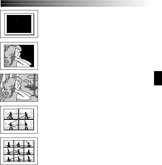
PIN-UP
Pin-Up mode*
FRAME Snapshot mode with frame*
FULL Snapshot mode with no frame*
MULTI-4
Multi-Analyzer 4
MULTI-9
Multi-Analyzer 9
*There is the sound effect of a shutter closing.
EN29
To Delete Unwanted Still Images . . .
.... when unwanted still images are stored in the memory card or its memory is full, refer to “Deleting Files” ( pg. 34) and delete unwanted still images.
To Remove The Shutter Sound . . .
.... when you do not want to hear the shutter sound, set “BEEP” to “OFF” in the Menu Screen ( pg. 40, 42). The sound is no longer heard from the speaker.
NOTES:
●Even if “MULTI-4” or “MULTI-9” is engaged, Snapshot recording will be performed in the FULL mode during Digital Zoom or Night-Scope ( pg. 48).
●The image is stored in the VGA mode regardless of the image size mode setting ( pg. 17) if “MULTI-4” or “MULTI-9” is engaged.
●If SNAPSHOT is pressed when “DIS” is set to “ON” ( pg. 41), the Stabiliser will be disabled.
●If Snapshot recording is not possible, “ 

 ” blinks when SNAPSHOT is pressed.
●If Program AE with special effects ( pg. 48) is engaged, certain modes of Program AE with special effects are disabled during Snapshot recording. In such a case, the icon blinks.
●If shooting is not performed for approx. 5 minutes when the Power Switch is set to “ ” or “
 ” and power is supplied from the battery pack, the camcorder shuts off automatically to save power. To perform shooting again, push back and pull out the viewfinder again or close and re-open the LCD monitor.
●The Motor Drive mode ( pg. 52) is disabled when the VIDEO/MEMORY Switch is set to “MEMORY”.
●When a cable is connected to the AV connector, the shutter sound is not heard from the speaker, however it is recorded onto the tape.
●Still images taken are compliant to DCF (Design rules for Camera File systems). They do not have any compatibility with devices which are not compliant to DCF.
●In the XGA mode, images are shot in 720 x 576 pixels and they are converted and stored in the XGA mode file size (1024 x 768 pixels).
30 EN |
D.S.C. PLAYBACK |
VIDEO/MEMORY
Switch
Play/Pause
Button (4/6)
Power Switch
|
Lock Button |
|
Stop Button (5) |
SHUTTLE SEARCH Ring |
|
(2/3) |
||
|
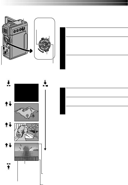
Normal Playback (Of Images)
Images shot with the camcorder are automatically numbered, then stored in numerical order in the memory card. You can view the stored images, one at a time, much like flipping through a photo album.
1 Load a memory card ( pg. 16).
2Set the VIDEO/MEMORY Switch to “MEMORY”, then set the Power Switch to “ ” while pressing down the Lock Button. Open the LCD monitor fully or pull out the viewfinder fully.
•A stored image is displayed.
3Turn the SHUTTLE SEARCH Ring clockwise (3) to display the next image.
Turn the SHUTTLE SEARCH Ring anti-clockwise (2) to display the previous image.
[For Normal Playback] |
[For Auto Playback] |
Auto Playback (Of Images) |
|||||
To display the next image |
|||||||
|
|
Display |
|
You can run through all the images stored in memory |
|||
|
|
|
100-0010 |
|
automatically. |
||
|
|
|
|
|
1 Perform steps 1 and 2 above. |
||
10 |
/ |
24 |
10.10.01 |
|
2 |
Press 4/6to start Auto Playback. |
|
|
|
|
100-0011 |
|
|
||
|
|
|
|
|
3 To end Auto Playback, press 5. |
||
|
|
|
|
|
NOTES: |
||
11 |
/ |
24 |
10.10.01 |
|
● Even if you shoot a new image after playing back a |
||
|
|
|
100-0012 |
|
low-numbered one, this will not overwrite an existing |
||
|
|
|
|
|
image, because new images are automatically stored |
||
|
|
|
|
|
after the last-recorded one. |
||
|
|
|
|
|
● Images shot in a file size other than VGA/XGA with |
||
|
|
|
|
|
devices that are compatible with DCF (Design rules for |
||
12 |
/ |
24 |
10.10.01 |
|
Camera File systems) will be displayed as reduced-size |
||
|
thumbnail images. These thumbnail images cannot be |
||||||
|
|
|
100-0013 |
|
|||
|
|
|
|
transferred to a PC. |
|||
|
|
|
|
|
|||
|
|
|
|
|
● Images shot with devices that are not compatible with |
||
|
|
|
|
|
DCF cannot be viewed with this camcorder; “Unsup- |
||
|
|
|
|
|
ported file!” will be displayed. |
||
13 |
/ |
24 |
10.10.01 |
|
|
|
|
|
Total number of |
|
|
|
|||
|
images |
|
|
|
|
||
To display the |
Displays the total |
Directory and File names |
|||||
previous image |
number of stored |
||||||
Displays the directory and file names ( pg. 31). |
|||||||
|
images. |
|
|||||
|
|
|
|
|
|||
Image number |
|
Date |
|
|
|||
Displays the index |
|
|
|
||||
|
Displays the date when the image was shot (if “DATE/TIME”is |
||||||
number of the image file |
|||||||
set to “ON” in the Menu Screen pg. 44 – 45). |
|||||||
( pg. 31). |
|
|
|||||
|
|
|
|
|
|||
Loading...