


COMPACT VHS CAMCORDER
GR-SXM38U
INSTRUCTIONS
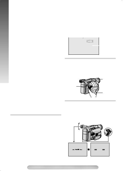
AUTOMATIC DEMONSTRATION
Automatic Demonstration takes place when “DEMO MODE” is set to “ON” (factory-preset).
•Available when the Power Switch is set to “ ” or “
 ”.
”.
•To cancel Automatic Demonstration, set “DEMO MODE” to “OFF” ( pg. 15).
For Customer Use:
Enter below the Model No. and Serial No. which
is located on the bottom of the camcorder.
Retain this information for future reference.
Model No.
Serial No.
CONTENTS
GETTING STARTED |
|
5 ~ 9 |
RECORDING/PLAYBACK |
9 |
~ 10 |
|
|
|
BASIC FEATURES |
10 |
~ 12 |
|
|
|
MENU SETTINGS |
12 |
~ 16 |
|
|
|
TERMS |
|
24 |
|
|
|
Dear Customer,
Thank you for purchasing the JVC Compact VHS camcorder. Before use, please read “SAFETY PRECAUTIONS” ( pg. 3, 4) to ensure safe use of this product.
ENGLISH
LYT1518-001B
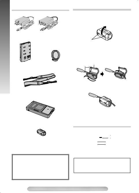
ACCESSORIES |
PROVIDED ACCESSORIES |
|
|
PROVIDED |
AC Adapter AP-V14U or |
|
AP-V18U |
Battery Pack |
Lens Cap |
|
|
BN-V10U |
|
Shoulder Strap
Cassette Adapter
C-P8U
Core filter (for S-
Video cable)
QQR0491-002 or
QQR1417-002
NOTE:
In order to maintain optimum performance of the camcorder, provided cables may be equipped with one or more core filter. If a cable has only one core filter, the end that is closest to the filter should be connected to the camcorder.
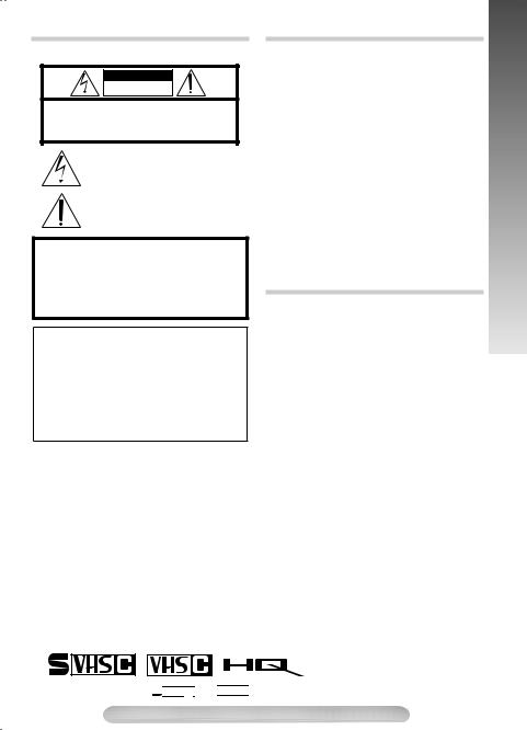
How To Attach The Core filter
Attach the core filters to the cables. The core filter reduces interference.
1) Release the stoppers on both ends of the core filter.
Stopper
2) Run the cable through the core filter, leaving approx. 3 cm of cable between the cable plug and the core filter.
Wind the cable once around the outside of the core filter as shown in the illustration.
Core filter
3 cm
Wind once
3) Close the core filter until it clicks shut.
NOTES:
•Take care not to damage the cable.
•When connecting a cable, attach the end with the core filter to the camcorder.
OPTIONAL ACCESSORIES
•Battery Packs BN-V12U, BN-V20U, BNV400U
•Compact S-VHS (
 ) Cassettes ST- C-40/30/20
•Compact VHS (


 ) Cassettes TC-40/ 30/20
•Active Carrying Bag CB-V75
•A/V (Audio/Video) Cable
•S-Video Cable
Some accessories are not available in some areas.
Please consult your nearest JVC dealer for details on accessories and their availability.
2
SAFETY PRECAUTIONS
CAUTION
RISK OF ELECTRIC SHOCK
DO NOT OPEN
CAUTION: TO REDUCE THE RISK OF ELECTRIC SHOCK, DO NOT REMOVE COVER (OR BACK).
NO USER-SERVICEABLE PARTS INSIDE.
REFER SERVICING TO QUALIFIED SERVICE PERSONNEL.
The lightning flash with arrowhead symbol, within an equilateral triangle, is intended to alert the user to the presence of uninsulated "dangerous voltage" within the product’s enclosure that may be of sufficient magnitude to constitute a risk of electric shock to persons.
The exclamation point within an equilateral triangle is intended to alert the user to the presence of important operating and maintenance (servicing) instructions in the literature accompanying the appliance.
WARNING:
TO REDUCE THE RISK OF FIRE OR ELECTRIC SHOCK, DO NOT EXPOSE THIS APPARATUS TO RAIN OR MOISTURE.
This product has a fluorescent lamp that contains a small amount of mercury. Disposal of these materials may be regulated in your community due to environmental considerations.
For disposal or recycling information please contact your local authorities, or the Electronics Industries Alliance:
<http://www.eiae.org>
Only cassettes marked 

 and
and 


CAUTIONS
•This camcorder is designed to be used with NTSC-type color television signals. It cannot be used for playback with a television of a different standard. However, live recording and LCD monitor/viewfinder playback are possible anywhere.
•Use the JVC BN-V10U/V12U/V20U/V400U battery packs and, to recharge them or to supply power to the camcorder from an AC outlet, use the provided multi-voltage AC Adapter.
(An appropriate conversion adapter may be necessary to accommodate different designs of AC outlets in different countries.)
NOTES:
•The rating plate (serial number plate) and safety caution are on the bottom and/or the back of the main unit.
•The rating information and safety caution of the AC Adapter are on its upper and lower sides.
ATTENTION
The product that you have purchased is powered by a rechargeable battery. The battery is recyclable. At the end of its useful life, under various state and local laws, it may be illegal to dispose of this battery into the municipal waste stream. Check with your local solid waste officials for details in your area for recycling options or proper disposal.
can be used with this camcorder.
SAFETY PRECAUTIONS
3
SAFETY PRECAUTIONS
The EPA certified RBRC® Battery Recycling Seal on the nickel-cadmium (Ni-Cd) battery indicates JVC is voluntarily participating in an industry program to collect and recycle these batteries at the end of their useful life, when taken out of service in the United States. The RBRC® program provides a convenient alternative to placing used Ni-Cd batteries into the trash or the municipal waste stream, which may be illegal in your area. Please call 1-800-8-BATTERY™ for information on Ni-Cd battery recycling and disposal bans/restrictions in your area. JVC’s involvement in this program is part of our commitment to preserving our environment and conserving our natural resources.
When the equipment is installed in a cabinet or on a shelf, make sure that it has sufficient space on all sides to allow for ventilation (10 cm (3-15/16") or more on both sides, on top and at the rear).
Do not block the ventilation holes.
(If the ventilation holes are blocked by a newspaper, or cloth etc. the heat may not be able to get out.) No naked flame sources, such as lighted candles, should be placed on the apparatus.
When discarding batteries, environmental problems must be considered and the local rules or laws governing the disposal of these batteries must be followed strictly.
The apparatus shall not be exposed to dripping or splashing. Do not use this equipment in a bathroom or places with water.
Also do not place any containers filled with water or liquids (such as cosmetics or medicines, flower vases, potted plants, cups etc.) on top of this unit.
(If water or liquid is allowed to enter this equipment, fire or electric shock may be caused.)
IMPORTANT SAFETY INSTRUCTIONS
1)Read these instructions.
2)Keep these instructions.
3)Heed all warnings.
4)Follow all instructions.
5)Do not use this apparatus near water.
6)Clean only with dry cloth.
7)Do not block any ventilation openings. Install in accordance with the manufacturer’s instructions.
8)Do not install near any heat sources such as radiators, heat registers, stoves, or other apparatus (including amplifiers) that produce heat.
9)Only use attachments/accessories specified by the manufacturer.
10)Use only with the cart, stand,
tripod, bracket, or table specified by the manufacturer, or sold with the apparatus. When a cart is used, use
caution when moving the cart/apparatus combination to avoid injury from tip-over.
11)Unplug this apparatus during lightning storms or when unused for long periods of time.
12)Refer all servicing to qualified service personnel. Servicing is required when the apparatus has been damaged in any way, such as power-supply cord or plug is damaged, liquid has been spilled or objects have fallen into the apparatus, the apparatus has been exposed to rain or moisture, does not operate normally, or has been dropped.
4

CONTROLS, CONNECTORS AND INDICATORS
Refer to this diagram while reading the instructions.
Eyepiece 51 2 3 4
During
shooting
% & ( )
6
7 |
|
8 |
|
5 |
|
9 |
|
! |
" # $ |
Keep the lens |
|
cap attached to |
|
the camcorder |
|
Cassette holder |
~ |
|
45° |
Connector Cover |
|
|
|
|
|
|
|
|
|
|
|
|
Viewfinder |
180° |
90° |
, |
|
|
|
|||
|
|
|
|
|
|
|
|
Speaker |
|
|
Turn the gear |
|
|
|
|
to take up |
|
|
|
|
|
|
|
|
|
|
|
|
slack |
|
|
|
|
+ |
|
|
|
|
LCD monitor |
. Erase |
|
|
|
|
|
|
|
- |
|
|
|
|
protection tab |
|
|
|
|
|
|
|
Video Light |
Microphone |
|
|
|
|
|
|
|
|
|
LCD Monitor/Viewfinder Indications
During Recording During Playback
|
|
/ :;< = |
> |
|
|
? |
|
|
@ |
|
1 2 0M I N |
A S –ET T 3 0 |
|
|
|
|
|
|
REC SP |
|
|
|
0V |
|
|
|
[ |
|
|
+0 2 |
|
|
|
||
\] |
|
S –VHS REC |
MWB |
|
1 |
|
|
|
^ |
_ |
5M I N |
PAUSE |
1 / 2S |
|
2 |
1X |
|
} |
– – – – – – – – |
+ |
3 |
|
|
|||
|
BR I GHT |
– – – |
|
|
||||
{ |
| |
CONGRATULAT I ONS |
|
|
|
|
||
|
DEC 25 . 05 AM 11 : 4 5 : 18 |
|
b |
a |
||||
|
|
|
|
|
|
|
||
4 5 6 7 89 !
S–ET |
SP |
TBC |
– 1 : 2 3 : 4 5 |
|
AT |
|
|
|
|
|
|
|
|
|
" |
|
VOLUME – |
––––– |
|
|
|
––––– + |
|
|
|
pg. 17 for “Warning Indications”
GETTING STARTED
5

GETTING STARTED
1 |
• |
MENU Wheel [–, +] .............................. |
|
pg. 8 |
|
• |
BRIGHT Wheel [–, +] ......................... |
|
pg. 15 |
|
• |
Speaker Volume Control [VOL.] ......... |
pg. 10 |
|
|
• TRACKING Wheel [–, +]..................... |
|
pg. 10 |
|
2 |
5- Second Recording Button |
|
||
|
|
[5 SEC. REC]...................................... |
|
pg. 10 |
3Power Zoom Lever [T/W] ...................... |
|
pg. 10 |
||
4 |
• Manual Focus Button [ |
FOCUS].... |
pg. 10 |
|
|
• Time Base Corrector Button [TBC]..... |
pg. 11 |
||
5Shoulder Strap Eyelets........................... |
|
pg. 9 |
||
6S-Video Output Connector [S].............. |
pg. 11 |
|||
7Audio Output Connector [A].................. |
|
pg. 11 |
||
8Video Output Connector [V] |
................. |
pg. 11 |
||
9Battery Release Switch |
|
|
||
|
[BATTERY RELEASE]............................ |
|
pg. 7 |
|
!DC IN Connector .................................... |
|
pg. 7 |
||
"• Recording Start/Stop Button ................ |
pg. 9 |
|||
|
• REFRESH Button................................. |
|
pg. 7 |
|
#Lock Button............................................. |
|
pg. 8 |
||
$Power Switch [PLAY, OFF, |
, ].... pg. 7, 8, 9 |
|||
%POWER/CHARGE Lamp........................ |
|
pg. 7 |
||
&• Retake Forward Button [RETAKE F] .. |
pg. 10 |
|||
|
• Fast-Forward Button [F]........................ |
|
pg. 9 |
|
(• Play/ Pause Button............................... |
|
pg. 9 |
||
|
• Backlight Compensation Button ......... |
pg. 10 |
||
)• Stop Button [STOP].............................. |
|
pg. 9 |
||
|
• Eject [EJECT] Button ........................... |
|
pg. 9 |
|
~• Retake Rewind Button [RETAKE R] ... |
pg. 10 |
|||
|
• Quick Review Button [ |
R].............. |
pg. 10 |
|
|
• Rewind Button [R] ................................ |
|
pg. 9 |
|
+Close Button........................................... |
|
pg. 9 |
||
,Diopter Adjustment Control .................... |
|
pg. 8 |
||
-Grip Strap ............................................... |
|
pg. 8 |
||
.Tripod Mounting Socket .......................... |
|
pg. 9 |
||
/Tape Remaining Time........................... |
|
pg. 15 |
||
:Recording Mode Indicator .................... |
|
pg. 14 |
||
;Video Light Indicator............................. |
|
pg. 13 |
||
<Backlight Compensation Indicator ........ |
pg. 10 |
|||
=Recording Format Indicator (S/ S-ET)....... |
pg. 16 |
|||
>Tape Length Indicator ........................... |
pg. 15 |
|||
?Zoom Indicator Bar ............................... |
pg. 10 |
|||
|
a Zoom Level Indicator |
|
||
|
b Approximate Zoom Ratio |
|
||
@Recording Indicator................................. |
pg. 9 |
|||
[Digital Effect Indicator ........................... |
pg. 13 |
|||
\Program AE Indicator............................ |
pg. 13 |
|||
]Fade/Wipe-Standby Indicator................ |
pg. 13 |
|||
^Picture Stabilizer Indicator .................... |
pg. 14 |
|||
_• Interval Time/Recording Time Indicator .. |
pg. 15 |
|||
|
• 5 Sec. Rec Mode Indicator.................. |
pg. 10 |
||
{Instant Title Display ............................... |
pg. 14 |
|||
|Date/Time Display................................. |
pg. 15 |
|||
}Bright Level Indicator ............................ |
pg. 15 |
|||
VFocus Indicator...................................... |
pg. 10 |
|||
0Exposure Control Level Counter ........... |
pg. 13 |
|||
1White Balance Mode Indicator .............. |
pg. 14 |
|||
2S-VHS/S-VHS ET Recording Indicator..... |
pg. 16 |
|||
3Record-Standby Mode Indicator ............. |
pg. 9 |
|||
4 |
|
|
: Cassette Indicator |
pg. 15 |
|
|
|||
5TBC Indicator ........................................ |
pg. 11 |
|||
6Recording Format Indicator (S/S-ET)........ |
pg. 15 |
|||
7Tape Counter ........................................ |
pg. 16 |
|||
8Recording Mode Indicator (SP/EP)....... |
pg. 14 |
|||
9Tape Running Indicator |
|
|||
|
3: Playback |
|
||
|
¡: Fast-Forward/ Shuttle Search |
|
||
|
1: Rewind/ Shuttle Search |
|
||
|
8: Pause |
|
||
!Tracking Indicator .................................. |
pg. 10 |
|||
"VOLUME: Speaker Volume Indicator......... |
pg. 10 |
|||
6
GETTING STARTED
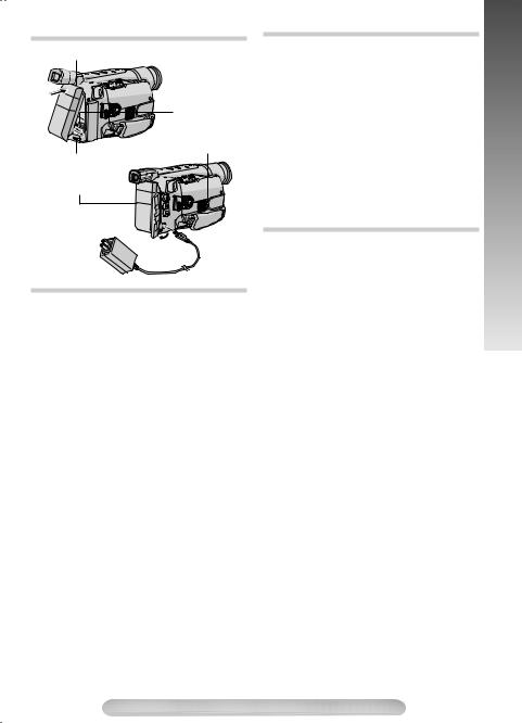
Hook on
Push in
Power Switch
BATTERY RELEASE
Switch
Battery pack
To AC outlet
To DC IN connector
AC Adapter
Charging the Battery Pack
1) Hook the end of the battery pack to the camcorder and push the battery in until it locks in place.
•If the battery pack is attached wrongly, a malfunction may occur.
2)Set the Power Switch $ to “OFF” while pressing down the Lock Button #. Connect the AC Adapter to the DC IN connector !, then plug the AC Adapter to the AC Outlet.
3)The CHARGE lamp % blinks to indicate charging.
4)When the CHARGE lamp % stops blinking and turns off, charging is finished. Unplug the AC Adapter from the AC outlet. Disconnect the AC Adapter from the camcorder.
To Detach The Battery Pack…
… slide BATTERY RELEASE 9 and pull out the battery pack.
Battery Pack |
Charging time |
BN-V10U |
approx. 1 hr. 30 min. |
|
|
BN-V12U (optional) |
approx. 1 hr. 40 min. |
|
|
BN-V20U (optional) |
approx. 2 hrs. 40 min. |
|
|
BN-V400U (optional) |
approx. 5 hrs. 10 min. |
|
|
Charging time is for a fully discharged battery pack.
Using the Battery Pack
Perform step 1) of “Charging the Battery Pack”.
Approximate recording time (unit: min.)
Battery Pack |
Viewfinder on |
LCD monitor on |
|
|
|
BN-V10U |
95 |
80 |
|
(50) |
(45) |
|
|
|
BN-V12U |
100 |
85 |
(optional) |
(55) |
(50) |
|
|
|
BN-V20U |
160 |
140 |
(optional) |
(85) |
(80) |
|
|
|
BN-V400U |
380 |
330 |
(optional) |
(210) |
(195) |
|
|
|
( ): When the video light is on.
Using AC Power
Connect the AC Adapter to the camcorder ( step 2) of “Charging the Battery Pack”).
•The provided AC Adapter features automatic voltage selection in the AC range from 110V to 240V.
ATTENTION:
Before detaching the power source, make sure that the camcorder’s power is turned off. Failure to do so can cause the camcorder to malfunction.
REFRESH:
Be sure to fully discharge a battery pack before recharging or storing it for a long period of time, otherwise the battery performance will be reduced.
1)Perform steps 1) through 3) of “Charging the Battery Pack”.
2)Press REFRESH " for over 4 seconds. The CHARGE lamp % blinks faster to indicate discharging.
3)When discharging is finished, charging automatically starts and the CHARGE lamp % blinks normally.
GETTING STARTED
7
GETTING STARTED
STORE BATTERY:
Be sure to fully discharge a battery pack by performing the following steps before storing it for a long period af time, otherwise the battery performance will be reduced.
1)Attach the battery to the camcorder with no cassette inserted.
2)Set the Power Switch $ to “ ” or “
 ” while pressing down the Lock Button #.
•During charging or discharging, the camcorder cannot be operated.
•Charging and discharging are not possible if the wrong type of battery is used.
•When charging the battery pack for the first time or after a long storage period, the CHARGE lamp % may not light. Remove the battery pack from the camcorder, then try charging again.
•If a fully-charged battery’s operation time remains extremely short, the battery is worn out. Please purchase a new one.
•Perform charging where the temperature is between 10°C and 35°C (50°F and 95°F). 20°C to 25°C (68°F to 77°F) is the ideal temperature range. If the environment is too cold, charging may be incomplete.
•Charging time varies according to the ambient temperature and the status of the battery pack.
•Since the AC Adapter processes electricity internally, it becomes warm during use. Be sure to use it only in well-ventilated areas.
•The following operation stops charging or discharging:
•Set the Power Switch $ to “PLAY”, “ ” or “
 ”.
”.
•Disconnect AC Adapter from the AC outlet.
•Detach the battery from the camcorder.
•Using the optional AA-V15 AC Power Adapter/Charger, you can charge the BN-V10U/V12U/V20U/V400U battery pack without the camcorder.
However, it cannot be used as an AC adapter.
•To avoid interference with reception, do not use the AC Adapter near a radio.
•Recording time is reduced significantly when Zoom or Record-Standby mode is engaged repeatedly or the LCD monitor is used repeatedly.
•Before extended use, it is recommended that you prepare enough battery packs to cover 3 times the planned shooting time.
Date/Time Settings
1)Set the Power Switch $ to “ ” while pressing down the Lock Button #.
2)Press the MENU Wheel 1 in. The TOP MENU Screen appears.
3)Rotate the MENU Wheel 1 to select “3TO SYSTEM MENU” and press it.
4)Rotate the MENU Wheel 1 to select “3DATE/ TIME SET” and press it. The DATE/TIME SET Menu appears.
5)To set “YEAR”, “MONTH”, “DAY” or “TIME” (hour/ minute), rotate the MENU Wheel 1 to select the
desired item, and press it. When the setting begins blinking, rotate the MENU Wheel 1 until the correct setting appears and then press it. The setting stops blinking.
6)When none of these settings (“YEAR”, “MONTH”, “DAY”, “TIME”) blinks, rotate the MENU Wheel 1 to select “3RETURN” and press it, to go to Menu Screen.
7)Press the MENU Wheel 1 in to select “3EXIT” to close the Menu Screen.
•To display the date and time in the camcorder’s display and on a connected TV, see DATE/TIME DISP. ( pg. 15) in SYSTEM MENU.
•The date/time cannot be stored in memory if the built-in clock battery runs out. Consult an authorised JVC dealer for replacement, or set the date/time as necessary before you start shooting.
|
|
|
|
|
|
12-hour |
|
|
|
D A T E |
T I M E S E T |
|
indication with |
||
|
|
|
|
|
|
AM or PM |
|
|
Y E A R |
H |
2 0 0 6 |
||||
|
M O N T |
|
6 |
|
|
|
|
|
D A Y |
2 8 |
|
|
|
||
|
T I M E |
PM 8 : 2 0 |
|
|
|
||
|
|
|
|
||||
 R E T URN
Grip Adjustment
1)Separate the Velcro strip.
2)Pass your right hand through the loop and grasp the grip.
3)Adjust so that your thumb and fingers can easily operate the Recording Start/Stop Button " and Power Zoom Lever 3. Refasten the Velcro strip.
3
"
Velcro strip
Viewfinder Adjustment
1)Set the Power Switch $ to “ ” or “
 ” while pressing down the Lock Button #.
2)Make sure the LCD monitor is closed and locked. Pull up the viewfinder and adjust it manually to get the best view.
3)Turn the Diopter Adjustment Control , until the indications in the viewfinder are clearly focused.
45°
, |
PAU SE
8
 Loading...