


DIGITAL VIDEO CAMERA
GR-DVX PRO
ENGLISH
Please visit our CyberCam Homepage on the World Wide Web and answer our Consumer Survey (in English only):
http://www.jvc-victor.co.jp/index-e.html
For Customer Use:
Enter below the Model No. and Serial No. which is located on the bottom of cabinet. Retain this information for future reference.
Model No.
INSTRUCTIONS
Serial No.
LYT0002-0W1A EN

2

 EN
EN


Dear Customer,
Thank you for purchasing this Digital Video Camera. Before use, please read the safety information and precautions contained in the following pages to ensure safe use of this product.
Using This Instruction Manual
•All major sections and subsections are listed in the Table Of Contents (Z pg. 9).
•Notes appear after most subsections. Be sure to read these as well.
•Basic and advanced features/operation are separated for easier reference.
It is recommended that you . . .
...... refer to “Controls, Indications and Connectors” (Z pgs. 75 – 80) and familiarize yourself with button locations, etc. before use.
...... read thoroughly the Safety Precautions and Safety Instructions that follow. They contain extremely important information regarding the safe use of your new camcorder.
You are recommended to carefully read the cautions on pages 81 and 82 before use.
SAFETY PRECAUTIONS
CAUTION
RISK OF ELECTRIC SHOCK
DO NOT OPEN
CAUTION: TO REDUCE THE RISK OF ELECTRIC SHOCK.
DO NOT REMOVE COVER (OR BACK). NO USER-SERVICEABLE PARTS INSIDE.
REFER SERVICING TO QUALIFIED SERVICE PERSONNEL.
The lightning flash with arrowhead symbol, within an equilateral triangle, is intended to alert the user to the presence of uninsulated "dangerous voltage" within the product's enclosure that may be of sufficient magnitude to constitute a risk of electric shock to persons.
The exclamation point within an equilateral triangle is intended to alert the user to the presence of important operating and maintenance (servicing) instructions in the literature accompanying the appliance.
The AA-V90U AC Power Adapter/Charger should be used with:
AC 120 V`, 60 Hz in the USA and Canada, AC 110 – 240 V`, 50/60 Hz in other countries.
CAUTION (applies to the AA-V90U)
TO PREVENT ELECTRIC SHOCK MATCH WIDE BLADE OF PLUG TO WIDE SLOT, FULLY INSERT.
ATTENTION (s'applique à l'AA-V90U)
POUR ÉVITER LES CHOCS ÉLECTRIQUES, INTRODUIRE LA LAME LA PLUS LARGE DE LA FICHE DANS LA BORNE CORRESPONDANTE DE LA PRISE ET POUSSER JUSQU'AU FOND.
WARNING:
TO PREVENT FIRE OR SHOCK HAZARD, DO NOT EXPOSE THIS UNIT TO RAIN OR MOISTURE.
Warning on lithium cell battery (for remote control unit)
The battery used in this device may present a fire or chemical burn hazard if mistreated. Do not recharge, disassemble, heat above 100°C (212°F) or incinerate.
Replace battery with Panasonic (Matsushita Electronic), Sanyo or Maxell CR2025; use of another battery may present a risk of fire or explosion.
nDispose of used battery properly.
nKeep away from children.
nDo not disassemble and do not dispose of in fire.
CAUTION (applies to the Docking Station):
TO REDUCE THE RISK OF FIRE,
DO NOT REMOVE COVER (OR
BACK). NO USER–SERVICEABLE
PARTS INSIDE. REFER SERVICING TO QUALIFIED SERVICE PERSONNEL.
NOTES:
cThe rating plate (serial number plate) and safety caution are on the bottom and/or the back of the main unit.
cThe rating plate (serial number plate) of the AC Power Adapter/Charger is on its bottom.
cThe rating plate (serial number plate) of the Docking Station is on its bottom.
This Class B digital apparatus meets all requirements of the Canadian Interference – Causing Equipment Regulations.
“Cet appareil numérique de la classe B respecte toutes les exigences du Règlement sur le matériel brouilleur du Canada.”
This camcorder is designed to be used with NTSCtype color television signals. It cannot be used for playback with a television of a different standard.
However, live recording and LCD monitor/ viewfinder playback are possible anywhere. Use the BN-V907U battery pack and, to recharge it, the provided multi-voltage AC Power Adapter/Charger AA-V90U. (An appropriate conversion adapter may be necessary to accommodate different designs of AC outlets in different countries.)

IMPORTANT PRODUCT SAFETY INSTRUCTIONS
Electrical energy can perform many useful functions. But improper use can result in potential electrical shock or fire hazards. This product has been engineered and manufactured to assure your personal safety. In order not to defeat the built-in safeguards, observe the following basic rules for its installation, use and servicing.
ATTENTION:
Follow and obey all warnings and instructions marked on your product and its operating instructions. For your safety, please read all the safety and operating instructions before you operate this product and keep this manual for future reference.
INSTALLATION
1. Grounding or Polarization
(A)Your product may be equipped with a polarized alternating-current line plug (a plug having one blade wider than the other). This plug will fit into the power outlet only one way. This is a safety feature.
If you are unable to insert the plug fully into the outlet, try reversing the plug. If the plug should still fail to fit, contact your electrician to replace your obsolete outlet. Do not defeat the safety purpose of the polarized plug.
(B)Your product may be equipped with a 3-wire grounding-type plug, a plug having a third (grounding) pin. This plug will only fit into a grounding-type power outlet. This is a safety feature.
If you are unable to insert the plug into the outlet, contact your electrician to replace your obsolete outlet. Do not defeat the safety purpose of the grounding-type plug.
2. Power Sources
Operate your product only from the type of power source indicated on the marking label. If you are not sure of the type of power supply to your home, consult your product dealer or local power company. If your product is intended to operate from battery power, or other sources, refer to the operating instructions.
3. Overloading
Do not overload wall outlets, extension cords, or integral convenience receptacles as this can result in a risk of fire or electric shock.
4. Power Cord Protection
Power supply cords should be routed so that they are not likely to be walked on or pinched by items placed upon or against them, paying particular attention to cords at plugs, convenience receptacles, and the point where they exit from the product.
EN 3
5. Ventilation
Slots and openings in the cabinet are provided for ventilation. To ensure reliable operation of the product and to protect it from overheating, these openings must not be blocked or covered.
•Do not block the openings by placing the product on a bed, sofa, rug or other similar surface.
•Do not place the product in a built-in installation such as a bookcase or rack unless proper ventilation is provided or the manufacturer’s instructions have been adhered to.
6. Wall or Ceiling Mounting
The product should be mounted to a wall or ceiling only as recommended by the manufacturer.
ANTENNA INSTALLATION
INSTRUCTIONS
1. Outdoor Antenna Grounding
If an outside antenna or cable system is connected to the product, be sure the antenna or cable system is grounded so as to provide some protection against voltage surges and built-up static charges. Article 810 of the National Electrical Code, ANSI/NFPA 70, provides information with regard to proper grounding of the mast and supporting structure, grounding of the lead-in wire to an antenna discharge unit, size of grounding conductors, location of antenna discharge unit, connection to grounding electrodes, and requirements for the grounding electrode.
2. Lightning
For added protection for this product during a lightning storm, or when it is left unattended and unused for long periods of time, unplug it from the wall outlet and disconnect the antenna or cable system. This will prevent damage to the product due to lightning and power-line surges.
3. Power Lines
An outside antenna system should not be located in the vicinity of overhead power lines or other electric light or power circuits, or where it can fall into such power lines or circuits. When installing an outside antenna system, extreme care should be taken to keep from touching such power lines or circuits as contact with them might be fatal.
EXAMPLE OF ANTENNA GROUNDING AS PER
NATIONAL ELECTRICAL CODE, ANSI/NFPA 70
|
ANTENNA |
|
LEAD IN WIRE |
GROUND CLAMP |
|
|
ANTENNA |
|
DISCHARGE UNIT |
|
(NEC SECTION |
ELECTRIC SERVICE |
810-20) |
EQUIPMENT |
GROUNDING |
|
|
|
CONDUCTORS |
|
(NEC SECTION 810-21) |
|
GROUND CLAMPS |
POWER SERVICE GROUNDING ELECTRODE SYSTEM |
|
(NEC ART 250. PART H) |
|
NEC – NATIONAL ELECTRICAL CODE |
|

4

 EN
EN


USE
1. Accessories
To avoid personal injury:
•Do not place this product on an unstable cart, stand, tripod, bracket or table. It may fall, causing serious injury to a child or adult, and serious damage to the product.
•Use only with a cart, stand, tripod, bracket, or table recommended by the manufacturer or sold with the product.
•Use a mounting accessory recommended by the manufacturer and follow the manufacturer’s instructions for any mounting of the product.
•Do not try to roll a cart with small casters across thresholds or deep-pile carpets.
2. Product and Cart Combination
A product and cart combination should be moved with care. Quick stops, excessive force, and uneven surfaces may cause the product and cart combination to overturn.
3. Water and Moisture
Do not use this product near water—for example, near a bath tub, wash bowl, kitchen sink or laundry tub, in a wet basement, or near a swimming pool and the like.
PORTABLE CART WARNING (Symbol provided by RETAC)
4. Object and Liquid Entry
Never push objects of any kind into this product through openings as they may touch dangerous voltage points or short-out parts that could result in a fire or electric shock. Never spill liquid of any kind on the product.
5. Attachments
Do not use attachments not recommended by the manufacturer of this product as they may cause hazards.
6. Cleaning
Unplug this product from the wall outlet before cleaning. Do not use liquid cleaners or aerosol cleaners. Use a damp cloth for cleaning.
7. Heat
SERVICING
1. Servicing
If your product is not operating correctly or exhibits a marked change in performance and you are unable to restore normal operation by following the detailed procedure in its operating instructions, do not attempt to service it yourself as opening or removing covers may expose you to dangerous voltage or other hazards. Refer all servicing to qualified service personnel.
2. Damage Requiring Service
Unplug this product from the wall outlet and refer servicing to qualified service personnel under the following conditions:
a.When the power supply cord or plug is damaged.
b.If liquid has been spilled, or objects have fallen into the product.
c.If the product has been exposed to rain or water.
d.If the product does not operate normally by following the operating instructions. Adjust only those controls that are covered by the operating instructions as an improper adjustment of other controls may result in damage and will often require extensive work by a qualified technician to restore the product to its normal operation.
e.If the product has been dropped or damaged in any way.
f.When the product exhibits a distinct change in performance—this indicates a need for service.
3. Replacement Parts
When replacement parts are required, be sure the service technician has used replacement parts specified by the manufacturer or have the same characteristics as the original part. Unauthorized substitutions may result in fire, electric shock or other hazards.
4. Safety Check
Upon completion of any service or repairs to this product, ask the service technician to perform safety checks to determine that the product is in safe operating condition.
The product should be situated away from heat sources such as radiators, heat registers, stoves, or other products (including amplifiers) that produce heat.
SAFETY PRECAUTIONS
Do not point the lens or the viewfinder directly into the sun. This can cause eye injuries, as well as lead to the malfunctioning of internal circuitry. There is also a risk of fire or electric shock.
CAUTION! The following notes concern possible physical damage to the camcorder and to the user.
When carrying, be sure to always attach and use the provided hand strap. Hold the camcorder firmly in your hand, with the strap securely around your wrist. Carrying or holding the camcorder by the viewfinder and/or the LCD monitor can result in dropping the unit, or in a malfunction.
Take care not to get your finger caught in the cassette cover. Do not let children operate the camcorder, as they are particularly susceptible to this type of injury.
Do not use a tripod on unsteady or unlevel surfaces. It could tip over, causing serious damage to the camcorder.
CAUTION! Attaching the camcorder to the Docking Station, connecting cables (AUDIO/VIDEO, S-VIDEO, Editing, DC) and leaving the unit on top of the TV is not recommended, as tripping on the cables will cause the camcorder to fall, resulting in damage.
nThis camcorder is designed exclusively for
the 
 digital video cassette. Only cassettes marked
 can be used with this unit.
Before recording an important scene . . .
..... make sure you only use cassettes with the Mini DV mark.
..... remember that this camcorder is not compatible with other digital video formats.
..... remember that this camcorder is intended for private consumer use only. Any commercial use without proper permission is prohibited. (Even if you record an event such as a show, performance or exhibition for personal enjoyment, it is strongly recommended that you obtain permission beforehand.)
EN 5
About Batteries
DANGER! Do not attempt to take the batteries apart, or expose them to flame or excessive heat, as there is a risk of fire or explosion.
WARNING! Do not allow the battery terminals, or the battery itself, to come in contact with metals, as this can result in a short circuit and possibly start a fire.
•When transporting, make sure the provided battery cap is attached to the battery. If you misplace the battery cap, carry the battery in a plastic bag.
The Benefits Of Lithium-Ion Batteries
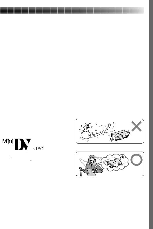
Lithium-ion battery packs are small but possess a large power capacity. However, when the battery pack becomes cool in an environment subject to cold temperatures (below 10°C/50°F), the battery pack has a characteristic that its usage time becomes shorter and may cease to function. If this happens, place the battery pack in your pocket or other warm, protected place for a short time, then re-attach it to the camcorder. As long as the battery pack itself is not cold, it should not affect performance.
(If you’re using some kind of heating pad, make sure the battery pack does not come in direct contact with the pad.)
Lithium-ion is vulnerable in colder temperatures.
6

 EN
EN


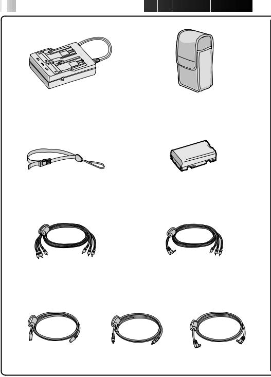
 PROVIDED ACCESSORIES
AC Power |
Soft camera case |
Adapter/Charger AA-V90U |
|
Hand strap |
Battery pack BN-V907U |
VIDEO/AUDIO cable |
VIDEO/AUDIO cable |
(Docking Station to TV or VCR, |
(camcorder to TV or VCR, |
RCA plug 4RCA plug) |
ø 3.5 mini-plug 4RCA plug) |
S-VIDEO cable |
Editing cable |
DC cord |
|
(ø3.5 mini-plug, 2 poles) |
|

EN 7
|
JLIP Video Capture Docking |
|
Station GV-DS2 (referred to in |
T W |
the manual as “Docking Station”) |
|
Use of the JLIP Video Capture Docking Station enables you to capture video images from video sources such as camcorders and VCRs. Also refer to the JLIP Video Capture Docking Station's
instruction manual.
Remote control unit RM-V711U
MiniDV Cassette Tape 30 min |
Power Pack |
CD-ROM |
(DVM-30) M-DV30ME |
CU-V900U |
The CD ROM contains |
|
|
the following |
|
|
2 software programs: |
|
|
• JLIP Video Capture |
|
|
• JLIP Video Producer |
Lithium battery CR2025 |
Cleaning cloth |
(for remote control unit) |
|
Grip strap |
JLIP connection cables x 2 |
PC connection cable, |
|
(ø 3.5 mini-plug, 4 poles) |
D-SUB 9-pin |

8

 EN
EN


 ABOUT
ABOUT DV
DV
The digital video camera converts incoming audio and video signals into digital form for recording.
A video signal is composed of a luminance signal (Y) and color signals (R-Y and B-Y). These signals are identified and recorded digitally (Digital Component Recording). The A/D (Analog to Digital) converter samples the Y signal at 13.5 MHz, and R-Y and B-Y at 3.375 MHz, and changes them to an 8-bit quantum signal.
Sound sampled at 48 kHz is changed to a 16-bit quantum signal, and sound sampled at 32 kHz is converted to a 12-bit signal.
NOTE:
The data recorded on a tape is digital, but the output of this camcorder is analog.
VIDEO |
|
|
|
|
|
|
|
|
|
|
|
|
|
|
|
|
|
|
|
|
Luminance Signal (Y) |
|
|
|
|
|
|
|
|
|
|
|
|
|
|||
Lens |
|
|
A/D |
|
|
|
|
|
|
|
|
|
|
|
||||
|
|
|
|
|
|
|
|
|
|
|
|
|
|
|
|
|
||
|
|
|
|
|
|
conversion |
|
|
|
|
|
Recording by |
||||||
|
|
|
|
|
|
|
|
|
|
|
|
|||||||
|
|
|
Color Difference |
|
|
|
|
|
|
|
rotating head |
|||||||
|
|
|
Signal (R-Y) |
|
|
|
|
|
|
|
helical scan |
|||||||
|
|
|
|
|
|
|
A/D |
|
|
|
|
|
|
|
|
|
|
|
Chrominance (C) |
|
|
Chromatic |
|
|
conversion |
|
|
Signal |
|
|
|
|
|
|
|||
|
|
|
|
Analysis |
|
|
|
|
|
compression |
|
|
|
|
|
|
|
|
|
|
|
A/D |
|
||||||||||||||
|
|
|
|
|
|
|
|
|
|
|
|
|
|
|
|
|
|
|
|
|
|
|
|
|
|
conversion |
|
|
|
|
|
|
|
|
|
|
|
AUDIO |
|
Color Difference |
|
|
|
|
|
|
|
|
|
|
|
|
||||
|
|
|
|
|
|
|
|
|
|
|
|
|
|
|||||
|
Signal (B-Y) |
|
|
|
|
|
|
|
|
|
|
|
|
|
||||
Mic |
|
|
|
|
|
|
A/D |
|
|
|
|
|
|
|
|
|
|
|
|
|
|
|
|
|
conversion |
|
|
|
|
|
|
|
|
|
|
|
|
|
|
|
|
|
|
|
|
|
|
|
|
|
|
|
|
|
|
|
This camcorder separates the data into blocks, writing one block of each data type on each track of the tape.
Tape direction
Sub-Code Area
Video Area
Audio Area
ITI Area
Head tracking direction
5.24 mm / 1/5" |
6.35 mm / 1/4" |
|
|
10 tracks/frame
1 Sub-Code Area
The Time Code and Date/Time data are written here, separate from the video data. This enables you to display the date and time during playback, even if they weren’t displayed while recording.
2 Video Area
3 Audio Area
The digital audio signal is recorded here.
4 ITI (Insert and Tracking
Information) Area
Insert editing and post-recording editing tracking signals are recorded here.
The digital video signal is recorded here.

CONTENTS |
EN 9 |
PROVIDED ACCESSORIES |
6 |
ABOUT DV |
8 |
GETTING STARTED |
10 |
Charging The Battery Pack .................................................................. |
10 |
Installing The Battery Pack ................................................................. |
11 |
Indoor Use ..................................................................................... |
12 |
Using The Power Pack ....................................................................... |
12 |
Date/Time Settings .......................................................................... |
13 |
Loading/Unloading A Cassette ............................................................. |
14 |
Recording Mode Setting ..................................................................... |
15 |
Hand Strap Attachment ...................................................................... |
16 |
Using The Soft Camera Case ................................................................ |
16 |
Grip Strap Attachment ....................................................................... |
17 |
Tripod Mounting .............................................................................. |
17 |
Diopter Adjustment .......................................................................... |
18 |
Remote Control Unit ......................................................................... |
19 |
Operation Mode .............................................................................. |
20 |
RECORDING |
21 |
Basic Recording ............................................................................... |
21 |
Advanced Features ........................................................................... |
27 |
PLAYBACK |
51 |
Basic Playback ................................................................................ |
51 |
Advanced Features ........................................................................... |
52 |
Playback Menu................................................................................ |
54 |
Basic Connections ............................................................................. |
56 |
EDITING |
60 |
Dubbing ........................................................................................ |
60 |
Brand Setting ................................................................................. |
61 |
Random Assemble Editing ................................................................... |
62 |
For More Accurate Editing ................................................................... |
65 |
Audio Dubbing ................................................................................ |
67 |
Insert Editing .................................................................................. |
68 |
TROUBLESHOOTING |
69 |
AFTER USE |
74 |
CONTROLS, INDICATIONS AND CONNECTORS |
75 |
Camcorder ..................................................................................... |
75 |
Docking Station ............................................................................... |
77 |
LCD Monitor/Viewfinder Indications During Recording ................................. |
78 |
LCD Monitor Indications During Playback ................................................. |
79 |
Warning Indications .......................................................................... |
80 |
CAUTIONS |
81 |
SPECIFICATIONS |
83 |
GLOSSARY OF TERMS |
84 |
INDEX |
85 |
10

 EN
EN 


 GETTING
 STARTED
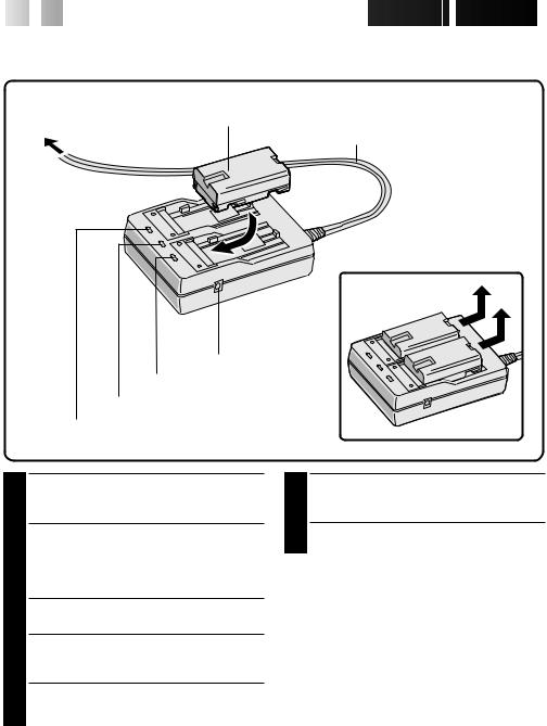
Charging The Battery Pack
You can charge one battery pack at a time, or two consecutively.
ATTACH
Battery pack BN-V907U
To AC outlet
Power cord
DETACH
AC Power
Adapter/Charger
DC jack
Charger indicator 2
Power lamp
Charger indicator 1
1 SUPPLY POWER TO CHARGER
Plug the AC Adapter/Charger’s power cord in to an AC outlet. The power lamp comes on.
2 ATTACH BATTERY/BATTERIES
Remove the battery pack’s protective cap and attach while making sure the 
 marks are facing down and aligned with the corresponding marks on the AC Power Adapter/Charger.
•The Charger Indicator (1 or 2) begins blinking to indicate charging has started.
3 CONFIRM STATUS
When the charger indicator stops blinking but stays lit, charging is finished.
•If two batteries are attached to the charger, they will be charged in the order that they were attached.
4 DETACH BATTERY/BATTERIES
Slide the battery or batteries in the direction of the arrow and lift off.
•Remember to unplug the AC Adapter/ Charger’s power cord from an AC outlet.
CHARGING TIME**
BATTERY |
ONE |
TWO |
BN-V907U |
approx. 100 min. |
approx. 200 min. |
|
|
|


 EN 11
EN 11
NOTES:
cIf you connect the camcorder’s DC cord to the adapter during battery charging, power is supplied to the camcorder and charging stops.
cWhen using the AC Power Adapter/Charger, be sure to use the supplied power cord only.
cThe AC Power Adapter/Charger is for use with the BN-V907U Battery Pack only.
cWhen charging the Battery Pack for the first time or after a long storage period, the Charger Indicator may not light. In this case, remove the Battery Pack from the AC Power Adapter/Charger, then try charging again.
cSince the AC Power Adapter/Charger processes electricity internally, it becomes warm during use. Be sure to use it only in well-ventilated areas.
cIf the battery operation time remains extremely short even after having been fully charged, the battery is worn out and needs to be replaced. Please purchase a new one.
** Charging Environment
Perform charging where the temperature is between 10° and 35°C. (20°–25°C is the ideal temperature range for charging.) If the environment is too cold, charging may be incomplete.
Continuous Shooting
Continuous shooting is possible (See table below for recording time) under the following conditions:
• A BN-V907U Battery Pack is in use
•The temperature is approximately 20°C/68°F However, . . .
•If the temperature is below 10°C/50°F, or
•If zoom or Record-Standby are engaged or LCD monitor is used repeatedly, continuous shooting capability is reduced significantly. Before extended use, it is recommended that you prepare enough battery packs to cover 3 times the planned shooting time.
Installing The Battery Pack
The battery pack does not charge while in the camcorder. Before installation, make sure the battery pack has been charged fully.
1 |
2 |
1 |
|
2 |
Battery cover |
1 OPEN BATTERY COVER
1 Slide the battery cover.
2 Pull open the battery cover in the direction of the arrow.
INSERT BATTERY |
|
2 Insert the |
mark end of the battery first. |
3 CLOSE BATTERY COVER
Close the battery cover while pulling it and slide it in the direction of the arrow.
3 


 mark
mark
Battery
RECORDING TIME
BATTERY |
LCD monitor off/ |
LCD monitor on/ |
|
Viewfinder on |
Viewfinder off |
|
|
|
BN-V907U |
approx. 45 min. |
approx. 40 min. |
|
|
|
NOTES:
cTo remove the battery pack, turn off the camcorder, open the battery cover and slide the battery pack out.
cBe careful not to drop the battery pack.

12EN |
GETTING STARTED (Cont.) |
Indoor Use |
Using The Power Pack |
When using the camcorder indoors, you can use the AC Adapter instead of a battery.
For extended use, prepare the Power Pack, which can be loaded with two battery packs.
To AC outlet
Power lamp When power is
supplied, the power lamp lights.
DC cord
Core Filter 
Power cord
AC Power
Adapter/Charger
DC-IN
Connector is under this cover
1 SUPPLY POWER TO ADAPTER
Plug the AC Adapter/Charger’s power cord in to an AC outlet.
2 SUPPLY POWER TO CAMCORDER
Connect the AC Adapter to the camcorder.
NOTE:
When using the provided DC cord, make sure you connect the end of the cable with the core filter to the camcorder. The core filter improves performance of equipment.

 mark
mark
Knob
Battery cover
DC input jack
DC cord
Screw
INSERT BATTERY |
|
1 Open the battery cover while pressing the |
|
knob and insert the |
end of the battery |
first. Close the battery cover.
2 ATTACH TO CAMCORDER
Attach the camcorder to the Power Pack in the direction of the arrow. Turn the spring-loaded screw inward and turn it clockwise to attach.
3 SUPPLY POWER
Connect the Power Pack DC cord to the camcorder DC input jack.
NOTES:
cWhen the battery remaining power indicator
appears as  , that means the battery power is close to nil. When the battery power is exhausted, power turns off automatically.
cWhen using the Power Pack, the battery pack installed in the camcorder does not supply power.
cAfter the battery packs in the Power Pack are exhausted, the battery pack in the camcorder does not begin to supply power. Detach the Power Pack and turn off the camcorder to use the battery pack installed in the camcorder.


 EN 13
EN 13
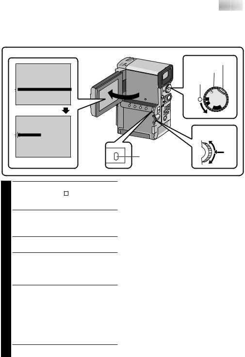
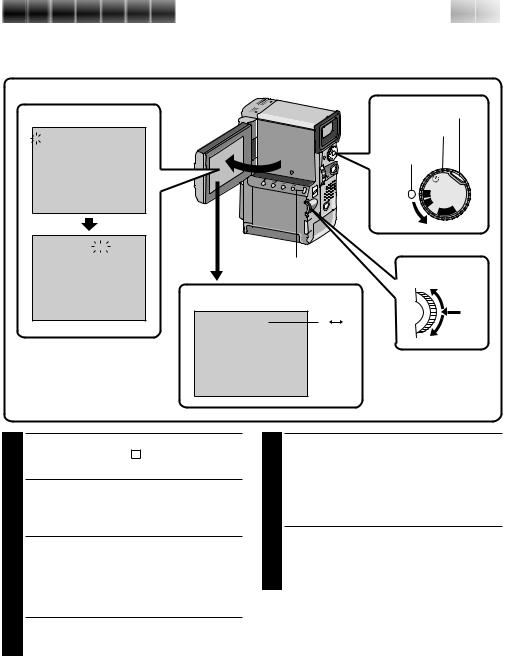
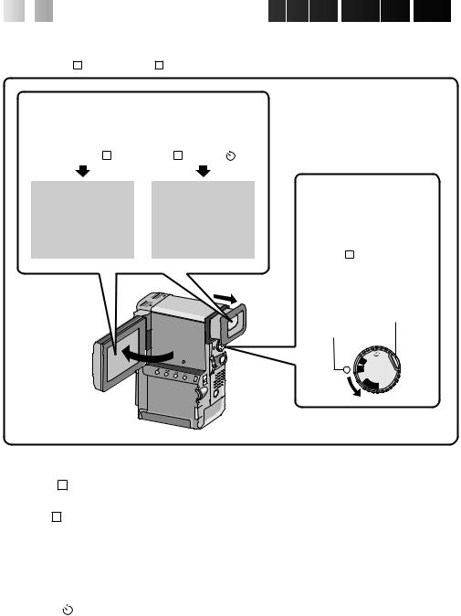
Date/Time Settings
Date and time will automatically be recorded on tape at all times. It is your choice to display it or not during playback (Z pg. 54).
To set date and time follow the instructions from 1 to 4.
LCD monitor
REC MODE |
SP |
WIDE MODE |
OFF |
ZOOM |
20X |
DIS |
OFF |
GAIN UP |
AGC |
FLASH |
AUTO |
4TO DATE / TIME MENU |
|
TO SYSTEM MENU |
|
END |
|
Recording Menu |
|
ON SCREEN |
OFF |
DISPLAY |
ON |
4DATE / TIME |
DEC 25 ’ 97 |
|
PM 5 : 30 |
|
MENU |
RETURN |
MENU button |
|
|
Date/Time Menu |
|
Lock button Power Dial
Power lamp
5S |
|
|
M |
OFFYA |
|
A |
P |
|
|
|
|
|
L |
|
Select Dial
1 SELECT OPERATION MODE
Set the Power Dial to “ M ” while pressing down the lock button located on the dial, and open the LCD monitor fully.
•The power lamp comes on and the camcorder is turned on.
•The LCD monitor can be tilted upward up to 180 degrees and downward up to 90 degrees.
2 ACCESS RECORDING MENU
Press MENU. The Recording Menu appears.
3 ACCESS DATE/TIME MENU
Move the pointer and highlight bar to “TO DATE/TIME MENU” by rotating the Select Dial. Press the Select Dial and the Date/Time Menu appears.
4 INPUT DATE AND TIME
Move the pointer and highlight bar to “DATE/ TIME” by rotating the Select Dial. Press the Select Dial and “month” is highlighted and begins blinking.
Rotating the Select Dial (rotate it upward to increase and downward to decrease), input the month. Press the Select Dial. Repeat the procedure to input the day, year, hour and minute.
•Press the Select Dial twice when the pointer and highlight bar are set to “RETURN” to exit.
Regarding Built-in Rechargeable Battery
To store the date/time in memory, a rechargeable clock lithium battery is integrated in the camcorder. While the camcorder is connected to an AC outlet using the AC Power Adapter/Charger, or while the battery pack installed in the camcorder continues to supply power to the camcorder, the clock lithium battery is always charged. However, if the camcorder is not used for approx. 3 months, the clock lithium battery will become discharged and the date/time stored in memory will be lost. When this occurs, first connect the camcorder to an AC outlet using the AC Power Adapter/Charger etc. for over 24 hours to charge the clock lithium battery. Then perform the date/time setting before using the camcorder.
It is also possible to use the camcorder without the date/time setting.
NOTE:
If you don’t exit the Date/Time Menu, the clock display will not move but the camcorder’s internal clock continues to operate. Once you close the menu, the date and time begin operation from the current date and time, with no delay or loss.

14

 EN
EN 


 GETTING
 STARTED
 (Cont.)
Loading/Unloading A Cassette
The camcorder needs to be powered up to load or eject a cassette.
OPEN/EJECT switch
|
Cassette holder |
|
PUSH HERE |
Make sure the window |
|
side is facing out. |
Cassette cover |
Erase protection switch**
1 OPEN CASSETTE COVER
Turn on the power, then slide the OPEN/EJECT switch in the direction of the arrow. The cassette cover releases. Open the cover in the direction of the arrow until it locks. The holder opens automatically.
• Do not touch internal components.
2 INSERT/REMOVE TAPE
Insert or remove a tape and press “PUSH HERE” to close the cassette holder.
•Once the cassette holder is closed, it recedes automatically. Wait until it recedes completely before closing the cassette cover.
•When the battery’s charge is low, you may not be able to close the cover. Do not apply force. Replace the battery with a fully charged one before continuing.
RECORDING TIME
TAPE |
RECORDING MODE |
|
|
SP |
LP |
DVM-30 |
Approx. 30 min. |
Approx. 45 min. |
DVM-60 |
Approx. 60 min. |
Approx. 90 min. |
|
|
|
NOTES:
cIt takes a few seconds for the cassette holder to open. Do not apply force.
cIf you wait a few seconds and the cassette holder does not open, close the cassette cover and try again.
cBe careful not to get your fingers caught in the holder when it’s closing. If this happens, the holder will open automatically after a few seconds.
cWhen the camcorder is suddenly moved from a cold place to a warm environment, wait a short time before opening the cover.
cClosing the cassette cover before the cassette holder comes out may cause damage to the camcorder.
cWhen shooting again after already shooting a scene, a blank portion is recorded on the tape or a previously recorded scene is erased (recorded over) if you open the cassette cover, regardless of whether the cassette holder comes out or not. See page 22 for information about recording from the middle of a tape.
** To protect valuable recordings . . .
..... slide the erase protection switch on the back of the tape in the direction of “SAVE”. This prevents this tape from being recorded over. If you decide later that you do want to record on this tape, slide the switch back to “REC” before loading the tape.
Recording Mode Setting
Set depending on your preference.
LCD monitor
Recording Menu
4 |
REC MODE |
|
SP |
|
WIDE MODE |
|
OFF |
|
ZOOM |
20X |
|
|
DIS |
OFF |
|
|
GAIN UP |
AGC |
|
|
FLASH |
AUTO |
|
TO DATE / TIME MENU
TO SYSTEM MENU
END
4REC MODE |
SP |
|
WIDE MODE |
OFF |
|
ZOOM |
20X |
|
DIS |
OFF |
|
GAIN UP |
AGC |
|
FLASH |
AUTO |
|
TO DATE / TIME MENU
TO SYSTEM MENU
END


 EN 15
EN 15
Lock button
Power dial
Power lamp
5S |
|
|
M |
OFFYA |
|
A |
P |
|
|
|
|
|
L |
|
MENU button
Select Dial
Recording mode indicator
SP |
SP |
LP |
1 SELECT OPERATION MODE
Set the Power Dial to “ M ” while pressing down the lock button located on the dial.
2 OPEN LCD MONITOR
Open the LCD monitor fully.
The power lamp comes on and the camcorder is turned on.
•The LCD monitor turns on/off automatically when it is opened/closed at approx. 90 degrees while the Power Dial is set to any operation mode (except “OFF”).
•The LCD monitor can be tilted upward up to 180 degrees and downward up to 90 degrees.
3 ACCESS RECORDING MENU
Press MENU. The Recording Menu appears.
4 SET RECORDING MODE
First move the pointer and highlight bar to “REC MODE” by rotating the Select Dial. Press the Select Dial and the parameter “SP” or “LP” is highlighted. Select “SP” or “LP” by rotating the Select Dial. Press the Select Dial to exit from the Recording Menu.
•Insert Editing or Audio Dubbing is impossible on a tape recorded in the LP mode.
•“LP” (Long Play) is more economical, recording at 2/3 the speed of “SP” (Standard Play).
NOTES:
cIf the recording mode is switched during recording, the playback picture will be blurred at the switching point.
cIt is recommended that tapes recorded in the LP mode on this camcorder be played back on this camcorder.
cDuring playback of a tape recorded on another camcorder, blocks of noise may appear or there may be momentary pauses in the sound.
16EN |
GETTING STARTED (Cont.) |
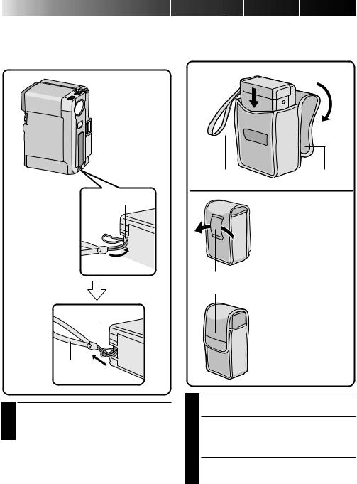
Hand Strap Attachment |
Using The Soft Camera Case |
The provided Hand Strap helps you to keep a firm hold on the camcorder. Make sure you never hold the camcorder without using the Hand Strap.
Keep the camcorder in the soft camera case when transporting it.
 2
2
 3
3
1
Flap
Eyelet
During transporting ...
Thread your belt through the soft camera case's loop for nohands carrying.
1
Hand strap
Loop
2
When putting the camcorder with the Power Pack attached into the soft camera case ...
Close the flap loosely, attaching it to the velcro on the soft camera case.
1 ATTACH HAND STRAP
Thread the strap through the eyelet 1, then thread the loop through the end of the strap 2. Pull firmly to ensure secure attachment.
1
2 PUT CAMCORDER IN
Insert with lens side down. By doing this, you can begin shooting as soon as you take out the camcorder from the soft camera case.
3 CLOSE FLAP


 EN 17
EN 17
Grip Strap Attachment
Before attaching the grip strap, detach the hand strap from the camcorder (Z pg. 16).
Hand strap eyelet
Loop
1 ATTACH GRIP STRAP TO HAND STRAP EYELET
Thread the end of the grip strap through the hand strap eyelet, then thread the other end of the grip through the loop. Pull firmly to ensure secure attachment.
2 ATTACH GRIP STRAP TO SUB HAND STRAP EYELET
Open the pad and thread the end of the grip strap through the sub hand strap eyelet.
3 ADJUST LENGTH
Adjust so your thumb and fingers can easily operate the START/STOP button and the zoom switch 1. Position the pad so that it contacts the back of your hand 2, then re-attach it 3.
NOTE:
If you want to take a snapshot (Z pg. 27) while grasping the camcorder through the Grip strap attached to the hand strap eyelet and the sub hand strap eyelet, press the Sub SNAPSHOT button (3) using your left hand. Because the SNAPSHOT button will be covered by your right hand, pressing it will not be possible.
Zoom switch
START/STOP
Pad
 3
3
Pad |
1 2 |
Sub hand strap eyelet
Tripod Mounting
Align the tripod’s screw with the mounting socket on the bottom of the camcorder.
The camcorder can be mounted on a tripod even with the Power Pack attached.
Bottom of the camcorder
18

 EN
EN 


 GETTING
 STARTED
 (Cont.)
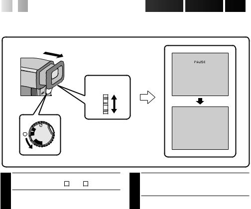
Diopter Adjustment
Adjust the viewfinder display for best viewing.
Diopter
adjust lever Diopter adjust lever
 PAUSE
PAUSE 
5S  M
M  A
A
 OFF
OFF
 YALP
YALP
1
2
SELECT OPERATION MODE
Set the Power Dial to “ A ”, or “ M ”.
TURN ON CAMCORDER
Pull out the viewfinder fully.
3 ADJUST DIOPTER
Slide the Diopter Adjust Lever located on the bottom of the viewfinder.
•Slide in either direction, while looking at the viewfinder display, until it looks best to you.


 EN 19
EN 19
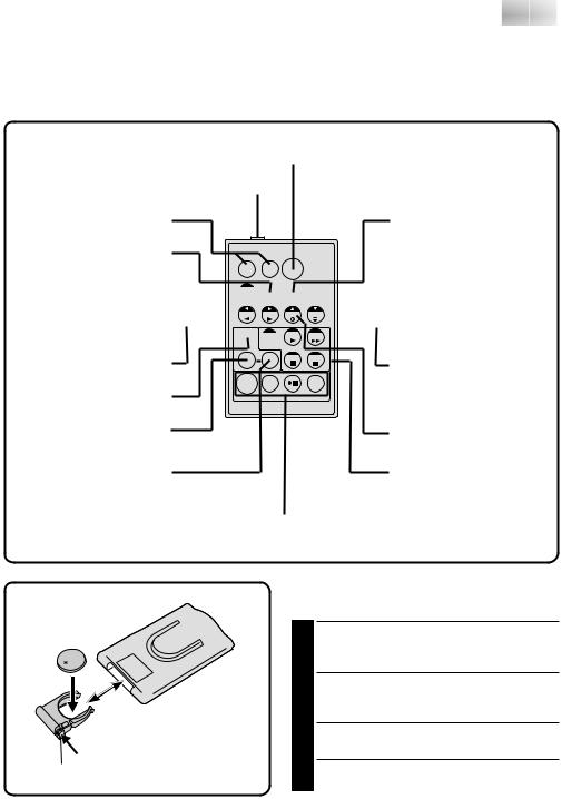
Remote Control Unit
You can use the RM-V711U to control the camcorder. When using the remote control, be sure to point it at the remote sensor. The transmitted beam effective area for indoor use is approx. 5 m. The transmitted beam may not be effective or may cause incorrect operation if the remote sensor is directly exposed to sunlight or powerful lighting.
START/STOP Button (Z pg. 68)
PAUSE IN connector (Z pg. 62) |
|
Zoom Buttons (Z pg. 52) |
AUDIO MONITOR Button |
|
(Z pg. 67) |
DISPLAY Button (Z pg. 67) |
|
T |
W |
SHIFT Button (Z pg. 52) 

SLOW Rewind/Forward  Buttons (Z pg. 51)


 MBR SET Button (Z pg. 61)
 A. DUB Button (Z pg. 67)
Left/Right Buttons (Z pg. 52)
FADE/WIPE Button (Z pg. 63)
EFFECT Button (Z pg. 53)
EFFECT ON/OFF Button (Z pg. 53)
Down Button (Z pg. 52)
 INSERT Button (Z pg. 68)
Up Button (Z pg. 52)
Operation Buttons (Z pg. 52, 68)
R.A. EDIT Buttons (Z pg. 63)
Installing The Battery
The RM-V711U uses one lithium battery (CR2025).
|
PULL OUT BATTERY HOLDER |
|
1 Pull out in the direction of the arrow while |
|
pressing the knob as shown. |
|
INSERT BATTERY IN HOLDER |
|
2 Insert the battery in the holder, and be sure to |
|
have the “+” mark visible. |
|
RE-INSERT HOLDER |
|
3 Slide the holder back in until you hear a click. |
Knob |
•Read the caution concerning lithium batteries |
|
(Z pg. 2). |
20

 EN
EN 


 GETTING
 STARTED
 (Cont.)
Operation Mode
Tuning the Power Dial allows you to choose the appropriate operation mode among the following modes: Full Auto mode ( A ), Manual mode ( M ), 5 second mode recording (5S), Self-Timer mode ( ) and “PLAY”.
According to the Power Dial position you have selected, “F.AUTO” or “MANUAL” appears in the upper left corner.
When set to “ A ” |
|
|
When set to |
|||||||
|
“ M ”, “5S” or “ ” |
|||||||||
|
|
|
|
|
|
|
|
|
|
|
F . AUTO |
|
MANUAL |
||||||||
|
|
PAUSE |
|
|
|
|
|
PAUSE |
|
|
|
|
|
|
|||||||
|
|
|
|
|
||||||
|
|
|
|
|
|
|
|
|
|
|
To turn on the camcorder, first turn the Power Dial to any operation mode except “OFF”, then pull out the viewfinder fully or open the LCD monitor. When turning the Power Dial from “OFF” to “ A ” or when turning it from “OFF” to “PLAY”, press and hold the lock button located on the dial.
Lock button
Power lamp
5S  M
M  A
A
 OFF
OFF
 YALP
YALP
Power Dial Position |
Function |
|
|
Full Auto: A |
Allows you to record using NO special effects or manual adjust- |
|
ments. Suitable for standard recording. |
|
|
Manual: M |
Allows you to set various recording functions using the Menus. If |
|
you want more creative capabilities than Full Auto recording, try |
|
this mode. |
|
|
5 second mode recording: 5S |
Allows you to record in 5-second clips to keep the action moving. |
|
Other menu settings are the same as Full Auto mode, however |
|
manually adjusted White Balance Adjustment settings are |
|
effective. |
|
|
Self-Timer: |
Allows you (camcorder operator) to become part of the scene |
|
once the camcorder is set. This mode is similar to the Self-Timer |
|
on film cameras. |
|
|
Playback: PLAY |
Allows you to play back a recording, Z pg. 51 – 59. |
|
|
RECORDING 


 EN 21
EN 21
Basic Recording
You should already have performed the necessary preparations (Z pgs. 10 – 18). Set the Power Dial to “ A ” and try recording that way before attempting to use more advanced features.
NOTE:
Before starting recording, make sure you set the date and time (Z pg. 13). Even if they don’t appear during recording, you can display them during playback (Z pg. 55).
Power lamp |
|
M |
Lock button |
5S |
|
A |
Power Dial |
OFF |
|
Y |
|
ALP |
|
START/STOP button
Display
 PAUSE
PAUSE 
Record-Standby
Display
REC
444
IND. ON/OFF
1 SELECT OPERATION MODE
Set the Power Dial to “ A ” while pressing down the lock button located on the dial.
2 PULL OUT VIEWFINDER OR OPEN LCD MONITOR
Pull out the viewfinder fully or open the LCD monitor to approx. 90° degrees.
•The lens cover opens, the power lamp comes on and the scene you're aimed at appears.
•The Record-Standby mode is engaged.
3 START RECORDING
When “PAUSE” appears, press START/STOP. A beep signals the start of recording.
4 STOP RECORDING
Press START/STOP again to stop recording.
•The camcorder re-enters Record-Standby mode.
5 END RECORDING
When you’re finished recording, push back the viewfinder or close the LCD monitor until it clicks; the lens cover closes and the power lamp goes out.
•When transporting, make sure the viewfinder is pushed back and the LCD monitor is closed and locked.
•To turn power on again, pull out the viewfinder or open the LCD monitor.
OR
Set the Power Dial to “OFF”.
•When turning to “OFF”, it is not necessary to press down the lock button.
During recording
NOTES:
cThe image will not appear simultaneously in the LCD monitor and the viewfinder. No image appears on the LCD monitor when the viewfinder is pulled out. It is not possible to shoot using both LCD monitor and viewfinder.
cIf 5 minutes elapse in the Record-Standby mode, power shuts off automatically to conserve energy and protect the heads. To turn the camcorder on again, push back and pull out the viewfinder again or close and re-open the LCD monitor. As long as you don’t take out the tape you were using or play it back, you can continue from where you left off with no noticeable brake on the recorded video.
cWhen a blank portion is left between recorded scenes on the tape, the time code is interrupted and errors may occur when editing the tape.
Continue recording from where you stop so there
are no gaps by following "Recording from the middle of a tape" (Z pg. 22).
cRecored-Standby means that a tape is loaded and the camcorder is ready to record.
cDuring recording, sound is not heard from the speaker. If you want to hear the sound, connect optional headphones to the headphones jack. The sound volume at this point is the same as the level it was adjusted during playback.
cTo make the indications disappear, press and hold the IND.ON/OFF button for more than approx. 1 second. However, it is impossible to remove the
tape running indicator “444” and warning indications and so on (Z pg. 78).
cUse the viewfinder when under direct sunlight or when reflections make it difficult to see the LCD monitor.

22

 EN
EN 


 RECORDING
 (Cont.)
Recording From The Middle Of A Tape
When removing a tape on which you were recording, or when you resume recording on a tape after playing back the recording previously made (without taking the tape out between recordings), perform this procedure.
A |
M |
 OFFY
OFFY
A
L
P
5S  M
M  A
A
 OFF
OFF  YALP
YALP
5S 

 Lock button
 Power Dial
MENU |
START/STOP Button |
|
STOP |
REW FF |
PLAY/PAUSE
1 SELECT OPERATION MODE
Turn the Power Dial to “PLAY” while pressing down the lock button located on the dial.
2 PULL OUT VIEWFINDER OR OPEN LCD MONITOR
Pull out the viewfinder fully or open the LCD monitor to approx. 90° degrees.
•The lens cover opens, the power lamp comes on.
3 START SEARCH
Press 4/6, then press 2or 3. Watch in the viewfinder or the LCD monitor for the spot where you want to begin recording.
4 ENGAGE STILL MODE
Once you find the spot at which you want to start recording, press 4/6to engage the Still mode.
5 START RECORDING
Turn the Power Dial to any operation mode except “PLAY” and “OFF”, then press START/ STOP.
•Start recording from a point prior to the end of the last recording. A few seconds of the end of the last recording will be erased.
NOTE:
If you start recording from the end of the previous recording leaving no blank space, there may be situations where a clean transition is not possible.


 EN 23
EN 23
Time Code
During recording, a time code is recorded on the tape. This code is to confirm the location of the recorded scene on the tape during playback.
If recording starts from a blank portion, the time code begins counting from “00:00:00” (minute:second:frame). If recording starts from the end of a previously recorded scene, the time code continues from the last time code number.
To perform Random Assemble Editing (Z pg. 62), time code is necessary. If during recording a blank portion is recorded partway through the tape, the time code is interrupted. When recording is resumed, the time code starts counting up again from “00:00:00”. This means the camcorder may record the same time codes as those existing in a previously recorded scene. To prevent leaving a blank portion on a tape, perform the procedure in “Recording From The Middle of A Tape” (Z pg. 22) in the following cases;
•After playing back the recorded tape, when you shoot again.
•When power shuts off during shooting. •When a tape is removed and re-inserted
during shooting.
•When shooting using a partially recorded tape. •When shooting on a blank portion located
partway through the tape.
•When shooting again after already shooting a scene and opening/closing the cassette cover.
Display
|
|
|
|
Time code is displayed |
||
|
|
|
|
during playback. |
||
|
|
|
|
|
|
Minutes |
|
|
|
|
|
||
|
|
|
|
|
|
Seconds |
|
|
|
|
|
|
|
|
|
|
|
|
|
Frames |
TC 12 : 34 : 29 |
|
|
|
|||
|
|
|
||||
|
|
|
|
|
|
(30 frames = 1 second) |
NOTES:
cThe Time Code cannot be reset.
cDuring fast-forwarding and rewinding, time code indication does not move smoothly.
When blank portion is recorded on a tape
Time code |
|
|
Time code |
Time code |
|
|||
00:00:00 |
|
|
05:43:21 |
00:00:00 |
|
|||
|
|
|
|
|
|
|
|
|
Tape |
|
Already recorded scene |
|
Blank |
|
|
Newly recorded scene |
|
|
|
|
|
|
|
|||
Shooting start point |
Shooting stop point |
Shooting start point |
||||||
Proper recording |
|
|
|
|
|
|
||
Time code |
|
|
Time code |
Time code |
|
|||
00:00:00 |
|
|
05:43:21 |
05:44:00 |
|
|||
|
|
|
|
|
||||
Tape |
|
Already recorded scene |
|
New scene |
|
Latest scene |
||
|
|
|
|
|
|
|
|
|
Shooting start point |
Shooting start point |
Shooting start point |

24

 EN
EN 


 RECORDING
 (Cont.)
Tape Remaining Indicator
The time remaining on the tape is automatically monitored and displayed (Z pg. 78). When the tape ends, “TAPE END” appears. If the indications are turned off, the tape remaining indicator appears when remaining time reaches 2 minutes.
Display
90 min |
89 min |
3 min |
2 min |
REC |
|
|
|
|
|
|
blinking |
|
|
0 min |
1 min |
|
|
blinking |
blinking |
BRIGHT |
– – – – –6– – – – – |
Select Dial
MENU
IND.ON/OFF button
Brightness Control
You can adjust the brightness of the LCD monitor by rotating the Select Dial.
1 ADJUST BRIGHTNESS
If you want to brighten the image...
Rotate the Select Dial upward until the brightness indicator moves and the LCD monitor reaches its appropriate brightness.
If you want to darken the image...
Rotate the Select Dial downward until the brightness indicator moves and the LCD monitor reaches its appropriate brightness.
•The brightness indication appears in the LCD monitor.
LCD Monitor/Viewfinder Indications
You can make the LCD monitor/Viewfinder indications appear/disappear.
1 PRESS IND.ON/OFF BUTTON
When you do not want the indications to appear, press the IND.ON/OFF button for longer than approximately 1 second. Certain indications disappear.
Press again for longer than approx. 1 second to make the indicaitons reappear.
NOTE:
It is impossible to make the tape running indicator and warnings etc. disappear from the LCD monitor or the viewfinder. For the indications that can be removed, Z pg. 78


 EN 25
EN 25
Journalistic shooting
In some situations different angles of shooting may be required for more dramatic results.
1
2
OPEN LCD MONITOR
Make sure the viewfinder is pushed back and the LCD monitor is fully open (approx. 90°).
TILT LCD MONITOR
Tilt the LCD monitor in the most convenient direction.
•The LCD monitor can rotate almost full circle (270°: 90° downward, 180° upward).
Interface Shooting
You can shoot yourself while viewing your own image in the LCD monitor.
1
2
TILT LCD MONITOR UPWARD
Open the LCD monitor and tilt it upward to 180 degrees so that it faces forward.
START RECORDING
Point the lens towards yourself and start recording.
•During Interface Shooting, the “Tape Running” indicator and warning indications
(Z pg. 80) are the only ones that will be shown; they will appear horizontally reversed in the display, but are not reversed in the recording.
NOTE:
The tape remaining indicator does not appear during interface shooting. However, when the remaining time reaches 2 minutes, the indicator appears showing the remaining time: –

 – –
– –
(blinking) – – |
(blinking) – |
(blinking) |
26

 EN
EN 


 RECORDING
 (Cont.)
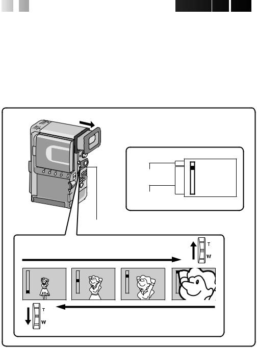
Zoom
Select any one of the three powers of magnification and get “closer” to the subject (Z pg. 34).
Simply set the zoom switch to either zoom in (towards “T”) or zoom out (towards “W”). The zoom speed is variable — the quicker you set the zoom switch, the quicker the zoom action.
NOTES:
cZoom magnification of over 10X is done through Digital image processing, and is therefore called Digital Zoom.
cDuring Digital Zoom, the quality of image may suffer.
cDigital zoom cannot be used while the Video Echo effect (Z pg. 45), Snapshot Dissolve, the Picture Wipe/Dissolve function (Z pg. 40) or the 5SD mode (Z pg. 30) are activated.
cMacro shooting (as close as approx. 3 cm to the subject) is possible when the zoom switch is set all the way to “W”.
|
D |
Digital |
T |
|
|
zoom zone |
|
10X (optical) |
W |
|
zoom zone
Zoom display
Zoom switch
Zoom in (T: Telephoto)
D |
D |
D |
D |
T |
T |
T |
T |
W |
W |
W |
W |
Zoom out (W: Wide angle)

RECORDING Advanced Features


 EN 27
EN 27
Snapshot
Use your camcorder like a regular camera and take a snapshot, or several of them in succession.
5S  M
M  A
A
 OFF
OFF  YALP
YALP
 Lock button
 Power Dial
|
|
Display |
|
|
PAUSE |
|
PHOTO |
|
Flash |
|
|
Sub SNAPSHOT |
During snapshot |
Flash Ready Indicator |
SNAPSHOT |
|
|
Press SNAPSHOT during recording (Snapshot dissolve)
SNAPSHOT
Press SNAPSHOT during Record-Standby mode
1 SELECT OPERATION MODE
First turn the Power Dial to any operation mode except “PLAY” and “OFF”, make sure the viewfinder is pulled out or the LCD monitor is open fully.
2 TAKE SNAPSHOT
Press SNAPSHOT.
If you press during Record-Standby...
.... “PHOTO” appears and a still image will be recorded for approx. 5 seconds, then the camcorder re-enters the Record-Standby mode.
If you press during Recording...
.... “PHOTO” appears and a still image will be recorded for approx. 5 seconds. The next image then gradually overlaps the snapshot and normal recording resumes.
•The sound effect of a shutter closing is recorded together with the image.
Snapshot Flash:
The flash automatically lights at the subject when it's dark (flash ready indicator  appears in the viewfinder or the LCD monitor) when taking a snapshot in Record-Standby (Z pg. 28)
Motor Drive mode:
Keeping SNAPSHOT pressed provides an effect similar to serial photography. (The interval between the still pictures: approx. 0.7 seconds.)
Changing the Snapshot Setting:
•Still image with no frame can also be recorded (Z pg. 36).
•When you don't want to hear the shutter sound, set BEEP/TALLY to “OFF” in the system menu (Z pg. 36). Though the sound is not heard from the speaker, it is recorded on the tape.
NOTE:
When the grip strap is fastened to both the strap eyelet and the sub-strap eyelet, use the Sub SNAPSHOT button to take a snapshot.
 Loading...